EP0458027A1 - Servosystem für Plattenabspielgerät - Google Patents
Servosystem für Plattenabspielgerät Download PDFInfo
- Publication number
- EP0458027A1 EP0458027A1 EP91104256A EP91104256A EP0458027A1 EP 0458027 A1 EP0458027 A1 EP 0458027A1 EP 91104256 A EP91104256 A EP 91104256A EP 91104256 A EP91104256 A EP 91104256A EP 0458027 A1 EP0458027 A1 EP 0458027A1
- Authority
- EP
- European Patent Office
- Prior art keywords
- track
- pickup
- servo system
- pickup head
- servo
- Prior art date
- Legal status (The legal status is an assumption and is not a legal conclusion. Google has not performed a legal analysis and makes no representation as to the accuracy of the status listed.)
- Withdrawn
Links
- 238000009877 rendering Methods 0.000 claims abstract description 4
- 230000003287 optical effect Effects 0.000 claims description 8
- 230000005236 sound signal Effects 0.000 description 3
- 230000004048 modification Effects 0.000 description 2
- 238000012986 modification Methods 0.000 description 2
- 239000000725 suspension Substances 0.000 description 2
- 238000010586 diagram Methods 0.000 description 1
- 239000000758 substrate Substances 0.000 description 1
Images

Classifications
-
- G—PHYSICS
- G11—INFORMATION STORAGE
- G11B—INFORMATION STORAGE BASED ON RELATIVE MOVEMENT BETWEEN RECORD CARRIER AND TRANSDUCER
- G11B7/00—Recording or reproducing by optical means, e.g. recording using a thermal beam of optical radiation by modifying optical properties or the physical structure, reproducing using an optical beam at lower power by sensing optical properties; Record carriers therefor
- G11B7/08—Disposition or mounting of heads or light sources relatively to record carriers
- G11B7/09—Disposition or mounting of heads or light sources relatively to record carriers with provision for moving the light beam or focus plane for the purpose of maintaining alignment of the light beam relative to the record carrier during transducing operation, e.g. to compensate for surface irregularities of the latter or for track following
- G11B7/0925—Electromechanical actuators for lens positioning
- G11B7/0933—Details of stationary parts
-
- G—PHYSICS
- G11—INFORMATION STORAGE
- G11B—INFORMATION STORAGE BASED ON RELATIVE MOVEMENT BETWEEN RECORD CARRIER AND TRANSDUCER
- G11B7/00—Recording or reproducing by optical means, e.g. recording using a thermal beam of optical radiation by modifying optical properties or the physical structure, reproducing using an optical beam at lower power by sensing optical properties; Record carriers therefor
- G11B7/08—Disposition or mounting of heads or light sources relatively to record carriers
- G11B7/085—Disposition or mounting of heads or light sources relatively to record carriers with provision for moving the light beam into, or out of, its operative position or across tracks, otherwise than during the transducing operation, e.g. for adjustment or preliminary positioning or track change or selection
- G11B7/08505—Methods for track change, selection or preliminary positioning by moving the head
Definitions
- Information recorded on the disk is read by the pickup head of the pickup and converted into electric signals. Signals representing a focus error of a laser beam and a tracking error are fed to a focus servo and a track-following servo system.
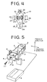
- Fig. 5 shows a conventional optical pickup.
- the optical pickup comprises a pickup head 2, a printed circuit board 4, and a base plate 6.
- the pickup head 2 has an optical system 1 and a pair of coils (not shown).
- the pickup head 2 is suspended from the print circuit board 4 by four conductive wires 3 in the form of a cantilever.
- the base plate 6 is secured to the board 4 by a screw 7 through a plastic connecting member 5.
- the printed circuit board 4 is connected to a head substrate 9 with a flexible wiring plate 8.
- the pickup head is suspended by conductive wires in the form of a cantilever.
- the track-following servo system is inoperative during the track searching operation so that the movement of the pickup head 2 in the radial direction of the disk is not restricted. Accordingly, a vibration due to the radial movement of the pickup, or an external force may cause the pickup head 2 to vibrate, rendering it impossible to accurately count the track.
- the object of the present invention is to provide a track-following servo system where a rapid track search may be performed with a high accuracy.
- a servo system for an optical pickup head of a pickup including a focus servo system for focusing an objective and a track-following servo system for following a track of a disk, comprising disabling means for rendering one of the focus servo system and the track-following system inoperative, restricting means for restricting movement of the pickup head in an operating direction of the disabled system during an inoperative period.
- the disabled system is the track-following servo system
- the restricting means includes stoppers and means for energizing a tracking coil of the track-following servo system, for shifting the pickup head to one of the stoppers whereby a part of the pickup head is abutted on the stopper.
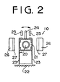
- the optical pickup 10 comprises a pickup head 21 having an objective 20 and a suspension base 22.
- the pickup head 21 is suspended from the suspension base 22 by four conductive wires 23 in the form of a cantilever adjacent the pickup at opposite sides of the pickup head 21.
- a tracking coil 28 (Fig. 1) is provided adjacent the head 21 so as to follow the track in accordance with a tracking error signal.
- a pair of magnets 27 respectively mounted on yokes 26 are provided adjacent to opposite sides of the pickup head 21.
- the pickup 10 reads information recorded on a CD 17 and produces a signal corresponding to the information.
- the pickup further produces a control signal for producing the information signal, a focus error signal and a tracking error signal.
- the output signals of the pickup 10 is applied to a preamplifier 11 provided in the servo system, which amplifies the output signals of the pickup 10.
- the amplified information signal is fed to a decoder 12 wherein the signal is decoded to produce a digital audio signal.
- the digital audio signal is converted into an analog audio signal at a D/A converter 13.
- the servo system has a track-following servo 16 which has a tracking servo switch S1 connected with the preamplifier 11.
- the tracking servo 16 is further provided with a compulsory operation switch S2 which is connected to the tracking coil 28 through a resistor R .
- the switches S1 and S2 are actuated by a controller 14 which is operated by a manipulator 15.
- a spindle motor 18 controlled by a spindle servo 19 is provided in the servo system to rotate the disk 17 at a predetermined speed.
- the pickup head 21 has a projection 24 which is provided between a pair of stoppers 25.
- the tracking servo 16 When the operation for searching the desired track is carried out, the tracking servo 16 is rendered inoperative and the tracking coil 28 is energized. Thus, the pickup head 21 is shifted in one of the directions shown by arrows in Fig. 2. The pickup head 21 is held at a position where the projection 24 abuts against one of the stoppers 25. The coefficient of friction between the projection 24 and the stopper 25 is so small as to allow the pickup head 21 to be shifted in a focusing direction.
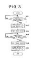
- a track search key in the manipulator 15 it is determined whether a track search key in the manipulator 15 is operated to instruct the search of the desired track.
- the tracking servo switch S1 is opened and the compulsory operation switch S2 is closed in a step 302.
- the tracking operation is stopped and the tracking coil 28 is energized.
- the pickup head 21 is attracted toward one of the magnets 27 accordingly and held at the position where the projection 24 engages the corresponding stopper 25.
- the pickup 10 In order to carry out the search of the desired track, the pickup 10 is moved in the radial direction of the disk 17 by a carriage (not shown) in a step 303. Since the pickup head 21 is prevented from vibrating in the radial direction of the disk 17, any search error caused by skipping a track is prevented so that an accurate search is conducted.
- step 304 the track search operation is terminated at a step 305.
- the program goes to a step 306 so that the tracking servo switch S1 is closed and the compulsory operation switch S2 is opened.
- the coil 28 is de-energized so that the pickup head 21 returns to the normal position. Thereafter, the pickup head 21 reads the information recorded on the recording surface of the disk 17.
- Fig. 4 shows another example of the pickup to which the present invention is applied.
- the same numerals as those in Fig. 2 designate the same parts as Fig. 2 so that the descriptions thereof are omitted.
- the pickup head 21 is rotatably mounted on a rod 21a fixed to a base of the pickup 10.
- a pair of yokes 21c are provided in holes 21b formed in the pickup head 21.
- the pickup head 21 is prevented from shifting in the tracking direction so that any search error, such as a skipping of the track, does not occur.
- the pickup head 21 is held immovable when the tracking servo system 16 is inoperative in the above described embodiment, the system may be modified to hold the pickup 10 during the focusing operation as well. Furthermore, the pickup 10 may be held upon the start of rough servo operation.
- the present invention may be applied to other disk reproducing system, for example, a laser disk (LD), optical or video disk player.
- LD laser disk
- video disk player for example, a laser disk (LD), optical or video disk player.
- the present invention provides a track-following servo system, wherein a skipping track is prevented so that the desired track can be accurately searched. Thus, a rapid track search is performed.
Landscapes
- Moving Of The Head For Recording And Reproducing By Optical Means (AREA)
- Moving Of Head For Track Selection And Changing (AREA)
- Optical Recording Or Reproduction (AREA)
Applications Claiming Priority (2)
| Application Number | Priority Date | Filing Date | Title |
|---|---|---|---|
| JP13152390A JPH0426964A (ja) | 1990-05-21 | 1990-05-21 | サーボ装置 |
| JP131523/90 | 1990-05-21 |
Publications (1)
| Publication Number | Publication Date |
|---|---|
| EP0458027A1 true EP0458027A1 (de) | 1991-11-27 |
Family
ID=15060052
Family Applications (1)
| Application Number | Title | Priority Date | Filing Date |
|---|---|---|---|
| EP91104256A Withdrawn EP0458027A1 (de) | 1990-05-21 | 1991-03-19 | Servosystem für Plattenabspielgerät |
Country Status (2)
| Country | Link |
|---|---|
| EP (1) | EP0458027A1 (de) |
| JP (1) | JPH0426964A (de) |
Cited By (4)
| Publication number | Priority date | Publication date | Assignee | Title |
|---|---|---|---|---|
| EP0546543A3 (en) * | 1991-12-13 | 1993-07-28 | Sony Corporation | Disc driving apparatus |
| EP0617418A1 (de) * | 1993-03-22 | 1994-09-28 | Sony Corporation | Zweiachsige Positioniereinrichtung |
| EP0618570A1 (de) * | 1993-04-02 | 1994-10-05 | Koninklijke Philips Electronics N.V. | Gerät zum Aufzeichnen und/oder zum Wiedergeben von Informationen mittels eines Strahlungsbündels |
| US5524004A (en) * | 1993-04-02 | 1996-06-04 | U.S. Philips Corporation | Suspension for the optical head of a disc scanner with mechanical limiting of objective lens |
Families Citing this family (1)
| Publication number | Priority date | Publication date | Assignee | Title |
|---|---|---|---|---|
| JP3012988U (ja) * | 1994-12-26 | 1995-06-27 | 船井電機株式会社 | 光ディスク再生装置 |
Citations (2)
| Publication number | Priority date | Publication date | Assignee | Title |
|---|---|---|---|---|
| DE3626029A1 (de) * | 1985-08-03 | 1987-02-12 | Olympus Optical Co | Optische aufnahme/wiedergabevorrichtung |
| EP0302666A2 (de) * | 1987-08-04 | 1989-02-08 | Canon Kabushiki Kaisha | Optisches Informationsverarbeitungsgerät, welches mit Mitteln zum Halten in einer vorgesehenen Position eines optischen Systems versehen ist, wenn Abnormalitäten bei der Spurführungs- oder Fokussierungssteuerung auftreten |
-
1990
- 1990-05-21 JP JP13152390A patent/JPH0426964A/ja active Pending
-
1991
- 1991-03-19 EP EP91104256A patent/EP0458027A1/de not_active Withdrawn
Patent Citations (2)
| Publication number | Priority date | Publication date | Assignee | Title |
|---|---|---|---|---|
| DE3626029A1 (de) * | 1985-08-03 | 1987-02-12 | Olympus Optical Co | Optische aufnahme/wiedergabevorrichtung |
| EP0302666A2 (de) * | 1987-08-04 | 1989-02-08 | Canon Kabushiki Kaisha | Optisches Informationsverarbeitungsgerät, welches mit Mitteln zum Halten in einer vorgesehenen Position eines optischen Systems versehen ist, wenn Abnormalitäten bei der Spurführungs- oder Fokussierungssteuerung auftreten |
Non-Patent Citations (2)
| Title |
|---|
| PATENT ABSTRACTS OF JAPAN vol. 12, no. 125 (P-691)(2972) 19 April 1988, & JP-A-62 250525 (KYOCERA CORP) 31 October 1987, * |
| PATENT ABSTRACTS OF JAPAN vol. 9, no. 199 (P-380)(1922) 16 August 1985, & JP-A-60 063739 (CANON K.K.) 12 April 1985, * |
Cited By (6)
| Publication number | Priority date | Publication date | Assignee | Title |
|---|---|---|---|---|
| EP0546543A3 (en) * | 1991-12-13 | 1993-07-28 | Sony Corporation | Disc driving apparatus |
| US5485445A (en) * | 1991-12-13 | 1996-01-16 | Sony Corporation | Disc driving apparatus having means for placing a read record head at a predetermined position in the innermost region of a disc |
| EP0617418A1 (de) * | 1993-03-22 | 1994-09-28 | Sony Corporation | Zweiachsige Positioniereinrichtung |
| US5519677A (en) * | 1993-03-22 | 1996-05-21 | Sony Corporation | Biaxial actuator for driving an objective lens in both focusing and tracking directions |
| EP0618570A1 (de) * | 1993-04-02 | 1994-10-05 | Koninklijke Philips Electronics N.V. | Gerät zum Aufzeichnen und/oder zum Wiedergeben von Informationen mittels eines Strahlungsbündels |
| US5524004A (en) * | 1993-04-02 | 1996-06-04 | U.S. Philips Corporation | Suspension for the optical head of a disc scanner with mechanical limiting of objective lens |
Also Published As
| Publication number | Publication date |
|---|---|
| JPH0426964A (ja) | 1992-01-30 |
Similar Documents
| Publication | Publication Date | Title |
|---|---|---|
| US4596448A (en) | Optical system support and positioning device for use in an optical reading apparatus | |
| US4837757A (en) | Optical recording/reproducing device | |
| KR940003551B1 (ko) | 광 디스크장치의 트랙 액세스 제어회로 | |
| EP0209853B1 (de) | Servosystem zur Steuerung der Überquerung von Aufzeichnungsspuren für ein Plattenwiedergabegerät | |
| EP0064395B1 (de) | Schallplattenwiedergabegerät | |
| EP0458027A1 (de) | Servosystem für Plattenabspielgerät | |
| EP0485994B1 (de) | Zugriffssteuerungsgerät für optische Platte | |
| US5249168A (en) | Method and apparatus for initializing optical disk drive apparatus | |
| US5138593A (en) | Vibration control for an optical pickup actuator driving device | |
| US5051972A (en) | Track accessing control apparatus having a high-pass filter for extracting a tracking signal | |
| JPH0199486A (ja) | ピックアップ駆動用リニアモータの制御装置 | |
| EP0519461B1 (de) | Servoschaltungsanordnung für einen optischen Abtastkopf eines Plattenwiedergabegeräts | |
| KR100606671B1 (ko) | 광 기록재생기의 액츄에이터 진동 방지 방법 | |
| JPH056278B2 (de) | ||
| JP2001118259A (ja) | 光学的情報記録再生装置 | |
| JPH01154322A (ja) | 光学式情報記録再生装置 | |
| JPH04325928A (ja) | 光学的情報記録再生装置 | |
| JPS62239481A (ja) | 情報記録再生装置 | |
| JPH0562388A (ja) | トラツク選択装置 | |
| JPH0719454B2 (ja) | 光ディスクプレーヤーのサーチ方法 | |
| JPH0676325A (ja) | 位置検出装置 | |
| JPH01227265A (ja) | 記録媒体移送装置 | |
| JPH04360026A (ja) | 光学的情報記録再生装置 | |
| JPH01182978A (ja) | ディスクプレーヤのサーボ回路 | |
| KR20010055399A (ko) | 광 기록재생기의 액츄에이터 제어 장치 |
Legal Events
| Date | Code | Title | Description |
|---|---|---|---|
| PUAI | Public reference made under article 153(3) epc to a published international application that has entered the european phase |
Free format text: ORIGINAL CODE: 0009012 |
|
| AK | Designated contracting states |
Kind code of ref document: A1 Designated state(s): DE FR GB |
|
| 17P | Request for examination filed |
Effective date: 19911217 |
|
| STAA | Information on the status of an ep patent application or granted ep patent |
Free format text: STATUS: THE APPLICATION IS DEEMED TO BE WITHDRAWN |
|
| 18D | Application deemed to be withdrawn |
Effective date: 19941001 |