EP0458168A2 - Imagerie en couleur tridimensionnelle - Google Patents
Imagerie en couleur tridimensionnelle Download PDFInfo
- Publication number
- EP0458168A2 EP0458168A2 EP91107790A EP91107790A EP0458168A2 EP 0458168 A2 EP0458168 A2 EP 0458168A2 EP 91107790 A EP91107790 A EP 91107790A EP 91107790 A EP91107790 A EP 91107790A EP 0458168 A2 EP0458168 A2 EP 0458168A2
- Authority
- EP
- European Patent Office
- Prior art keywords
- wavelength
- well defined
- color
- profile
- return
- Prior art date
- Legal status (The legal status is an assumption and is not a legal conclusion. Google has not performed a legal analysis and makes no representation as to the accuracy of the status listed.)
- Granted
Links
Images

Classifications
-
- G—PHYSICS
- G01—MEASURING; TESTING
- G01B—MEASURING LENGTH, THICKNESS OR SIMILAR LINEAR DIMENSIONS; MEASURING ANGLES; MEASURING AREAS; MEASURING IRREGULARITIES OF SURFACES OR CONTOURS
- G01B11/00—Measuring arrangements characterised by the use of optical techniques
- G01B11/24—Measuring arrangements characterised by the use of optical techniques for measuring contours or curvatures
Definitions
- the invention relates to three dimensional (3-D) color imaging of the profile of a target surface.
- Monochromatic 3-D imaging of objects is known and has applicability to the accumulation of detailed data on the shapes and surface profiles of objects (articles, scenes and/or persons), to the automatic inspection or assembly of objects, to robotics generally, and to various medical applications.
- Pirlet and Rioux teach triangulation configurations in which the surface is scanned by a beam of light.
- a synchronously scanning receiver images reflected light onto a position sensitive detector, e.g. a CCD (charge coupled device), to generate electrical signals indicative of range deviations of points on the surface from a reference plane.
- CCD charge coupled device
- Beckman et al also disclose a measuring system employing the triangulation principle. This patent is directed to techniques for improving resolution by varying the cross-section of the measuring beam, and includes a feature of viewing a lighted dot on the target surface at two different angles to discriminate a true reflection from a false one.
- Mundy et al employ the optical parallax triangulation principle in which a color pattern is projected onto the surface, shifts of wavelength bands being detected on separate detector arrays, these shifts corresponding to the profile of the surface.
- U.S. Patent No. 4,645,347, Feb. 24, 1987 (Rioux) teaches another method of measuring profile. It uses a converging lens with a mask having two apertures. The spacing between images on a detector represents the range deviation of points on the target surface from a reference plane, e.g. the focal plane of the converging lens.
- the range data can be detected by methods other than the triangulation method, such as by time of flight (radar) measurement.
- radar time of flight
- the primary objective of the present invention is to provide a method by which the advantages of collecting color data along with the 3-D data can be achieved in a way that is so simple that it requires only relatively minor modifications to the known monochromatic 3-D cameras already in use.
- the objective is to avoid or minimize the complications of multiple detectors, or multiple color filters, or other major changes to the components required in a 3-D camera.
- the invention meets this requirement by providing a method and apparatus in which the target surface is scanned by an incident beam of light that contains a plurality of wavelengths including at least one well defined wavelength.
- a return beam reflected from the surface is dispersed into a plurality of return beams which are received by a position sensitive detector to generate signals that represent the color of the surface.
- this detector can function monochromatically, i.e. without any need for color filters or other color sensitive devices.
- the invention enables existing, monochromatic, 3-D cameras to be readily modified to furnish color data. It is only necessary to change the nature of the source of light, to provide a color dispersing device in the return beam, and to modify the processing of the output signals from the detector in the camera. In all other respects, the camera can remain unchanged.
- the incident beam comprises three well-defined wavelengths, namely those of the primary colors, blue, green and red.
- This form of the invention is convenient for recording digital color data along with the digital profile data and for generating from this data displays suitable for viewing with the human eye.
- the incident beam mixes one well defined wavelength with a continuum of visible light, the well defined wavelength preferably being outside the visible spectrum, e.g. infrared, in order to be clearly distinguishable therefrom.
- a continuum of visible light the well defined wavelength preferably being outside the visible spectrum, e.g. infrared, in order to be clearly distinguishable therefrom.
- This form of the invention is well adapted to applications in which very precise color measurements (colorimetry) are required, since the signals received in the detector from the visible continuum portion of the beam can be broken down into a relatively large number of wavelengths for detailed analysis.
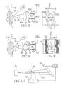
- Figure 1 shows schematically a synchronous optical triangulation scanning system that functions in accordance with the teachings of Rioux U.S. Patent 4,627,734 and is essentially alike in structure to the embodiment illustrated in Figure 12 of such patent.
- a light source 2 e.g. a RGB laser, produces a beam 6 that contains well defined red, green and blue wavelengths. Together with fixed mirrors 10, one surface of an oscillating double-sided mirror 4 scans the beam 6 in the X direction and projects it towards an object 8.
- Light 7 received back from a point P on the target surface of the object 8 is returned by a further fixed mirror 10, the opposite surface of the mirror 4, and a lens 14, in the form of a return beam 12 that is imaged onto a position sensitive detector 18, e.g. a CCD.
- a position sensitive detector 18 e.g. a CCD.
- a device 16 Interposed in this beam 12 is a device 16 for dispersing the beam into separate return beams 12B, 12G and 12R of the three primary colors.
- the dispersal device 16 can be a simple wedge, it is preferable to use either a double wedge or other device that will achieve a collinear effect, at least for one of the beams, preferably the green beam. In other words, the beam 12G will be a straight through continuation of the beam 12. This collinearity is, however, not essential.
- the detector 18 measures the amplitudes A and the positions D of the respective beams 12B, 12G and 12R to generate the signals 17B, 17G and 17R shown in Figure 2.
- the detector 18 is slanted to this optical axis because the focal plane varies with range. Since the positions of the 17R, 17G and 17B signals relative to each other do not vary substantially, any one, two, or all of these signals can be used to measure the Z deviation. Usually the signal with the greatest amplitude will be chosen for this purpose. If the color of the object is such that one of these signals is absent or is too small to measure, the colors of the two remaining signals can be identified by their spacing from each other.
- the detector 18 is two-dimensional, i.e. has pixels extending in the Y direction (perpendicular to both the X and Z directions) as well as in the X direction, the necessary scanning of the beams in the Y direction can conveniently be achieved by means of a further mirror oscillating about an axis extending in the X direction (see the mirror M6 in the Figure 12 of U.S. 4,627,734 referred to above).
- a microprocessor 20 controls by a connection 13 the scanning of the mirror 4 (or the mirrors, if there are more than one), or the relative translation of the object 8 and the camera 19, while receiving and digitizing signals 17B, 17G, 17R on line 15 to produce 3-D color data that can be stored, used to identify the object or used to create a facsimile of it, which data can also be shown on a display 21.
- FIG. 3 A more basic triangulation configuration is shown in Figure 3 wherein a beam 32 from an RGB laser, which beam is scanned in the Y direction by a mechanism (not shown), is projected onto a surface point P of an object 34. After passing through an imaging lens 35 and a dispersing device 38 for splitting the return beam 33 into the three primary colors (not separately shown in Figure 3), such beam is received at M on a linear position sensitive detector 36.
- B is the triangulation angle and the slant of the detector 36 is a straight line projection from a point on the incident beam 32 that is intersected by an extension of the central transverse plane of the lens 32, as shown by the dotted lines.
- Figure 4 shows an embodiment similar to Figure 1 except that the light source 22 produces a beam 6' that is a mixture of a continuum of visible light and laser light of a well defined wavelength, preferably a wavelength, such as infrared, outside the visible spectrum. Alternatively, the wavelength of the laser light can be within the visible spectrum, provided the resulting signal is distinguishable from that resulting from the visible light.
- the corresponding separate return beams 12V and 12I received by the detector 18 now generate respective signals 17V and 17I.
- the signal 17I is used to determine the deviation of the point P in the Z direction while the signal 17V can be broken down into a relatively large number of wavelengths by the microprocessor 20 to enable a much more accurate colorimetric measurement than can be achieved simply from the three primary colors. This system thus makes possible the detection of minor or other subtle color changes of a surface over time or during processing of such surface, e.g. cleaning or otherwise restoring.
- FIG. 6 shows, in simplified form, an embodiment employing the optical configuration shown in Rioux U.S. patent 4,645,347.
- a laser 48 generates a so-called lamina or planar, multiwavelength beam 49, i.e. a beam that has a substantial extent in the Y direction while being very narrow in the X direction, whereby to project a stripe of light onto the surface of the object 8.
- a lens 42 focuses light 45 from the target onto a pair of spaced points on a two-dimensional, position sensitive detector 52, e.g. a CCD array, the spacing between these points being a measure of the Z deviation of the point P from the reference plane.
- each beam is split, as before, into beams 45B, 45G and 45R, the signals seen by the microprocessor 20 being as shown by the three pairs of wavy lines 62B, 62G and 62R in Figure 7.
- the amplitudes of the lines are processed as before to generate data on the color of the target surface, while the spacings D1, D2, etc. at different locations in the Y direction between a selected pair of lines, say the pair of lines 62G, indicates the Z data, i.e. the deviation in range.
- the apparatus will include means for scanning the light beam relative to the object in the X direction.
- Figure 8 shows an embodiment similar to that of Figure 7 but modified to employ a light source 70 for generating a laminar beam 71 that combines the visible continuum with a well defined laser wavelength as in Figure 4.
- the detector 52 receives beams 72V and 72I that have the shapes shown in Figure 9.
- spacings D1, D2 provide the Z data, while the nature of the spectrum 74 indicates the color of the surface.
- Figure 10 shows a modification in which the triangulation method of measuring range and hence the profile of the target surface is replaced by a time of flight (radar) type of system.
- a partial mirror 80 deflects a part of one of the return beams, say the beam 12G, into a detector 81 connected to the microprocessor 20.
- the incident beam is pulsed and the microprocessor measures and digitizes the range on the basis of the detected time of flight of the pulse from emission to return.
- the detector 18 need no longer be slanted to the optical axis, since it is no longer being used to measure range (profile), but it has been shown slanted in Figure 10, because this is its usual orientation in a 3-D camera and one of the features of the present invention is a minimization of changes to the camera.
- the triangulation angle can be reduced to approximately zero, i.e. the incident beam can have an axis approximately parallel to that of the return beam, which is advantageous, especially when the target surface is comparatively remote from the camera.
- the Figure 10 embodiment while calling for more modification to the camera than the methods of Figures 1-9 by virtue of the need for an additional detector 81, has the offsetting advantage of permitting adoption of a zero or very small angle between the axes of the incident and return beams.
Landscapes
- Physics & Mathematics (AREA)
- General Physics & Mathematics (AREA)
- Length Measuring Devices By Optical Means (AREA)
- Measurement Of Optical Distance (AREA)
- Image Processing (AREA)
- Image Generation (AREA)
- Image Analysis (AREA)
Applications Claiming Priority (2)
| Application Number | Priority Date | Filing Date | Title |
|---|---|---|---|
| CA002017518A CA2017518A1 (fr) | 1990-05-24 | 1990-05-24 | Imagerie a determination du spectre de couleurs |
| CA2017518 | 1990-05-25 |
Publications (3)
| Publication Number | Publication Date |
|---|---|
| EP0458168A2 true EP0458168A2 (fr) | 1991-11-27 |
| EP0458168A3 EP0458168A3 (en) | 1992-07-01 |
| EP0458168B1 EP0458168B1 (fr) | 1995-11-02 |
Family
ID=4145062
Family Applications (1)
| Application Number | Title | Priority Date | Filing Date |
|---|---|---|---|
| EP91107790A Expired - Lifetime EP0458168B1 (fr) | 1990-05-24 | 1991-05-14 | Imagerie en couleur tridimensionnelle |
Country Status (5)
| Country | Link |
|---|---|
| US (1) | US5177556A (fr) |
| EP (1) | EP0458168B1 (fr) |
| JP (1) | JP3220179B2 (fr) |
| CA (1) | CA2017518A1 (fr) |
| DE (1) | DE69114181T2 (fr) |
Cited By (5)
| Publication number | Priority date | Publication date | Assignee | Title |
|---|---|---|---|---|
| WO1997033139A1 (fr) * | 1996-03-04 | 1997-09-12 | National Research Council Of Canada | Imagerie tridimensionnelle en couleurs |
| DE19831612A1 (de) * | 1998-07-14 | 2000-01-20 | Voith Sulzer Papiermasch Gmbh | Meßsystem |
| EP0890822A3 (fr) * | 1997-07-09 | 2000-04-05 | YEDA RESEARCH AND DEVELOPMENT Co. LTD. | Procédé de triangulation et système de profilometrie optique codée par couleur |
| EP1028312A1 (fr) * | 1999-02-10 | 2000-08-16 | UMM Electronics, Inc. | Appareil optique pour analyse |
| EP1477765A4 (fr) * | 2002-02-21 | 2009-12-09 | Bridgestone Corp | Procede et dispositif de detection d'un objet, procede et dispositif d'examen d'un objet |
Families Citing this family (37)
| Publication number | Priority date | Publication date | Assignee | Title |
|---|---|---|---|---|
| JP3186799B2 (ja) * | 1991-09-17 | 2001-07-11 | 興和株式会社 | 立体形状測定装置 |
| JPH06102021A (ja) * | 1992-09-21 | 1994-04-12 | Kubota Corp | 三次元形状計測装置 |
| US5627363A (en) * | 1995-02-16 | 1997-05-06 | Environmental Research Institute Of Michigan | System and method for three-dimensional imaging of opaque objects using frequency diversity and an opacity constraint |
| US5701173A (en) * | 1996-02-20 | 1997-12-23 | National Research Council Of Canada | Method and apparatus for reducing the unwanted effects of noise present in a three dimensional color imaging system |
| US6044170A (en) * | 1996-03-21 | 2000-03-28 | Real-Time Geometry Corporation | System and method for rapid shape digitizing and adaptive mesh generation |
| US5870220A (en) * | 1996-07-12 | 1999-02-09 | Real-Time Geometry Corporation | Portable 3-D scanning system and method for rapid shape digitizing and adaptive mesh generation |
| US6122065A (en) * | 1996-08-12 | 2000-09-19 | Centre De Recherche Industrielle Du Quebec | Apparatus and method for detecting surface defects |
| US5708504A (en) * | 1996-10-25 | 1998-01-13 | The United States Of America As Represented By The Secretary Of The Air Force | Interfering imaging spectrometer |
| KR100268048B1 (ko) * | 1996-10-28 | 2000-11-01 | 고바야시 마사키 | 수중레이저영상장치 |
| US5946645A (en) * | 1997-04-09 | 1999-08-31 | National Research Council Of Canada | Three dimensional imaging method and device |
| US5978089A (en) * | 1997-04-15 | 1999-11-02 | Nextel Ltd. | Non-contact method for measuring the shape of an object |
| US6335757B1 (en) | 1997-09-02 | 2002-01-01 | Bojko Vodanovic | CCD imaging device for high speed profiling |
| US6252659B1 (en) * | 1998-03-26 | 2001-06-26 | Minolta Co., Ltd. | Three dimensional measurement apparatus |
| US6549288B1 (en) | 1998-05-14 | 2003-04-15 | Viewpoint Corp. | Structured-light, triangulation-based three-dimensional digitizer |
| US6297488B1 (en) | 1999-04-29 | 2001-10-02 | National Research Council Of Canada | Position sensitive light spot detector |
| US6507036B1 (en) | 1999-06-01 | 2003-01-14 | National Research Council Of Canada | Three dimensional optical scanning |
| US6441908B1 (en) * | 1999-08-06 | 2002-08-27 | Metron Systems, Inc. | Profiling of a component having reduced sensitivity to anomalous off-axis reflections |
| DE19956646C1 (de) * | 1999-11-25 | 2001-10-18 | Dieter Dirksen | Vorrichtung und Verfahren zur Erfassung der Raumkoordinaten von farblich differenzierten Oberflächenmerkmalen |
| US6888640B2 (en) * | 2000-02-04 | 2005-05-03 | Mario J. Spina | Body spatial dimension mapper |
| US7065242B2 (en) * | 2000-03-28 | 2006-06-20 | Viewpoint Corporation | System and method of three-dimensional image capture and modeling |
| US6664529B2 (en) * | 2000-07-19 | 2003-12-16 | Utah State University | 3D multispectral lidar |
| US6410930B1 (en) * | 2000-08-24 | 2002-06-25 | Eastman Kodak Company | Method and apparatus for aligning a color scannerless range imaging system |
| US6724489B2 (en) * | 2000-09-22 | 2004-04-20 | Daniel Freifeld | Three dimensional scanning camera |
| KR100425885B1 (ko) * | 2001-02-16 | 2004-04-03 | 비엔비넷(주) | 3 차원 영상 획득 장치 |
| US6552788B1 (en) * | 2001-07-09 | 2003-04-22 | Ruda & Associates | Hyperspectral imaging using linear chromatic aberration |
| WO2003012371A1 (fr) | 2001-08-01 | 2003-02-13 | National Research Council Of Canada | Systeme et procede de detection de la position et de la couleur d'un point lumineux |
| US20040217956A1 (en) * | 2002-02-28 | 2004-11-04 | Paul Besl | Method and system for processing, compressing, streaming, and interactive rendering of 3D color image data |
| US20040119833A1 (en) * | 2002-07-25 | 2004-06-24 | Duncan Donald D. | Three-dimensional context sensitive scanner |
| US7302174B2 (en) * | 2003-12-31 | 2007-11-27 | Symbol Technologies, Inc. | Method and apparatus for capturing images using a color laser projection display |
| US7698068B2 (en) | 2004-06-17 | 2010-04-13 | Cadent Ltd. | Method for providing data associated with the intraoral cavity |
| EP1610091A1 (fr) * | 2004-06-23 | 2005-12-28 | Leica Geosystems AG | Système et méthode de balayage pour la détection des surfaces |
| US7701558B2 (en) * | 2006-09-22 | 2010-04-20 | Leica Geosystems Ag | LIDAR system |
| DE102009015920B4 (de) * | 2009-03-25 | 2014-11-20 | Faro Technologies, Inc. | Vorrichtung zum optischen Abtasten und Vermessen einer Umgebung |
| US9551575B2 (en) | 2009-03-25 | 2017-01-24 | Faro Technologies, Inc. | Laser scanner having a multi-color light source and real-time color receiver |
| CA2848149C (fr) | 2013-04-12 | 2016-08-30 | Richard Gagnon | Procede et appareil de filtrage de bruit d'image |
| US10222199B2 (en) * | 2014-12-02 | 2019-03-05 | Mitsubishi Electric Corporation | Displacement sensor, displacement detection apparatus, and displacement detection method |
| DE102019218220A1 (de) * | 2019-11-26 | 2021-05-27 | Robert Bosch Gmbh | LIDAR-Sensor und Verfahren zur optischen Erfassung eines Sichtfeldes |
Family Cites Families (9)
| Publication number | Priority date | Publication date | Assignee | Title |
|---|---|---|---|---|
| US4072405A (en) * | 1974-06-13 | 1978-02-07 | Tokina Optical Co., Ltd. | Prism system for use in tricolor separation |
| US4171917A (en) * | 1974-07-02 | 1979-10-23 | Centre De Recherches Metallurgiques-Centrum Voor Research In De Metallurgie | Determining the profile of a surface of an object |
| US3986774A (en) * | 1975-05-08 | 1976-10-19 | United Technologies Corporation | Gauging surfaces by remotely tracking multiple images |
| US4349277A (en) * | 1980-06-11 | 1982-09-14 | General Electric Company | Non-contact measurement of surface profile |
| DE3170315D1 (en) * | 1981-10-09 | 1985-06-05 | Ibm Deutschland | Interpolating light section process |
| NL8302228A (nl) * | 1983-06-22 | 1985-01-16 | Optische Ind De Oude Delft Nv | Meetstelsel voor het onder gebruikmaking van een op driehoeksmeting berustend principe, contactloos meten van een door een oppervlakcontour van een objectvlak gegeven afstand tot een referentieniveau. |
| US4627734A (en) * | 1983-06-30 | 1986-12-09 | Canadian Patents And Development Limited | Three dimensional imaging method and device |
| US4645347A (en) * | 1985-04-30 | 1987-02-24 | Canadian Patents And Development Limited-Societe Canadienne Des Brevets Et D'exploitation Limitee | Three dimensional imaging device |
| US4954972A (en) * | 1987-11-09 | 1990-09-04 | Honeywell Inc. | Color signature sensor |
-
1990
- 1990-05-24 CA CA002017518A patent/CA2017518A1/fr not_active Abandoned
-
1991
- 1991-05-14 DE DE69114181T patent/DE69114181T2/de not_active Expired - Lifetime
- 1991-05-14 EP EP91107790A patent/EP0458168B1/fr not_active Expired - Lifetime
- 1991-05-22 JP JP11737891A patent/JP3220179B2/ja not_active Expired - Lifetime
- 1991-05-22 US US07/704,092 patent/US5177556A/en not_active Expired - Lifetime
Cited By (6)
| Publication number | Priority date | Publication date | Assignee | Title |
|---|---|---|---|---|
| WO1997033139A1 (fr) * | 1996-03-04 | 1997-09-12 | National Research Council Of Canada | Imagerie tridimensionnelle en couleurs |
| EP0890822A3 (fr) * | 1997-07-09 | 2000-04-05 | YEDA RESEARCH AND DEVELOPMENT Co. LTD. | Procédé de triangulation et système de profilometrie optique codée par couleur |
| DE19831612A1 (de) * | 1998-07-14 | 2000-01-20 | Voith Sulzer Papiermasch Gmbh | Meßsystem |
| US6526369B1 (en) | 1998-07-14 | 2003-02-25 | Voith Sulzer Papiertechnik Patent Gmbh | Apparatus and process for a cross-direction profile of a material web |
| EP1028312A1 (fr) * | 1999-02-10 | 2000-08-16 | UMM Electronics, Inc. | Appareil optique pour analyse |
| EP1477765A4 (fr) * | 2002-02-21 | 2009-12-09 | Bridgestone Corp | Procede et dispositif de detection d'un objet, procede et dispositif d'examen d'un objet |
Also Published As
| Publication number | Publication date |
|---|---|
| EP0458168B1 (fr) | 1995-11-02 |
| CA2017518A1 (fr) | 1991-11-24 |
| DE69114181T2 (de) | 1996-07-18 |
| US5177556A (en) | 1993-01-05 |
| DE69114181D1 (de) | 1995-12-07 |
| EP0458168A3 (en) | 1992-07-01 |
| JPH04232580A (ja) | 1992-08-20 |
| JP3220179B2 (ja) | 2001-10-22 |
Similar Documents
| Publication | Publication Date | Title |
|---|---|---|
| US5177556A (en) | Three dimensional color imaging | |
| US5675407A (en) | Color ranging method for high speed low-cost three dimensional surface profile measurement | |
| US6147760A (en) | High speed three dimensional imaging method | |
| US5708498A (en) | Three dimensional color imaging | |
| US6765606B1 (en) | Three dimension imaging by dual wavelength triangulation | |
| JPH0574764B2 (fr) | ||
| JP2510786B2 (ja) | 物体の形状検出方法及びその装置 | |
| CA2334225C (fr) | Procede et dispositif d'acquisition opto-electrique de formes par illumination axiale | |
| US5701173A (en) | Method and apparatus for reducing the unwanted effects of noise present in a three dimensional color imaging system | |
| US5940566A (en) | 3D array optical displacement sensor and method using same | |
| US6373561B2 (en) | Device and method for detecting depth and color information of an object to be surveyed | |
| CA2043336C (fr) | Imagerie en couleurs tridimensionnelle | |
| US20030142324A1 (en) | Optoelectronic measuring method and distance measuring device for carrying out the method | |
| JPH04110707A (ja) | 三次元形状計測装置 | |
| JPH04110706A (ja) | 三次元形状データ取込み装置 | |
| JP2000002521A (ja) | 3次元入力装置 | |
| JP2689167B2 (ja) | 粒度分布測定装置 | |
| US20010000021A1 (en) | Optoelectronic measuring method and distance measuring device for carrying out the method | |
| JPH0789057B2 (ja) | 距離測定装置 | |
| JPH0518726A (ja) | カラー三次元画像入力装置 | |
| JPH05199999A (ja) | 走査型眼底カメラ | |
| DE19624751A1 (de) | Laufzeitmessung mit kontinuierlich emittiertem Lichtstrahl | |
| JPH03248005A (ja) | 形状計測装置 | |
| JPH06213633A (ja) | 三次元形状計測装置 |
Legal Events
| Date | Code | Title | Description |
|---|---|---|---|
| PUAI | Public reference made under article 153(3) epc to a published international application that has entered the european phase |
Free format text: ORIGINAL CODE: 0009012 |
|
| AK | Designated contracting states |
Kind code of ref document: A2 Designated state(s): DE FR GB |
|
| PUAL | Search report despatched |
Free format text: ORIGINAL CODE: 0009013 |
|
| AK | Designated contracting states |
Kind code of ref document: A3 Designated state(s): DE FR GB |
|
| 17P | Request for examination filed |
Effective date: 19921217 |
|
| 17Q | First examination report despatched |
Effective date: 19940301 |
|
| GRAA | (expected) grant |
Free format text: ORIGINAL CODE: 0009210 |
|
| AK | Designated contracting states |
Kind code of ref document: B1 Designated state(s): DE FR GB |
|
| REF | Corresponds to: |
Ref document number: 69114181 Country of ref document: DE Date of ref document: 19951207 |
|
| ET | Fr: translation filed | ||
| PLBE | No opposition filed within time limit |
Free format text: ORIGINAL CODE: 0009261 |
|
| STAA | Information on the status of an ep patent application or granted ep patent |
Free format text: STATUS: NO OPPOSITION FILED WITHIN TIME LIMIT |
|
| 26N | No opposition filed | ||
| REG | Reference to a national code |
Ref country code: GB Ref legal event code: IF02 |
|
| PGFP | Annual fee paid to national office [announced via postgrant information from national office to epo] |
Ref country code: FR Payment date: 20100525 Year of fee payment: 20 |
|
| PGFP | Annual fee paid to national office [announced via postgrant information from national office to epo] |
Ref country code: GB Payment date: 20100512 Year of fee payment: 20 Ref country code: DE Payment date: 20100727 Year of fee payment: 20 |
|
| REG | Reference to a national code |
Ref country code: DE Ref legal event code: R071 Ref document number: 69114181 Country of ref document: DE |
|
| REG | Reference to a national code |
Ref country code: GB Ref legal event code: PE20 Expiry date: 20110513 |
|
| PG25 | Lapsed in a contracting state [announced via postgrant information from national office to epo] |
Ref country code: GB Free format text: LAPSE BECAUSE OF EXPIRATION OF PROTECTION Effective date: 20110513 |
|
| PG25 | Lapsed in a contracting state [announced via postgrant information from national office to epo] |
Ref country code: DE Free format text: LAPSE BECAUSE OF EXPIRATION OF PROTECTION Effective date: 20110514 |