EP0458236A1 - Mittelspannungsschalter - Google Patents
Mittelspannungsschalter Download PDFInfo
- Publication number
- EP0458236A1 EP0458236A1 EP91108128A EP91108128A EP0458236A1 EP 0458236 A1 EP0458236 A1 EP 0458236A1 EP 91108128 A EP91108128 A EP 91108128A EP 91108128 A EP91108128 A EP 91108128A EP 0458236 A1 EP0458236 A1 EP 0458236A1
- Authority
- EP
- European Patent Office
- Prior art keywords
- volume
- circuit breaker
- contact
- piston
- semi
- Prior art date
- Legal status (The legal status is an assumption and is not a legal conclusion. Google has not performed a legal analysis and makes no representation as to the accuracy of the status listed.)
- Granted
Links
Images


Classifications
-
- H—ELECTRICITY
- H01—ELECTRIC ELEMENTS
- H01H—ELECTRIC SWITCHES; RELAYS; SELECTORS; EMERGENCY PROTECTIVE DEVICES
- H01H33/00—High-tension or heavy-current switches with arc-extinguishing or arc-preventing means
- H01H33/70—Switches with separate means for directing, obtaining, or increasing flow of arc-extinguishing fluid
- H01H33/88—Switches with separate means for directing, obtaining, or increasing flow of arc-extinguishing fluid the flow of arc-extinguishing fluid being produced or increased by movement of pistons or other pressure-producing parts
- H01H33/90—Switches with separate means for directing, obtaining, or increasing flow of arc-extinguishing fluid the flow of arc-extinguishing fluid being produced or increased by movement of pistons or other pressure-producing parts this movement being effected by or in conjunction with the contact-operating mechanism
- H01H33/901—Switches with separate means for directing, obtaining, or increasing flow of arc-extinguishing fluid the flow of arc-extinguishing fluid being produced or increased by movement of pistons or other pressure-producing parts this movement being effected by or in conjunction with the contact-operating mechanism making use of the energy of the arc or an auxiliary arc
Definitions
- the present invention relates to a medium voltage circuit breaker in which the electrical insulation is ensured by a gas with good dielectric properties, such as sulfur hexafluoride, (SF6).
- a gas with good dielectric properties such as sulfur hexafluoride, (SF6).
- Thermal volume Medium voltage circuit breakers are known in which there is a thermal expansion volume (abbreviated as thermal volume) whose gas, heated by the arc which develops at the separation of the arcing contacts, expands as it passes zero current and blows the arc.
- the displacement of the piston is more or less important, so that the thermal volume is more or less large.
- Such a device has a drawback.
- An object of the present invention is to provide a medium voltage circuit breaker which does not have this drawback.
- Another object of the invention is to provide a circuit breaker in which, for cutting the currents of high intensity, a double blowing is carried out, that is to say a blowing on each of the roots of the arc.
- Another object of the invention is to provide a circuit breaker in which the thermal expansion of the gas is limited, so as to reduce the risks of failure to cut.
- the medium-voltage circuit breaker of the invention which comprises a sealed insulating envelope filled with a gas having good dielectric properties, a semi-fixed arcing contact electrically connected to a first socket and a movable contact connected to an operating mechanism and electrically connected to a second socket, characterized in that the semi-fixed arcing contact is linked to a piston which can move in a blowing volume delimited in particular by the inner wall d an insulating cylinder inside said casing and a first face of a blowing nozzle, said piston being pushed by a spring kept bandaged when the circuit breaker is in the engaged position, said circuit breaker comprising a volume of thermal expansion delimited in particular by the wall inside of said cylinder a second face of the nozzle and a transverse partition through which slides the movable contact, m oyens being provided so that, during a high current cut, the piston cannot, after having performed its stroke in the direction of compression of the blowing volume, move in the other direction.
- the means so that the piston cannot move in the other direction are constituted by a passage section (se) between the neck of the nozzle and the blowing volume less than the total section of the other passages offered to the gas escaping from the thermal expansion volume.
- the semi-mobile contact is a tubular contact putting the blowing volume into communication with the volume located at the rear of the piston.
- the semi-mobile contact is a solid rod.
- the movable contact is a tubular contact.
- the movable contact has at least one bore placed so as to allow communication between the end of this contact on the nozzle side and the interior of the thermal expansion volume, during part of the stroke of this contact during a circuit breaker tripping operation.
- the insulating cylinder includes holes to allow communication between the volume located at the rear of the piston and the volume between said cylinder and said casing.
- the reference 1 designates a sealed envelope of insulating material, filled with a gas with good dielectric properties such as sulfur hexafluoride, under a pressure of 1 to a few bars absolute.
- the envelope is closed at its upper part by a plate metallic 2 extended to form a first circuit breaker socket.
- This socket is electrically connected by a flexible metal braid 18 to a metal piston 4 carrying a metal tubular contact 3, the end 3A of which is made of an alloy resistant to the effects of the electric arc, for example based on tungsten.
- This contact 3 is designated in the following by semi-mobile contact.
- the piston can slide in a cylindrical volume delimited by an insulating cylinder 8 extending, inside the envelope, coaxially with the latter, and constituting a wall of the breaking chamber.
- the piston is moved under the action of a powerful spring 9 which is supported on the plate 2.
- the piston is provided with a one-way valve 5 which lets the gas pass only in the direction going from the volume V3, spring side , to the blowing volume V1 which will be defined later. This valve opens when the circuit breaker is closed and prevents compression of the gas in volume V3.
- the blowing volume V1 is delimited by the piston 4, the inner wall of the cylinder 8 and a face 7A of an insulating nozzle 7 having a neck 7C.
- the movable contact of the circuit breaker consists of a metal tube 10 terminated at a first end by an end piece of material resistant to the effects of the arc and connected by a second end to an operating rod 13 made of insulating material.
- This rod is conventionally connected to an operating mechanism.
- the tubular contact 10 crosses the neck of the nozzle with gentle friction when the circuit breaker is in the on position, as shown in FIG. 1.
- a thermal expansion volume V2 is constituted by the interior wall of the cylinder 8, the second face 7B of the nozzle 7 and a metal transverse partitions 11, extended outside the casing 1 to constitute the second outlet of the circuit breaker.
- a sliding electrical contact 12 ensures the electrical connection between the tube 10 and the socket 11.
- the tube 10 is preferably guided by a metal partition or transverse insulator 15 provided with large openings 16 for the passage of gas.
- An insulating part 7D allows better guidance of the gas threads; it can be attached and fixed to the partition 16 or be an integral part of the nozzle.
- the cut is made by autopneumatic blowing of the arc near the semi-mobile contact 3 by expansion of the gas of the blowing volume V1.
- the pressure in the volume V1 mainly results from the compression of the piston 4 and for a very small part from the heating of the gas by the arc.
- the force of the spring 9 always remains greater than the opposing force due to the overpressure; consequently, the piston 4 does not go up during the triggering.
- the gas supply to volume V3, located behind the piston is ensured by the openings 20 and also by the fact that the semi-mobile contact is a tube. This avoids a depression behind the piston which would lead to additional consumption of operating energy.
- FIG. 3 shows a variant in which the semi-mobile contact is a solid rod 30. This arrangement allows a simpler construction while giving the circuit breaker practically the same breaking qualities.
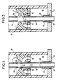
- FIGS. 4 and 5 illustrate an alternative embodiment in which holes 40 are made in the tubular movable contact 10.
- the invention applies to the construction of medium-voltage circuit breakers, for example up to 45kV.
Landscapes
- Circuit Breakers (AREA)
- Emergency Protection Circuit Devices (AREA)
- Electrical Discharge Machining, Electrochemical Machining, And Combined Machining (AREA)
- Switches That Are Operated By Magnetic Or Electric Fields (AREA)
- Seal Device For Vehicle (AREA)
- Electrophonic Musical Instruments (AREA)
- Driving Mechanisms And Operating Circuits Of Arc-Extinguishing High-Tension Switches (AREA)
- Superconductors And Manufacturing Methods Therefor (AREA)
Applications Claiming Priority (2)
| Application Number | Priority Date | Filing Date | Title |
|---|---|---|---|
| FR9006458A FR2662540B1 (fr) | 1990-05-23 | 1990-05-23 | Disjoncteur a moyenne tension. |
| FR9006458 | 1990-05-23 |
Publications (2)
| Publication Number | Publication Date |
|---|---|
| EP0458236A1 true EP0458236A1 (de) | 1991-11-27 |
| EP0458236B1 EP0458236B1 (de) | 1995-01-04 |
Family
ID=9396894
Family Applications (1)
| Application Number | Title | Priority Date | Filing Date |
|---|---|---|---|
| EP91108128A Expired - Lifetime EP0458236B1 (de) | 1990-05-23 | 1991-05-21 | Mittelspannungsschalter |
Country Status (12)
| Country | Link |
|---|---|
| US (1) | US5155313A (de) |
| EP (1) | EP0458236B1 (de) |
| JP (1) | JP2563856B2 (de) |
| CN (1) | CN1023737C (de) |
| AT (1) | ATE116764T1 (de) |
| BR (1) | BR9102093A (de) |
| CA (1) | CA2043025C (de) |
| DE (1) | DE69106436T2 (de) |
| DK (1) | DK0458236T3 (de) |
| ES (1) | ES2067796T3 (de) |
| FR (1) | FR2662540B1 (de) |
| GR (1) | GR3015385T3 (de) |
Cited By (1)
| Publication number | Priority date | Publication date | Assignee | Title |
|---|---|---|---|---|
| EP2387057A1 (de) * | 2010-05-12 | 2011-11-16 | ABB Technology AG | Gasisolierter Hochspannungsschalter |
Families Citing this family (4)
| Publication number | Priority date | Publication date | Assignee | Title |
|---|---|---|---|---|
| FR2683383B1 (fr) * | 1991-11-04 | 1993-12-31 | Gec Alsthom Sa | Disjoncteur a haute ou moyenne tension a triple mouvement. |
| EP2325859B1 (de) * | 2009-11-24 | 2013-04-17 | ABB Technology AG | Gasisolierter Hochspannungsschalter |
| KR101116388B1 (ko) * | 2010-10-15 | 2012-03-09 | 엘에스산전 주식회사 | 전자 개폐장치 |
| EP3094350B1 (de) | 2014-01-15 | 2020-03-04 | The U.S.A. as represented by the Secretary, Department of Health and Human Services | Auf knorpel gerichtete wirkstoffe und deren verwendung |
Citations (4)
| Publication number | Priority date | Publication date | Assignee | Title |
|---|---|---|---|---|
| FR2356258A1 (fr) * | 1976-06-24 | 1978-01-20 | Sprecher & Schuh Ag | Disjoncteur a gaz comprime |
| EP0149470A2 (de) * | 1984-01-13 | 1985-07-24 | Alsthom | Hochspannungsschalter mit Lichtbogenbeblasung |
| DE3727802A1 (de) * | 1987-08-20 | 1989-03-02 | Licentia Gmbh | Selbstloeschender druckgasschalter |
| EP0315505A1 (de) * | 1987-11-04 | 1989-05-10 | Merlin Gerin | Elektrischer selbstgeblasener Lastschalter mit veränderlichem Löschkammervolumen |
Family Cites Families (10)
| Publication number | Priority date | Publication date | Assignee | Title |
|---|---|---|---|---|
| DE2759267C3 (de) * | 1977-12-30 | 1980-09-11 | Siemens Ag, 1000 Berlin Und 8000 Muenchen | Druckgasschalter |
| JPS5856926B2 (ja) * | 1978-08-19 | 1983-12-17 | 三菱電機株式会社 | 自力消弧形開閉装置 |
| JPS5553824A (en) * | 1978-10-17 | 1980-04-19 | Mitsubishi Electric Corp | Gas switch |
| JPS5535437A (en) * | 1978-09-04 | 1980-03-12 | Mitsubishi Electric Corp | Switch |
| CH646011A5 (de) * | 1979-04-12 | 1984-10-31 | Sprecher & Schuh Ag | Druckgasschalter. |
| US4327263A (en) * | 1980-06-17 | 1982-04-27 | Mitsubishi Denke Kabushiki Kaisha | Switching device |
| JPS57180026A (en) * | 1981-04-24 | 1982-11-05 | Mitsubishi Electric Corp | Gas breaker |
| JPS5933725A (ja) * | 1982-08-17 | 1984-02-23 | 株式会社東芝 | 開閉器 |
| JPS5944735A (ja) * | 1982-09-07 | 1984-03-13 | 株式会社東芝 | 開閉器 |
| IT1173099B (it) * | 1984-01-20 | 1987-06-18 | Sace Spa | Interruttore elettrico a fluido compresso di estinzione dell'arco |
-
1990
- 1990-05-23 FR FR9006458A patent/FR2662540B1/fr not_active Expired - Lifetime
-
1991
- 1991-04-26 US US07/691,874 patent/US5155313A/en not_active Expired - Fee Related
- 1991-05-10 CN CN91103020.4A patent/CN1023737C/zh not_active Expired - Fee Related
- 1991-05-21 DE DE69106436T patent/DE69106436T2/de not_active Expired - Fee Related
- 1991-05-21 BR BR919102093A patent/BR9102093A/pt not_active IP Right Cessation
- 1991-05-21 ES ES91108128T patent/ES2067796T3/es not_active Expired - Lifetime
- 1991-05-21 AT AT91108128T patent/ATE116764T1/de not_active IP Right Cessation
- 1991-05-21 DK DK91108128.9T patent/DK0458236T3/da active
- 1991-05-21 JP JP3116281A patent/JP2563856B2/ja not_active Expired - Lifetime
- 1991-05-21 EP EP91108128A patent/EP0458236B1/de not_active Expired - Lifetime
- 1991-05-22 CA CA002043025A patent/CA2043025C/fr not_active Expired - Fee Related
-
1995
- 1995-03-13 GR GR950400538T patent/GR3015385T3/el unknown
Patent Citations (4)
| Publication number | Priority date | Publication date | Assignee | Title |
|---|---|---|---|---|
| FR2356258A1 (fr) * | 1976-06-24 | 1978-01-20 | Sprecher & Schuh Ag | Disjoncteur a gaz comprime |
| EP0149470A2 (de) * | 1984-01-13 | 1985-07-24 | Alsthom | Hochspannungsschalter mit Lichtbogenbeblasung |
| DE3727802A1 (de) * | 1987-08-20 | 1989-03-02 | Licentia Gmbh | Selbstloeschender druckgasschalter |
| EP0315505A1 (de) * | 1987-11-04 | 1989-05-10 | Merlin Gerin | Elektrischer selbstgeblasener Lastschalter mit veränderlichem Löschkammervolumen |
Cited By (2)
| Publication number | Priority date | Publication date | Assignee | Title |
|---|---|---|---|---|
| EP2387057A1 (de) * | 2010-05-12 | 2011-11-16 | ABB Technology AG | Gasisolierter Hochspannungsschalter |
| US8766131B2 (en) | 2010-05-12 | 2014-07-01 | Abb Technology Ag | Gas-insulated high-voltage switch |
Also Published As
| Publication number | Publication date |
|---|---|
| EP0458236B1 (de) | 1995-01-04 |
| ATE116764T1 (de) | 1995-01-15 |
| CA2043025C (fr) | 1994-11-22 |
| CN1023737C (zh) | 1994-02-09 |
| JP2563856B2 (ja) | 1996-12-18 |
| US5155313A (en) | 1992-10-13 |
| BR9102093A (pt) | 1991-12-24 |
| CA2043025A1 (fr) | 1991-11-24 |
| GR3015385T3 (en) | 1995-06-30 |
| DK0458236T3 (da) | 1995-05-22 |
| FR2662540B1 (fr) | 1992-07-31 |
| JPH04280016A (ja) | 1992-10-06 |
| CN1056371A (zh) | 1991-11-20 |
| ES2067796T3 (es) | 1995-04-01 |
| DE69106436T2 (de) | 1995-05-11 |
| DE69106436D1 (de) | 1995-02-16 |
| FR2662540A1 (fr) | 1991-11-29 |
Similar Documents
| Publication | Publication Date | Title |
|---|---|---|
| EP0315505A1 (de) | Elektrischer selbstgeblasener Lastschalter mit veränderlichem Löschkammervolumen | |
| FR2677168A1 (fr) | Disjoncteur moyenne tension a energie de commande reduite. | |
| FR2814588A1 (fr) | Interrupteur de circuit possedant une fonction hybride d'extinction d'arc | |
| CA2035688C (fr) | Disjoncteur a moyenne ou haute tension a autosoufflage | |
| FR2512267A1 (fr) | Disjoncteur a gaz comprime muni de resistances d'ouverture et de fermeture | |
| EP0240397A1 (de) | Selbstbeblasender elektrischer Lastschalter mit rotierendem Lichtbogen | |
| FR2638564A1 (fr) | Disjoncteur a haute tension a gaz dielectrique sous pression | |
| EP0458236B1 (de) | Mittelspannungsschalter | |
| EP0185576A1 (de) | Elektrischer Schalter mit Schirm | |
| FR2576144A1 (fr) | Disjoncteur a haute tension, a gaz comprime, a faible energie de manoeuvre | |
| EP0415098B1 (de) | Selbstblasschalter für Mittelspannung | |
| EP0759629B1 (de) | Lastschalter mit Einschaltwiderstand und Einfügungsvorrichtung | |
| EP0334181A1 (de) | Hochspannungsschalter mit geringer Antriebsenergie | |
| EP0450567B1 (de) | Hoch- oder Mittelspannungs-Schalter mit aufeinanderstossenden Lichtbogenkontakten | |
| CA2041234C (fr) | Disjoncteur a haute tension a arc serie | |
| EP0398213B1 (de) | Mittelspannungsschalter für hohen Nennstrom | |
| FR2679375A1 (fr) | Contact pour disjoncteur. | |
| EP0515268A1 (de) | Varistor Einführvorrichtung, eingebaut in einem Hochspannungslastschalter | |
| FR2535518A1 (fr) | Chambre de coupure pour disjoncteur a gaz | |
| FR2554273A1 (fr) | Disjoncteur de puissance a haute tension | |
| CH634687A5 (en) | Rotating-arc and self-blasting high-voltage circuit breaker | |
| FR2783088A1 (fr) | Interrupteur avec un systeme d'insertion d'une resistance a longue duree d'insertion | |
| FR2683937A1 (fr) | Disjoncteur hybride pour la coupure des courants a grande composante continue. | |
| FR2694987A1 (fr) | Disjoncteur à haute tension ayant une chambre de coupure à volume de soufflage variable. | |
| FR2509521A1 (fr) | Disjoncteur a haute tension sous enveloppe contenant un gaz isolant |
Legal Events
| Date | Code | Title | Description |
|---|---|---|---|
| PUAI | Public reference made under article 153(3) epc to a published international application that has entered the european phase |
Free format text: ORIGINAL CODE: 0009012 |
|
| AK | Designated contracting states |
Kind code of ref document: A1 Designated state(s): AT BE CH DE DK ES FR GB GR IT LI LU NL SE |
|
| 17P | Request for examination filed |
Effective date: 19920518 |
|
| 17Q | First examination report despatched |
Effective date: 19940308 |
|
| GRAA | (expected) grant |
Free format text: ORIGINAL CODE: 0009210 |
|
| AK | Designated contracting states |
Kind code of ref document: B1 Designated state(s): AT BE CH DE DK ES FR GB GR IT LI LU NL SE |
|
| REF | Corresponds to: |
Ref document number: 116764 Country of ref document: AT Date of ref document: 19950115 Kind code of ref document: T |
|
| REF | Corresponds to: |
Ref document number: 69106436 Country of ref document: DE Date of ref document: 19950216 |
|
| ITF | It: translation for a ep patent filed | ||
| GBT | Gb: translation of ep patent filed (gb section 77(6)(a)/1977) |
Effective date: 19950217 |
|
| REG | Reference to a national code |
Ref country code: ES Ref legal event code: FG2A Ref document number: 2067796 Country of ref document: ES Kind code of ref document: T3 |
|
| REG | Reference to a national code |
Ref country code: DK Ref legal event code: T3 |
|
| REG | Reference to a national code |
Ref country code: GR Ref legal event code: FG4A Free format text: 3015385 |
|
| PLBE | No opposition filed within time limit |
Free format text: ORIGINAL CODE: 0009261 |
|
| STAA | Information on the status of an ep patent application or granted ep patent |
Free format text: STATUS: NO OPPOSITION FILED WITHIN TIME LIMIT |
|
| 26N | No opposition filed | ||
| PGFP | Annual fee paid to national office [announced via postgrant information from national office to epo] |
Ref country code: GB Payment date: 19990413 Year of fee payment: 9 |
|
| PGFP | Annual fee paid to national office [announced via postgrant information from national office to epo] |
Ref country code: FR Payment date: 19990419 Year of fee payment: 9 |
|
| PGFP | Annual fee paid to national office [announced via postgrant information from national office to epo] |
Ref country code: DE Payment date: 19990420 Year of fee payment: 9 |
|
| PGFP | Annual fee paid to national office [announced via postgrant information from national office to epo] |
Ref country code: SE Payment date: 19990421 Year of fee payment: 9 Ref country code: DK Payment date: 19990421 Year of fee payment: 9 Ref country code: CH Payment date: 19990421 Year of fee payment: 9 |
|
| PGFP | Annual fee paid to national office [announced via postgrant information from national office to epo] |
Ref country code: AT Payment date: 19990422 Year of fee payment: 9 |
|
| PGFP | Annual fee paid to national office [announced via postgrant information from national office to epo] |
Ref country code: BE Payment date: 19990426 Year of fee payment: 9 |
|
| PGFP | Annual fee paid to national office [announced via postgrant information from national office to epo] |
Ref country code: NL Payment date: 19990427 Year of fee payment: 9 |
|
| PGFP | Annual fee paid to national office [announced via postgrant information from national office to epo] |
Ref country code: LU Payment date: 19990428 Year of fee payment: 9 |
|
| PGFP | Annual fee paid to national office [announced via postgrant information from national office to epo] |
Ref country code: ES Payment date: 19990521 Year of fee payment: 9 |
|
| PGFP | Annual fee paid to national office [announced via postgrant information from national office to epo] |
Ref country code: GR Payment date: 19990526 Year of fee payment: 9 |
|
| PG25 | Lapsed in a contracting state [announced via postgrant information from national office to epo] |
Ref country code: LU Free format text: LAPSE BECAUSE OF NON-PAYMENT OF DUE FEES Effective date: 20000521 Ref country code: GB Free format text: LAPSE BECAUSE OF NON-PAYMENT OF DUE FEES Effective date: 20000521 Ref country code: DK Free format text: LAPSE BECAUSE OF NON-PAYMENT OF DUE FEES Effective date: 20000521 Ref country code: AT Free format text: LAPSE BECAUSE OF NON-PAYMENT OF DUE FEES Effective date: 20000521 |
|
| PG25 | Lapsed in a contracting state [announced via postgrant information from national office to epo] |
Ref country code: SE Free format text: LAPSE BECAUSE OF NON-PAYMENT OF DUE FEES Effective date: 20000522 Ref country code: ES Free format text: THE PATENT HAS BEEN ANNULLED BY A DECISION OF A NATIONAL AUTHORITY Effective date: 20000522 |
|
| PG25 | Lapsed in a contracting state [announced via postgrant information from national office to epo] |
Ref country code: LI Free format text: LAPSE BECAUSE OF NON-PAYMENT OF DUE FEES Effective date: 20000531 Ref country code: GR Free format text: LAPSE BECAUSE OF NON-PAYMENT OF DUE FEES Effective date: 20000531 Ref country code: CH Free format text: LAPSE BECAUSE OF NON-PAYMENT OF DUE FEES Effective date: 20000531 Ref country code: BE Free format text: LAPSE BECAUSE OF NON-PAYMENT OF DUE FEES Effective date: 20000531 |
|
| BERE | Be: lapsed |
Owner name: S.A. GEC ALSTHOM Effective date: 20000531 |
|
| PG25 | Lapsed in a contracting state [announced via postgrant information from national office to epo] |
Ref country code: NL Free format text: LAPSE BECAUSE OF NON-PAYMENT OF DUE FEES Effective date: 20001201 |
|
| GBPC | Gb: european patent ceased through non-payment of renewal fee |
Effective date: 20000521 |
|
| REG | Reference to a national code |
Ref country code: CH Ref legal event code: PL |
|
| EUG | Se: european patent has lapsed |
Ref document number: 91108128.9 |
|
| REG | Reference to a national code |
Ref country code: DK Ref legal event code: EBP |
|
| PG25 | Lapsed in a contracting state [announced via postgrant information from national office to epo] |
Ref country code: FR Free format text: LAPSE BECAUSE OF NON-PAYMENT OF DUE FEES Effective date: 20010131 |
|
| NLV4 | Nl: lapsed or anulled due to non-payment of the annual fee |
Effective date: 20001201 |
|
| PG25 | Lapsed in a contracting state [announced via postgrant information from national office to epo] |
Ref country code: DE Free format text: LAPSE BECAUSE OF NON-PAYMENT OF DUE FEES Effective date: 20010301 |
|
| REG | Reference to a national code |
Ref country code: FR Ref legal event code: ST |
|
| REG | Reference to a national code |
Ref country code: ES Ref legal event code: FD2A Effective date: 20020204 |
|
| PG25 | Lapsed in a contracting state [announced via postgrant information from national office to epo] |
Ref country code: IT Free format text: LAPSE BECAUSE OF NON-PAYMENT OF DUE FEES;WARNING: LAPSES OF ITALIAN PATENTS WITH EFFECTIVE DATE BEFORE 2007 MAY HAVE OCCURRED AT ANY TIME BEFORE 2007. THE CORRECT EFFECTIVE DATE MAY BE DIFFERENT FROM THE ONE RECORDED. Effective date: 20050521 |