EP0458250A2 - Procédé et dispositif de démoulage de la bande de garantie d'un capuchon de fermeture - Google Patents
Procédé et dispositif de démoulage de la bande de garantie d'un capuchon de fermeture Download PDFInfo
- Publication number
- EP0458250A2 EP0458250A2 EP91108155A EP91108155A EP0458250A2 EP 0458250 A2 EP0458250 A2 EP 0458250A2 EP 91108155 A EP91108155 A EP 91108155A EP 91108155 A EP91108155 A EP 91108155A EP 0458250 A2 EP0458250 A2 EP 0458250A2
- Authority
- EP
- European Patent Office
- Prior art keywords
- guarantee
- guarantee band
- demolding
- ring
- mold
- Prior art date
- Legal status (The legal status is an assumption and is not a legal conclusion. Google has not performed a legal analysis and makes no representation as to the accuracy of the status listed.)
- Granted
Links
Images

Classifications
-
- B—PERFORMING OPERATIONS; TRANSPORTING
- B29—WORKING OF PLASTICS; WORKING OF SUBSTANCES IN A PLASTIC STATE IN GENERAL
- B29C—SHAPING OR JOINING OF PLASTICS; SHAPING OF MATERIAL IN A PLASTIC STATE, NOT OTHERWISE PROVIDED FOR; AFTER-TREATMENT OF THE SHAPED PRODUCTS, e.g. REPAIRING
- B29C45/00—Injection moulding, i.e. forcing the required volume of moulding material through a nozzle into a closed mould; Apparatus therefor
- B29C45/17—Component parts, details or accessories; Auxiliary operations
- B29C45/40—Removing or ejecting moulded articles
- B29C45/44—Removing or ejecting moulded articles for undercut articles
- B29C45/4407—Removing or ejecting moulded articles for undercut articles by flexible movement of undercut portions of the articles
-
- B—PERFORMING OPERATIONS; TRANSPORTING
- B65—CONVEYING; PACKING; STORING; HANDLING THIN OR FILAMENTARY MATERIAL
- B65D—CONTAINERS FOR STORAGE OR TRANSPORT OF ARTICLES OR MATERIALS, e.g. BAGS, BARRELS, BOTTLES, BOXES, CANS, CARTONS, CRATES, DRUMS, JARS, TANKS, HOPPERS, FORWARDING CONTAINERS; ACCESSORIES, CLOSURES, OR FITTINGS THEREFOR; PACKAGING ELEMENTS; PACKAGES
- B65D41/00—Caps, e.g. crown caps or crown seals, i.e. members having parts arranged for engagement with the external periphery of a neck or wall defining a pouring opening or discharge aperture; Protective cap-like covers for closure members, e.g. decorative covers of metal foil or paper
- B65D41/32—Caps or cap-like covers with lines of weakness, tearing-strips, tags, or like opening or removal devices, e.g. to facilitate formation of pouring openings
- B65D41/34—Threaded or like caps or cap-like covers provided with tamper elements formed in, or attached to, the closure skirt
- B65D41/3442—Threaded or like caps or cap-like covers provided with tamper elements formed in, or attached to, the closure skirt with rigid bead or projections formed on the tamper element and coacting with bead or projections on the container
- B65D41/3447—Threaded or like caps or cap-like covers provided with tamper elements formed in, or attached to, the closure skirt with rigid bead or projections formed on the tamper element and coacting with bead or projections on the container the tamper element being integrally connected to the closure by means of bridges
-
- B—PERFORMING OPERATIONS; TRANSPORTING
- B29—WORKING OF PLASTICS; WORKING OF SUBSTANCES IN A PLASTIC STATE IN GENERAL
- B29C—SHAPING OR JOINING OF PLASTICS; SHAPING OF MATERIAL IN A PLASTIC STATE, NOT OTHERWISE PROVIDED FOR; AFTER-TREATMENT OF THE SHAPED PRODUCTS, e.g. REPAIRING
- B29C45/00—Injection moulding, i.e. forcing the required volume of moulding material through a nozzle into a closed mould; Apparatus therefor
- B29C45/17—Component parts, details or accessories; Auxiliary operations
- B29C45/40—Removing or ejecting moulded articles
- B29C2045/4078—Removing or ejecting moulded articles using stripping means
-
- B—PERFORMING OPERATIONS; TRANSPORTING
- B29—WORKING OF PLASTICS; WORKING OF SUBSTANCES IN A PLASTIC STATE IN GENERAL
- B29L—INDEXING SCHEME ASSOCIATED WITH SUBCLASS B29C, RELATING TO PARTICULAR ARTICLES
- B29L2031/00—Other particular articles
- B29L2031/56—Stoppers or lids for bottles, jars, or the like, e.g. closures
- B29L2031/565—Stoppers or lids for bottles, jars, or the like, e.g. closures for containers
-
- Y—GENERAL TAGGING OF NEW TECHNOLOGICAL DEVELOPMENTS; GENERAL TAGGING OF CROSS-SECTIONAL TECHNOLOGIES SPANNING OVER SEVERAL SECTIONS OF THE IPC; TECHNICAL SUBJECTS COVERED BY FORMER USPC CROSS-REFERENCE ART COLLECTIONS [XRACs] AND DIGESTS
- Y10—TECHNICAL SUBJECTS COVERED BY FORMER USPC
- Y10S—TECHNICAL SUBJECTS COVERED BY FORMER USPC CROSS-REFERENCE ART COLLECTIONS [XRACs] AND DIGESTS
- Y10S425/00—Plastic article or earthenware shaping or treating: apparatus
- Y10S425/058—Undercut
Definitions
- the invention relates to a method for demolding a tamper-evident band of a closure cap, as is required in the preamble of claim 1.
- the invention further relates to an injection molding device which is designed such that the demolding process claimed can be used as part of the production cycle.
- Such caps often consist of an upper disc, on the underside of which a sealing ring is formed, a cylindrical side wall, which is provided with a screw thread on the inside, and a guarantee tape, which is distributed over the circumference, relatively weak webs at the lower edge the cap hangs.
- the guarantee tape has the function of indicating the integrity of the closure.
- a bead that runs around the inside of the guarantee band engages under a corresponding notch on the bottle neck.
- the injection molding apparatus disclosed in FR 2 426 617 and the associated manufacturing process offer the following solution to the basic problem shown.
- the closed injection mold basically consists of a mold cavity, which determines the outer shape of the closure cap, and of an injection core, which defines the inner shape of the closure cap.
- the outer mold cavity as a whole also includes a pouring crown that injects plastic material at the level of the webs (i.e. at the level of the dividing line between the sealing cap and the guarantee band) and a form ring that forms the lower outer surface of the guarantee band.
- the upper cover plate can be lifted off and the pouring crown can be used as a wiper plate.
- the shaped ring lying under the stripper plate is immovable in the known solution. In this way, a space is created on the lower outer surface of the guarantee band during the stripping process between the fixed form ring and the upwardly pouring pouring crown, in which the guarantee band can expand outwards.
- the injection core comprises an axially movable cylinder, which forms both the screw thread on the inside of the closure cap and a wave-like circumferential bead on the inside of the guarantee band.
- This movable inner shape is carried upwards in the stripping direction during the demolding phase until it is locked by a stop.
- both the sealing cap and the guarantee tape can be used are stretched into the open spaces created on the outside; only in the area between the webs does the casting crown act as a stripping plate under the sealing cap.
- the pouring crown reaches under a small undercut, which was formed on the guarantee band in the upper part of its outer surface.
- the forces apply simultaneously, which strip the entire closure cap from the now locked injection core.
- Document FR 2 426 617 provides further details on the injection molding of closure caps which are provided with guarantee tapes in general and on the known demolding of a finished molded part in particular.
- the subclaims are directed to further refinements of the invention.
- the first embodiment provides that the shaped ring acts as an additional scraper ring after it has been lowered by reaching under the free end of the guarantee band.
- the free end is shaped as a funnel-shaped outward extension.
- This embodiment has the further advantage that it is easier to put on the cap after filling a beverage bottle because the bottle neck is centered in the cap by the funnel action of the guarantee band.
- no annular recess is provided in the lowerable mold ring; instead, the scraper plate, which pushes the sealing cap off the injection core, also takes off the guarantee tape.
- the fixed injection core does not need - as is the case with the demolding device according to FR 2 426 617 - to form the underlying bead over the entire circumference of 360 °.
- Several sub-sectors are sufficient, in each of which a predetermined breaking line is assigned to a bead. In the borderline case, a single bead can be provided which occupies less than half the circumferential line. Every interruption of the bead promotes the stripping of the guarantee tape from the injection core. So while demolding is made easier, the guarantee function is retained when the cap is unscrewed for the first time. For the guarantee function, the webs pass through a location of maximum traction in succession.
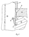
- the scraper plate 1, the mold ring 2 and the injection core 3 define the mold for the guarantee band 12.
- the injection core 3 also determines the inner shape of the closure cap 11.
- the mold cavity which defines the outer shape of the closure cap 11 has already been removed.
- the shaped ring 2 is drawn in the position in which it was lowered relative to the wiper plate 1 by the elastic force of the spring assembly 5, 6.
- the guarantee tape 12 was released in the lower part of its outer surface.
- the lowering of the mold ring 2 is made possible by the draft angle 10.
- the guarantee tape 12 is not drawn on the left side of the cap 11 in order to better recognize the details of the opened mold.
- the scraper plate 1 is provided with injection points 9 and therefore fulfills the function of a pouring crown during the injection process.
- the stripping plate 1 and the mold ring 2 are accommodated in a common plate which contains several of the devices shown in FIG. 1 at the same time.
- Several push rods 8 are provided for each device in order to raise the shaped ring 2 against the force of the spring assembly 5, 6 and thus to close the mold for the guarantee band 12.
- the scraper rods 7 serve to raise and lower the scraper plate 1.
- the stripping plate 1 is moved with the help of the stripping rods 7 into the position in which it acts as a pouring crown.
- the mold ring 2 closes the mold down with the aid of the push rods 8, while a mold cavity (not shown) is placed over the injection core 3 in order to close the mold for the actual closure cap 11 upwards.
- the spring assembly 5, 6 is compressed by lifting the form ring 2.
- the greater part of the cap 11 is poured from the top by central injection. Polyethylene is preferably used as the injection material.
- the remaining material for the lower part of the closure cap 11 and the material for the guarantee band 12 are injected.
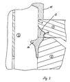
- FIG. 2 shows the sectional view of the pouring crown 1 at a point at which the guarantee band 12 is separated from the closure cap 11 by an intermediate space is.
- the spaces and the webs form the predetermined breaking line for later use.
- the predetermined breaking point can also consist of several predetermined breaking points distributed over the circumference of 360 ° with stronger intermediate webs.
- the material that is injected in points 9 flows all the way down to an annular recess 4 which is incorporated in the mold ring 2.
- the notch in the injection core 3, which is shown in FIG. 2 also forms the inner bead 14, which comes to rest under the bottle neck after a beverage bottle has been closed.
- no demoulding aid for the guarantee strip 12 is provided in this exemplary embodiment.
- the mold opens.
- the mold nest (not shown) is lifted off.
- the push rods 8 are released and the spring assembly 5, 6 presses the mold ring 2 down.
- the slight draft angle 10 of the form ring 2 allows increasingly larger free spaces to arise in the course of the lowering movement.
- the material of the guarantee band 12 is flexible and the radial extent of the recess 4 extends slightly beyond the upper edge of the shaped ring 2.
- the webs (not shown) and the underside of the bead 14 jointly exert the relatively small force that is necessary to pull the nose 13 out of the recess 4.
- the shape according to FIG. 2 can be adapted to the elastic properties of the polyethylene material used in such a way that the nose 13 is not sheared off or otherwise damaged when the shaped ring 2 is lowered.
- the nose 13 After the form ring 2 is opened up to the lower edge of the nose 13, the nose 13 jumps onto the upper edge of the form ring 2 and turns slightly outwards. Then the large plate, in which the stripping plate 1 and the mold ring 2 are housed together, runs upwards using the stripping rods 7. During this movement, the scraper plate 1 lifts the cap 11 upwards because it grasps the lower edge of the cap 11 between the webs. At the same time, the molding ring 2 presses against the edge 13 of the tamper-evident strip 12 which is turned outwards and brushes the bead 14 upwards over the injection core 3. In this way, the webs (not shown) are not loaded by any significant tensile forces.
- the top of the bead 14 may even be sunk in a V-shape. Nevertheless, the wiping movement can be carried out.
- Such a shape on the bead 14 was previously only possible if the guarantee strip 12 was produced separately from the closure cap 11 and was demolded downward by a reverse stripping movement.
- the second exemplary embodiment according to FIG. 3 provides an undercut 15 in the area of the scraper plate 1 instead of the nose 13 on the lower edge of the guarantee band 12.
- the stripping plate 1 engages under the guarantee strip 12 during the upward demolding movement. Otherwise, the lower part of the guarantee band 12 is also released here by the lowering of the form ring 2 before the stripping movement.
- the cylindrical outer surface of the injection core 3 is also fixed here during the entire demolding process, so that the stripping movement of the plate 1 takes effect immediately.
Landscapes
- Engineering & Computer Science (AREA)
- Mechanical Engineering (AREA)
- Manufacturing & Machinery (AREA)
- Closures For Containers (AREA)
- Moulds For Moulding Plastics Or The Like (AREA)
- Slide Fasteners, Snap Fasteners, And Hook Fasteners (AREA)
- Protection Of Pipes Against Damage, Friction, And Corrosion (AREA)
- Cleaning And De-Greasing Of Metallic Materials By Chemical Methods (AREA)
- Pressure Vessels And Lids Thereof (AREA)
- Finish Polishing, Edge Sharpening, And Grinding By Specific Grinding Devices (AREA)
Applications Claiming Priority (2)
| Application Number | Priority Date | Filing Date | Title |
|---|---|---|---|
| DE4016350A DE4016350A1 (de) | 1990-05-21 | 1990-05-21 | Verfahren und vorrichtung zur entformung eines garantiebands einer verschlusskappe |
| DE4016350 | 1990-05-21 |
Publications (3)
| Publication Number | Publication Date |
|---|---|
| EP0458250A2 true EP0458250A2 (fr) | 1991-11-27 |
| EP0458250A3 EP0458250A3 (en) | 1993-01-27 |
| EP0458250B1 EP0458250B1 (fr) | 1995-03-01 |
Family
ID=6406893
Family Applications (1)
| Application Number | Title | Priority Date | Filing Date |
|---|---|---|---|
| EP91108155A Expired - Lifetime EP0458250B1 (fr) | 1990-05-21 | 1991-05-21 | Procédé et dispositif de démoulage de la bande de garantie d'un capuchon de fermeture |
Country Status (6)
| Country | Link |
|---|---|
| US (1) | US5230856A (fr) |
| EP (1) | EP0458250B1 (fr) |
| AT (1) | ATE119100T1 (fr) |
| DE (1) | DE4016350A1 (fr) |
| ES (1) | ES2069117T3 (fr) |
| IT (1) | IT1241604B (fr) |
Cited By (5)
| Publication number | Priority date | Publication date | Assignee | Title |
|---|---|---|---|---|
| WO1994018085A1 (fr) * | 1993-02-09 | 1994-08-18 | Le Moulage Automatique | Dispositif de bouchage pour recipient |
| FR2706426A1 (fr) * | 1993-06-10 | 1994-12-23 | Moulage Automatique Sa | Dispositif de bouchage pour récipient. |
| EP0650444B2 (fr) † | 1992-07-16 | 2002-12-04 | Closures and Packaging Services Limited | Fermeture inviolable |
| US6991123B2 (en) | 1997-07-14 | 2006-01-31 | Closures And Packaging Services Limited | Closure with extended seal member |
| WO2008029234A1 (fr) * | 2006-08-31 | 2008-03-13 | Specialised Plastic Industries Cc | Couvercle plastique pour un récipient à partie supérieure ouverte |
Families Citing this family (18)
| Publication number | Priority date | Publication date | Assignee | Title |
|---|---|---|---|---|
| US5368469A (en) * | 1993-08-26 | 1994-11-29 | Phoenix Closures, Inc. | Apparatus for molding closures having tamper evident bands |
| US6113827A (en) | 1996-11-05 | 2000-09-05 | Styczynski; Robert J. | Method for molding and curing silicone |
| BR9904821A (pt) * | 1998-03-03 | 2000-08-29 | Frank Schellenbach | Tampa de fechamento plástica com banda de garantia anular destacável e vedação interna |
| US6099785A (en) * | 1998-03-17 | 2000-08-08 | Schweigert; Lothar | Method for injection molding plastic closures |
| US6506330B1 (en) | 1998-03-17 | 2003-01-14 | Lothar Schweigert | Apparatus and method for molding plastic closures |
| US6238202B1 (en) * | 1999-02-26 | 2001-05-29 | Unique Mould Makers Limited | Apparatus for ejecting threaded injection molded parts |
| US6279766B1 (en) | 1999-08-10 | 2001-08-28 | Rexam Medical Packaging Inc. | Safety closure with tamper-resistant locking tab and method and apparatus for making same |
| US6426030B1 (en) | 1999-11-15 | 2002-07-30 | Rexam Medical Packaging Inc. | Method of making a molded internally threaded closure |
| US6355201B1 (en) | 2000-09-07 | 2002-03-12 | Captive Plastics, Inc. | Tamper-indicating closure with resilient locking projections |
| US6331028B1 (en) | 2000-10-17 | 2001-12-18 | Advance Usa, Inc. | Fiber-reinforced composite structure |
| US6405886B1 (en) | 2001-02-08 | 2002-06-18 | Rexam Medical Packaging Inc. | Closure having a tamper indicating band |
| US20070053812A1 (en) * | 2003-03-07 | 2007-03-08 | Tosoh Corporation | Minute flow path structure body and die |
| DE102009044643A1 (de) | 2009-11-24 | 2011-05-26 | Kunststofftechnik Waidhofen An Der Thaya Gmbh | Verschlusskappe mit Garantiering sowie Spritzgießwerkzeug und Verfahren zu deren Herstellung |
| WO2013029167A1 (fr) * | 2011-08-30 | 2013-03-07 | Husky Injection Molding Systems Ltd. | Manchon décrocheur |
| CN103737868B (zh) * | 2013-12-31 | 2016-05-11 | 南烽精密机械(深圳)有限公司 | 一种塑料瓶盖模具的脱模机构及其实现方法 |
| WO2018064750A1 (fr) * | 2016-10-05 | 2018-04-12 | Husky Injection Molding Systems Ltd. | Appareil de moulage et procédé de commande dudit appareil de moulage |
| CN111673983A (zh) * | 2020-05-17 | 2020-09-18 | 宁波正佳模塑有限公司 | 一种错齿卡环塑件的成型模具结构 |
| CN112606302B (zh) * | 2020-12-05 | 2023-01-06 | 安吉晟汇氟塑科技有限公司 | 一种聚四氟乙烯碟板无损脱模装置 |
Family Cites Families (24)
| Publication number | Priority date | Publication date | Assignee | Title |
|---|---|---|---|---|
| DE1859147U (de) * | 1962-05-26 | 1962-09-27 | Hans Rohrbeck | Verschluss aus plastischen kunststoffen fuer flaschen, roehrchen, dosen u. dgl. mit einem halswulstring. |
| US3344942A (en) * | 1966-04-05 | 1967-10-03 | Hedgewick Peter | Safety cap and container |
| US3584111A (en) * | 1968-10-03 | 1971-06-08 | Owens Illinois Inc | Method and apparatus for molding plastic articles |
| CH598931A5 (fr) * | 1975-08-27 | 1978-05-12 | Poloplast Kunststoffwerk | |
| IT1166774B (it) * | 1978-05-26 | 1987-05-06 | Plastivit Sa | Tappo di materiale plastico ed attrezzo per la sua formatura per iniezione |
| FR2457813A1 (fr) * | 1979-05-31 | 1980-12-26 | Grussen Jean | Capsule a vis en matiere plastique pour bouteilles |
| US4496302A (en) * | 1982-06-04 | 1985-01-29 | Husky Injection Molding Systems Inc. | Apparatus for molding plastic articles |
| US4555039A (en) * | 1982-07-13 | 1985-11-26 | American Safety Closure Corp. | Pilfer-proof cap |
| US4526282A (en) * | 1983-05-05 | 1985-07-02 | Sun Coast Plastics, Inc. | Tamper proof closure cap, method, and tool for making same |
| US4552328A (en) * | 1984-01-05 | 1985-11-12 | Sun Coast Plastics, Inc. | Mold for making tamper-proof closure |
| AR245671A1 (es) * | 1984-08-15 | 1994-02-28 | American Safety Closure | Perfeccionamientos en tapones de material plastico a prueba de manipulaciones indebidas. |
| US4806301A (en) * | 1984-08-15 | 1989-02-21 | American Safety Closure Corp. | Process of removing a plastic cap from a mold |
| CH664131A5 (de) * | 1984-10-09 | 1988-02-15 | Wiedmer Plastikform W | Aus kunststoff bestehender verschluss fuer behaelter mit garantiering. |
| US4570897A (en) * | 1985-01-23 | 1986-02-18 | Holdt J W Von | Mold for container with recess-defining flange |
| US4648834A (en) * | 1985-06-07 | 1987-03-10 | Holdt J W Von | Mold for manufacturing flanged objects without side action |
| US4983346A (en) * | 1985-11-12 | 1991-01-08 | Mt. Vernon Plastics Corporation | Method for molding a one-piece molded end closure |
| CH669556A5 (en) * | 1986-01-16 | 1989-03-31 | Obrist Ag Crown | Injection moulds for screw closure caps |
| US4741447A (en) * | 1987-04-27 | 1988-05-03 | American National Can Company | Linerless cap closure |
| FR2619552B1 (fr) * | 1987-08-18 | 1990-02-02 | Astra Plastique | Bouchon a vis a ceinture d'inviolabilite, du type demoule par devissage, et moule utilise pour la fabrication de ce bouchon |
| US4751036A (en) * | 1987-09-14 | 1988-06-14 | Owens-Illinois Closure Inc. | Method for producing a closure with a tamper indicating band |
| JPH01104832A (ja) * | 1987-10-12 | 1989-04-21 | Toray Ind Inc | ポリエステル2成分複合糸 |
| US4933133A (en) * | 1988-05-11 | 1990-06-12 | Brown Edward M | Container closure and method for manufacture thereof |
| US4881892A (en) * | 1988-10-11 | 1989-11-21 | American National Can Company | Apparatus for making tamper-evident closures |
| US5053182A (en) * | 1989-09-05 | 1991-10-01 | Caran Engineering Investments, Inc. | One piece safety cap molding apparatus and method |
-
1990
- 1990-05-21 DE DE4016350A patent/DE4016350A1/de active Granted
- 1990-12-18 IT IT68016A patent/IT1241604B/it active IP Right Grant
-
1991
- 1991-05-21 EP EP91108155A patent/EP0458250B1/fr not_active Expired - Lifetime
- 1991-05-21 ES ES91108155T patent/ES2069117T3/es not_active Expired - Lifetime
- 1991-05-21 US US07/703,385 patent/US5230856A/en not_active Expired - Fee Related
- 1991-05-21 AT AT91108155T patent/ATE119100T1/de not_active IP Right Cessation
Cited By (6)
| Publication number | Priority date | Publication date | Assignee | Title |
|---|---|---|---|---|
| EP0650444B2 (fr) † | 1992-07-16 | 2002-12-04 | Closures and Packaging Services Limited | Fermeture inviolable |
| WO1994018085A1 (fr) * | 1993-02-09 | 1994-08-18 | Le Moulage Automatique | Dispositif de bouchage pour recipient |
| AU696551B2 (en) * | 1993-02-09 | 1998-09-10 | Le Moulage Automatique Societe Anonyme | Container closure device |
| FR2706426A1 (fr) * | 1993-06-10 | 1994-12-23 | Moulage Automatique Sa | Dispositif de bouchage pour récipient. |
| US6991123B2 (en) | 1997-07-14 | 2006-01-31 | Closures And Packaging Services Limited | Closure with extended seal member |
| WO2008029234A1 (fr) * | 2006-08-31 | 2008-03-13 | Specialised Plastic Industries Cc | Couvercle plastique pour un récipient à partie supérieure ouverte |
Also Published As
| Publication number | Publication date |
|---|---|
| IT9068016A1 (it) | 1991-11-22 |
| DE4016350A1 (de) | 1991-11-28 |
| IT1241604B (it) | 1994-01-19 |
| ES2069117T3 (es) | 1995-05-01 |
| IT9068016A0 (it) | 1990-12-18 |
| EP0458250A3 (en) | 1993-01-27 |
| EP0458250B1 (fr) | 1995-03-01 |
| DE4016350C2 (fr) | 1992-10-08 |
| US5230856A (en) | 1993-07-27 |
| ATE119100T1 (de) | 1995-03-15 |
Similar Documents
| Publication | Publication Date | Title |
|---|---|---|
| EP0458250B1 (fr) | Procédé et dispositif de démoulage de la bande de garantie d'un capuchon de fermeture | |
| EP2097329B1 (fr) | Semi-produit pour fabriquer un dispositif d'ouverture | |
| DE69712954T2 (de) | Zum Zeitpunkt der Entsorgung von einer Flasche trennbare Scharnierkappe | |
| DE69502134T2 (de) | Verbesserung des Verfahrens zum Herstellen einer Verschlussvorrichtung und Maschine dafür | |
| DE60310771T2 (de) | Verschlussstopfen für einen kanister sowie verfahren zur dessen herstellung | |
| DE69705929T2 (de) | Form zur herstellung von verschlusskappen mit umgebogenen laschen sowie eine in einer solchen form hergestellte verschlusskappe | |
| DE2026964C2 (de) | Vorrichtung zum Formen, Füllen und Verschließen von Kunststoffbehältern | |
| DE69228553T2 (de) | Vorrichtung und verfahren zum herstellen eines spritzgegossenen rahmens mit einem platteneinsatz | |
| EP0329640B1 (fr) | Fermeture inviolable pour un récipient et moule à injection pour la fabrication de la fermeture | |
| DE2842293A1 (de) | Behaelter mit deckel aus kunststoffmaterial | |
| DE3231859C2 (de) | In einem Arbeitsgang hergestellter, gefüllter und verschlossener, blasgeformter, flaschenförmiger Behälter | |
| EP0282763A2 (fr) | Manchon fileté en plastique | |
| EP0951428B1 (fr) | Bouchon filete en plastique pour bouteilles, muni d'une bande d'inviolabilite | |
| EP0312725A2 (fr) | Bouteile compte-gouttes et procédé pour sa fabrication | |
| WO1984002694A1 (fr) | Couvercle de recipient et installation pour sa fabrication | |
| WO1989007516A1 (fr) | Procede et dispositif pour fabriquer des pieces moulees en materiau thermoplastique | |
| EP0073356A1 (fr) | Procédé pour la production d'un tube d'une matière synthétique avec un bonnet de fermeture appartenant au tube | |
| DE60105553T2 (de) | Verfahren und vorrichtung zum verformen eines verschlussstopfens für sektflaschen | |
| DE1942312C3 (de) | Durch axiales Aufpressen auf den Hals einer Flasche aufbringbare Verschlußkappe | |
| DE3881687T2 (de) | Form zur herstellung einer vom gehaeuse abschraubbaren originalitaetsverschlusskappe. | |
| EP1004123B1 (fr) | Procede et moule pour fabriquer des isolateurs type parapluie | |
| EP0260628A1 (fr) | Moule de vulcanisation de pneumatiques | |
| DE3439212A1 (de) | Schraubverschluss mit originalitaetssicherung aus kunststoff und spritzgiesswerkzeug zur herstellung von kappen | |
| DE2819170C2 (fr) | ||
| DE2048596A1 (de) | Verfahren und Vorrichtung zuti Anformen von Gummi an einen vorgefertigten Artikel |
Legal Events
| Date | Code | Title | Description |
|---|---|---|---|
| PUAI | Public reference made under article 153(3) epc to a published international application that has entered the european phase |
Free format text: ORIGINAL CODE: 0009012 |
|
| AK | Designated contracting states |
Kind code of ref document: A2 Designated state(s): AT BE CH ES FR GB LI NL |
|
| PUAL | Search report despatched |
Free format text: ORIGINAL CODE: 0009013 |
|
| AK | Designated contracting states |
Kind code of ref document: A3 Designated state(s): AT BE CH ES FR GB LI NL |
|
| 17P | Request for examination filed |
Effective date: 19930125 |
|
| 17Q | First examination report despatched |
Effective date: 19930902 |
|
| GRAA | (expected) grant |
Free format text: ORIGINAL CODE: 0009210 |
|
| AK | Designated contracting states |
Kind code of ref document: B1 Designated state(s): AT BE CH ES FR GB LI NL |
|
| REF | Corresponds to: |
Ref document number: 119100 Country of ref document: AT Date of ref document: 19950315 Kind code of ref document: T |
|
| ET | Fr: translation filed | ||
| REG | Reference to a national code |
Ref country code: ES Ref legal event code: FG2A Ref document number: 2069117 Country of ref document: ES Kind code of ref document: T3 |
|
| GBT | Gb: translation of ep patent filed (gb section 77(6)(a)/1977) |
Effective date: 19950612 |
|
| PLBE | No opposition filed within time limit |
Free format text: ORIGINAL CODE: 0009261 |
|
| STAA | Information on the status of an ep patent application or granted ep patent |
Free format text: STATUS: NO OPPOSITION FILED WITHIN TIME LIMIT |
|
| 26N | No opposition filed | ||
| PGFP | Annual fee paid to national office [announced via postgrant information from national office to epo] |
Ref country code: FR Payment date: 19960524 Year of fee payment: 6 |
|
| PGFP | Annual fee paid to national office [announced via postgrant information from national office to epo] |
Ref country code: GB Payment date: 19960529 Year of fee payment: 6 |
|
| PGFP | Annual fee paid to national office [announced via postgrant information from national office to epo] |
Ref country code: NL Payment date: 19960530 Year of fee payment: 6 Ref country code: ES Payment date: 19960530 Year of fee payment: 6 |
|
| PGFP | Annual fee paid to national office [announced via postgrant information from national office to epo] |
Ref country code: AT Payment date: 19960531 Year of fee payment: 6 |
|
| PGFP | Annual fee paid to national office [announced via postgrant information from national office to epo] |
Ref country code: CH Payment date: 19960604 Year of fee payment: 6 |
|
| PGFP | Annual fee paid to national office [announced via postgrant information from national office to epo] |
Ref country code: BE Payment date: 19960612 Year of fee payment: 6 |
|
| PG25 | Lapsed in a contracting state [announced via postgrant information from national office to epo] |
Ref country code: GB Effective date: 19970521 Ref country code: AT Effective date: 19970521 |
|
| PG25 | Lapsed in a contracting state [announced via postgrant information from national office to epo] |
Ref country code: ES Free format text: LAPSE BECAUSE OF NON-PAYMENT OF DUE FEES Effective date: 19970522 |
|
| PG25 | Lapsed in a contracting state [announced via postgrant information from national office to epo] |
Ref country code: LI Free format text: LAPSE BECAUSE OF NON-PAYMENT OF DUE FEES Effective date: 19970531 Ref country code: CH Free format text: LAPSE BECAUSE OF NON-PAYMENT OF DUE FEES Effective date: 19970531 Ref country code: BE Effective date: 19970531 |
|
| BERE | Be: lapsed |
Owner name: SCHELLENBACH FRANK Effective date: 19970531 |
|
| PG25 | Lapsed in a contracting state [announced via postgrant information from national office to epo] |
Ref country code: NL Effective date: 19971201 |
|
| GBPC | Gb: european patent ceased through non-payment of renewal fee |
Effective date: 19970521 |
|
| REG | Reference to a national code |
Ref country code: CH Ref legal event code: PL |
|
| PG25 | Lapsed in a contracting state [announced via postgrant information from national office to epo] |
Ref country code: FR Free format text: LAPSE BECAUSE OF NON-PAYMENT OF DUE FEES Effective date: 19980130 |
|
| NLV4 | Nl: lapsed or anulled due to non-payment of the annual fee |
Effective date: 19971201 |
|
| REG | Reference to a national code |
Ref country code: FR Ref legal event code: ST |
|
| REG | Reference to a national code |
Ref country code: ES Ref legal event code: FD2A Effective date: 19990405 |