EP0458341A1 - Zylinderkopf eines Doppelnockenwellenmotors - Google Patents
Zylinderkopf eines Doppelnockenwellenmotors Download PDFInfo
- Publication number
- EP0458341A1 EP0458341A1 EP91108376A EP91108376A EP0458341A1 EP 0458341 A1 EP0458341 A1 EP 0458341A1 EP 91108376 A EP91108376 A EP 91108376A EP 91108376 A EP91108376 A EP 91108376A EP 0458341 A1 EP0458341 A1 EP 0458341A1
- Authority
- EP
- European Patent Office
- Prior art keywords
- cylinder head
- intake
- camshaft
- exhaust
- cover
- Prior art date
- Legal status (The legal status is an assumption and is not a legal conclusion. Google has not performed a legal analysis and makes no representation as to the accuracy of the status listed.)
- Ceased
Links
Images



Classifications
-
- F—MECHANICAL ENGINEERING; LIGHTING; HEATING; WEAPONS; BLASTING
- F01—MACHINES OR ENGINES IN GENERAL; ENGINE PLANTS IN GENERAL; STEAM ENGINES
- F01L—CYCLICALLY OPERATING VALVES FOR MACHINES OR ENGINES
- F01L1/00—Valve-gear or valve arrangements, e.g. lift-valve gear
- F01L1/02—Valve drive
-
- F—MECHANICAL ENGINEERING; LIGHTING; HEATING; WEAPONS; BLASTING
- F01—MACHINES OR ENGINES IN GENERAL; ENGINE PLANTS IN GENERAL; STEAM ENGINES
- F01L—CYCLICALLY OPERATING VALVES FOR MACHINES OR ENGINES
- F01L1/00—Valve-gear or valve arrangements, e.g. lift-valve gear
- F01L1/02—Valve drive
- F01L1/024—Belt drive
-
- F—MECHANICAL ENGINEERING; LIGHTING; HEATING; WEAPONS; BLASTING
- F01—MACHINES OR ENGINES IN GENERAL; ENGINE PLANTS IN GENERAL; STEAM ENGINES
- F01L—CYCLICALLY OPERATING VALVES FOR MACHINES OR ENGINES
- F01L1/00—Valve-gear or valve arrangements, e.g. lift-valve gear
- F01L1/02—Valve drive
- F01L1/026—Gear drive
-
- F—MECHANICAL ENGINEERING; LIGHTING; HEATING; WEAPONS; BLASTING
- F01—MACHINES OR ENGINES IN GENERAL; ENGINE PLANTS IN GENERAL; STEAM ENGINES
- F01L—CYCLICALLY OPERATING VALVES FOR MACHINES OR ENGINES
- F01L1/00—Valve-gear or valve arrangements, e.g. lift-valve gear
- F01L1/02—Valve drive
- F01L1/04—Valve drive by means of cams, camshafts, cam discs, eccentrics or the like
- F01L1/047—Camshafts
- F01L1/053—Camshafts overhead type
-
- F—MECHANICAL ENGINEERING; LIGHTING; HEATING; WEAPONS; BLASTING
- F01—MACHINES OR ENGINES IN GENERAL; ENGINE PLANTS IN GENERAL; STEAM ENGINES
- F01M—LUBRICATING OF MACHINES OR ENGINES IN GENERAL; LUBRICATING INTERNAL COMBUSTION ENGINES; CRANKCASE VENTILATING
- F01M13/00—Crankcase ventilating or breathing
- F01M13/04—Crankcase ventilating or breathing having means for purifying air before leaving crankcase, e.g. removing oil
-
- F—MECHANICAL ENGINEERING; LIGHTING; HEATING; WEAPONS; BLASTING
- F02—COMBUSTION ENGINES; HOT-GAS OR COMBUSTION-PRODUCT ENGINE PLANTS
- F02F—CYLINDERS, PISTONS OR CASINGS, FOR COMBUSTION ENGINES; ARRANGEMENTS OF SEALINGS IN COMBUSTION ENGINES
- F02F1/00—Cylinders; Cylinder heads
- F02F1/24—Cylinder heads
- F02F1/42—Shape or arrangement of intake or exhaust channels in cylinder heads
- F02F1/4214—Shape or arrangement of intake or exhaust channels in cylinder heads specially adapted for four or more valves per cylinder
-
- F—MECHANICAL ENGINEERING; LIGHTING; HEATING; WEAPONS; BLASTING
- F01—MACHINES OR ENGINES IN GENERAL; ENGINE PLANTS IN GENERAL; STEAM ENGINES
- F01L—CYCLICALLY OPERATING VALVES FOR MACHINES OR ENGINES
- F01L1/00—Valve-gear or valve arrangements, e.g. lift-valve gear
- F01L1/02—Valve drive
- F01L1/04—Valve drive by means of cams, camshafts, cam discs, eccentrics or the like
- F01L1/047—Camshafts
- F01L1/053—Camshafts overhead type
- F01L2001/0537—Double overhead camshafts [DOHC]
-
- F—MECHANICAL ENGINEERING; LIGHTING; HEATING; WEAPONS; BLASTING
- F02—COMBUSTION ENGINES; HOT-GAS OR COMBUSTION-PRODUCT ENGINE PLANTS
- F02B—INTERNAL-COMBUSTION PISTON ENGINES; COMBUSTION ENGINES IN GENERAL
- F02B2275/00—Other engines, components or details, not provided for in other groups of this subclass
- F02B2275/18—DOHC [Double overhead camshaft]
-
- F—MECHANICAL ENGINEERING; LIGHTING; HEATING; WEAPONS; BLASTING
- F02—COMBUSTION ENGINES; HOT-GAS OR COMBUSTION-PRODUCT ENGINE PLANTS
- F02F—CYLINDERS, PISTONS OR CASINGS, FOR COMBUSTION ENGINES; ARRANGEMENTS OF SEALINGS IN COMBUSTION ENGINES
- F02F7/00—Casings, e.g. crankcases
- F02F7/006—Camshaft or pushrod housings
Definitions
- the present invention relates to a cylinder head structure of a double overhead camshaft engine.
- a double overhead camshaft engine (which is herein referred to as a DOHC engine) is provided with a pair of overhead camshafts for a raw of cylinders, such as an intake camshaft and an exhaust camshaft, which are arranged in parallel with respect to a crankshaft of the engine.
- a drive camshaft is connected or coupled to the crankshaft by a belt which transmits the engine output to drive the drive camshaft.
- the other, called driven camshaft is connected or coupled to the drive camshaft by transmission means, such as in-mesh camshaft gears secured to the drive and driven camshafts, respectively, which transmits the rotation of the drive camshaft to drive the driven camshaft.
- a valve drive mechanism or valve train is provided so as to drive one valve by one cam robe.
- a valve train is known from, for instance, Japanese Unexamined Utility Model Publication No. 61 - 171,807.
- Each valve drive mechanism cooperates with a hydraulic valve lash adjuster which supports and urges a rocker arm disposed between a cam robe of the overhead camshaft and a valve stem so as to maintain zero valve stem to rocker clearance.
- a hydraulic valve lash adjuster is described in, for example, Japanese Unexamined Utility Model Publication No. 55 - 144803.
- Camshaft supporting means of this kind comprises two parts of bearing means for supporting for rotation the camshafts therebetween, such as cam carrier means, which are prepared separately from the cylinder head and bolted, or otherwise secured, to the cylinder head, and cap means formed integrally with a cylinder head cover.
- the DOHC engine of this kind can be reduced in width and, on the other hand, the camshaft supporting means can be constituted from a reduced number of parts and consequently allows to provide the DOHC engine simple in structure.
- DOHC engine In recent years, a DOHC engine is typically provided with a plurality of intake valves and a plurality of exhaust valves for one cylinder in order to increase intake charging efficiency so as to develop an increase in output power.
- Some DOHC engines of this kind have a plurality of intake and exhaust valves different in number for one cylinder.
- a cylinder head must be formed with a plurality of bores and holes for installing the valves and valve trains including the hydraulic valve lash adjusters and unavoidably causes a decrease in structural rigidity of the small-sized DOHC engine body.
- Oil which lubricates camshafts and the valves and operates the hydraulic valve lash adjusters, scatters over a cylinder head during engine operation and produces oil mist.
- quantity of oil mist on the cylinder head increases.
- blow-bye gas which is introduced into an oil separator, contains an increased quantity of oil mist, so that a large capacity of oil separator is necessary in order to process the blow-bye gas efficiently.
- the large capacity of oil separator occupies a large space even though making the DOHC engine small in size.
- In-mesh camshaft gears for operationally coupling the drive and driven camshafts is covered by a gear cover so as to permit neither foreign articles to be caught between the camshaft gears nor lubrication oil to scatter from the camshaft gears.
- the gear cover if secured to the DOHC engine with the cam carrier means, is secured to the cam carrier means for rigid connection.
- the gear cover is prepared as two parts separable in a direction parallel to the axis of the crankshaft.
- the gear cover comprises a front cover section and a rear cover section formed integrally with the cam carrier means and are bolted at several points around the peripheries of the camshaft gear, or otherwise secured, to each other so as to enclose marginal portions of the camshaft gears.
- the cam carrier means is constituted by radial bearing means and thrust bearing means. Since the camshaft gear has a diameter larger than diameters of the related camshaft and cam robes, the camshaft gear projects downward on a side of the cylinder head.
- the cylinder head is formed in an upper end portion with a recess for receiving lower parts of the in-mesh camshaft gears. That is, the in-mesh camshaft gears is accommodated in a space defined between the gear cover and the end recess.
- the cover members are weak in rigidity.
- the cover member since opening downward, the cover members are weak in rigidity.
- the cover member since the cover member is integrally provided with the camshaft supporting means, it receives external load from the camshafts, so as to be apt to cause a large, three dimensional deformation owing to a change of torque of the camshafts, abnormal operations of the valve means, such as jumping and bouncing, an angle of torsion of the camshaft, etc.
- the present invention has a primary object to provide a cylinder head structure for a double overhead camshaft engine provided with a plurality of intake valve and a plurality of exhaust valve for one cylinder which has a high structural rigidity.
- the present invention has another object to provide a cylinder head structure for a double overhead camshaft engine provided with a plurality of intake valve and a plurality of exhaust valve for one cylinder whose bearing means is free from deformation and seizing.
- the cylinder head structure for a double overhead camshaft engine provided with a plurality of intake valve and a plurality of exhaust valve for one cylinder includes a cylinder head block and a cylinder head cover mounted on the cylinder head block so as to support for rotation the intake and exhaust camshafts on the cylinder head block.
- the cylinder head block and cylinder head cover form therebetween a hermetically sealed chamber as an oil jacket.
- the cylinder head block is integrally formed with partition means, such as a lengthwise extending wall, for dividing the hermetically sealed chamber into two chambers enclosing major portions of the intake and exhaust camshafts, respectively, the chambers being in communication with each other near one ends of the chambers.
- Outlet means such as a hole, is formed in the cylinder head cover so as to permit blow-bye gas to flow out the chamber enclosing either one of the intake and exhaust camshafts which drives one of the intake and exhaust valves whose number for one cylinder is smaller than the number of the other valves.
- the outlet means is desirably located closer to another end of the chamber than to a position in which the chambers are in communication with each other.
- Cover means is bolted or otherwise secured to one end of camshaft carrier means formed as the cylinder head cover at a plurality of points around a gear train, such as comprising a pair of gears in mesh with each other, coupled to one ends of the intake and exhaust camshafts so as to turn the intake and exhaust camshafts in opposite directions.
- the cover means has bearing means integrally formed inside thereof so as to support the intake and exhaust camshafts, thereby restricting a movement of end portions of the intake and exhaust camshafts.
- the cover means further has reinforcing means, such as comprising a plurality of bosses for receiving bolts for fixing the cover means to the cylinder head, integrally formed outside thereof and extending along almost the whole vertical length of the cover means for providing an increase in rigidity of the cover means.
- the cylinder head is integrally formed with a boss which extends below the bearing means along the whole width of the cylinder head block and is formed with an oil passage.
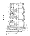
- a cylinder head 1 in accordance with a preferred embodiment of the present invention is shown, which is mounted on each one of left and right cylinder blocks (only one of which is shown), arranged in a V-formation with a predetermined relative angle, for example, a relative angle of 60 degrees, of an overhead camshaft (DOHC) engine A, such as a V-6 DOHC engine, of the type having three intake ports and two exhaust ports for one cylinder (not shown).
- DOHC overhead camshaft
- the cylinder head 1 is formed with various bores, such as three intake valve guide bores 5, two exhaust valve guide bores 6, one plug installation bore 7, three hydraulic valve lash adjuster installation bores 8a and two hydraulic valve lash adjuster installation bores 8b for each cylinder.
- Camshaft carrier means 2 constructed to serve as cylinder head cover and cam cap, is mounted on the cylinder head 1.
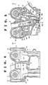
- intake and exhaust overhead camshafts 3 and 4 are disposed so as to drive intake valves 18 and exhaust valves 19 (see Figure 5).
- the camshaft carrier means 2 is integrally formed with bearing means. That is, the camshaft carrier means 2 is integrally formed with bosses 9 in alignment with the plug installation bores 7, respectively, which are in a row parallel to the row of the cylinders and extend upward from the upper surface thereof.
- the camshaft carrier means 2 is further integrally formed with a plurality of journal bearings 10 and 11, which are arranged in rows on opposite sides of the row of the bosses 9 inside the camshaft carrier means 2, so as to support for rotation the intake and exhaust overhead camshafts 3 and 4, respectively.
- the intake camshaft 3 is formed with a cam robe for one intake valve 18 and is provided with a camshaft gear 12 secured to one end of the intake camshaft 3.
- the exhaust camshaft 4 is formed with a cam robe for one exhaust valve 19 and is provided with a camshaft gear 13 secured to one end of the exhaust camshaft 4.
- These camshaft gears 12 and 13 are in mesh with each other in a gear chamber 27 formed at one end of the cylinder head 1.
- Either one of the camshafts 3 and 4 projects outside of the cylinder head 1 is provided with a camshaft pulley (not shown) which is connected or coupled by a belt (not shown) to a crankshaft (not shown) of the engine A so as to transmit the engine output to the camshaft 3 or 4, thereby driving the camshafts 3 and 4 in opposite directions.
- the cylinder head 1 is provided with a combustion chamber 15 formed in each cylinder at a lower part of the cylinder head 1.
- the combustion chamber 7 is provided with three intake ports 16 for one cylinder whose openings extend to one side of the cylinder head 1. Further, the combustion chamber 7 is provided with two exhaust ports 17 for one cylinder whose openings extend to the opposite side of the cylinder head 1 remote from the intake ports 16.
- Each intake port 16, opening into the combustion chamber 15, is opened and shut at a predetermined timing by intake valve means 18.
- Each exhaust ports 17, opening into the combustion chamber 15, is opened and shut at a predetermined timing by exhaust valve means 19.
- Fuel mixture is introduced into the cylinder through the intake ports 16 while opened by the intake valve means 18, respectively. Then, after squeezing, or compressing, the fuel mixture in the cylinder, a spark plug 26 provides a spark inside the combustion chamber 15 so that the fuel mixture explodes. Thereafter, burned gases are blown out of the cylinder through the exhaust ports 17 while opened by the exhaust valve means 19.
- Intake valve means 18, comprising a valve stem 18a and an intake valve 18b formed integrally with the intake valve stem 18a, is driven by a valve train.
- the valve train comprises a valve spring 21 for urging the intake valve 18b in a direction wherein the intake valve 18b opens the intake port 16, an intake valve guide sleeve 5a in the guide bore 5 for supporting the valve stem 14 for sliding movement, a rocker arm 23 with a roller 25 which is operated by an intake camshaft lobe 3a rubbing on the roller 25 of the rocker arm 23 and a hydraulic valve lash adjuster 22.
- the hydraulic valve lash adjuster 22 which may take any known type, is provided with a pivot 24 brought into contact with one end of the rocker arm 23 by hydraulic oil delivered through an oil passage 36 formed in the cylinder head 1 so as to maintain zero valve stem to rocker clearance.
- the intake valve means 1 is provided with a valve spring retainer 20 secured to an upper end portion of the valve stem 18a.
- the exhaust valve means 19, comprising a valve stem 19a and an intake valve 19b formed integrally with the intake valve stem 19a, is driven by a valve train which is the same in structure as the valve train of the intake valve.
- the intake valve means 18 for each cylinder are located at points or vertices of a triangle so that two of the three intake valve means 18 are in a straight line extending in a lengthwise direction of the engine body A.
- the three hydraulic lash valve adjusters 22 of the intake valve means 18 for each cylinder are arranged in a triangular pattern surrounding the center intake valve means 18.
- the exhaust valve means 19 are arranged in a row in a lengthwise direction of the engine body A and the hydraulic lash valve adjusters 22 of the exhaust valve means 19 for the cylinders are arranged in a row parallel with the row of the exhaust valve means 19.
- the difference in number between the intake and exhaust valve means 18 and 19 for one cylinder provides an available space between each adjacent cylinders smaller on a side of the intake valve means 18 than on a side of the exhaust valve means 19 and accordingly, a distance between each adjacent journal bearings 10 for the intake camshaft 3 is smaller than a distance between each adjacent journal bearings 11 for the exhaust camshaft 4.
- the cylinder head 1 is integrally formed with an elongated partition wall 28 between the row of the intake valve guide bores 5 and the row of the plug installation bores 7.
- the partition wall 28 is located in the transverse direction of the cylinder head 1 closer to the row of the intake valve guide bores 5 than to the row of the exhaust valve guide bores 6 and extends in the lengthwise direction of the cylinder head 1 from the gear chamber 27 to the rear end of the peripheral connecting wall 29.
- the camshaft carrier means 2 is integrally formed with an elongated partition wall 30 extending vertically downward which abuts against an upper surface of the partition wall 28 of the cylinder head 1.
- the oil jacket P defined between the cylinder head 1 and camshaft carrier means 2 is divided into two oil chambers 31 and 32 by means of the elongated partition walls 28 and 30 abutting against each other. Since the elongated partition wall 28 of the cylinder head 1 does not extend inside the gear chamber 27, the two oil chamber 31 and 32 communicate with each other through the gear chamber 27 as is shown by an arrow X in Figure 2. In other words, the oil jacket P is formed as a U-shaped space between the cylinder head 1 and camshaft carrier means 2.
- the camshaft carrier means 2 is formed with a rib 33 forming a space S therein to which an oil separator 34 is bolted.
- a plurality of buffer ribs 34a are formed in the space S so as to provide a zigzag path for blow-bye gas.
- Blow-bye gas is introduced into the oil separator 34 from the oil jacket P through a blow-bye gas inlet 35 formed in the camshaft carrier means 2. It is desired to locate the blow-bye gas inlet 35 so as to open into the oil chamber 32 under the exhaust camshaft 4 that has a less number of valves than the intake camshaft 3 and to be far away from the gear chamber 27 of the cylinder head 1 in the lengthwise direction.
- First to third oil passages 36, 37 and 38 for supplying oil to the hydraulic valve lash adjusters 22 are formed in the elongated partition wall 28 and side ribs 1a of the cylinder head 1, respectively.
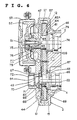
- the intake camshaft 3 extends in a lengthwise direction of the cylinder head 1 (from the right or front to the left or rear in Figure 6) so as to be in parallel with the crankshaft of the engine A , and is supported for rotation by a radial bearing portions 46 formed integrally with the camshaft carrier means 2 and a radial bearing portion 47 formed integrally with the camshaft cover means 44.
- the exhaust camshaft 4 extends in the lengthwise direction so as to be in parallel with the crankshaft and hence, the intake camshaft 3, and is supported for rotation by a radial bearing portion 48 formed integrally with the camshaft carrier means 2 and a radial bearing portion 49 formed integrally with the camshaft cover means 44.
- Front end of the intake camshaft 3 is provided with a timing pulley 52 secured thereto by a bolts 51.
- This pulley 52 is connected or coupled to the crankshaft by a belt (not shown) which transmits the engine output to drive the pulley 52 at a speed of one-half of the crankshaft.
- the pulley 52 is protected by a pulley cover 53.
- the intake camshaft gear 12 of the intake camshaft 3 located slightly rearward of the pulley 52 and the exhaust camshaft gear 13 provided near the front end of the exhaust camshaft 4 are in mesh with each other so as to rotate at the same speed but in the opposite directions.
- a gear 61 is provided so as to mesh with the intake camshaft gear 12 and to be able to displace with respect to the exhaust camshaft gear 13.
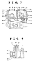
- These camshaft gears 12 and 13 are enclosed within the gear chamber 27 defined between the cylinder head 1 and camshaft carrier means 2, and, particularly, by the camshaft cover means 44, a gear casing portion 57 formed as a front end portion of the camshaft carrier means 2 and a groove 58 (see Figure 7) formed in a front upper portion of the cylinder head 1.
- the intake camshaft 3 has a front journal 62A which supports the intake camshaft gear 12 in the gear chamber 27 having a diameter larger than that of the front end portion of the intake camshaft 3 so that a front surface of the front journal 62A slidably abuts against a rear thrust surface 63 of the boss of the camshaft cover means 44 which serves as a part of a thrust bearing means.
- the intake camshaft 3 is provided behind the front journal 62A of the intake camshaft 3 with a thrust collar 64 having a diameter larger than that of the front journal 62A of the intake camshaft 3.
- the thrust collar 64 slidably abuts against a front thrust surface 65 of the boss of the camshaft carrier means 2 which serves as another part of the thrust bearing means.
- the thrust bearing means comprising the front and rear thrust surfaces 63 and 65 supports the intake camshaft 2 so as to prevent a thrust movement of the intake camshaft 2.
- the intake camshaft 2 is further formed behind the thrust collar 64 with a rear journal 62B having a diameter between those of the front journal 62A and the thrust collar 64.
- a peripheral surface of the rear journal 62B is board by an inner surface of a bore 46, serving as radial bearing means, formed in the boss of the camshaft carrier means 2.
- Exhaust camshaft 4 is provided with a lock nut 66 secured thereto behind the exhaust camshaft gear 13.
- the lock nut 66 slidably abuts against a rear thrust surface of a front thrust metal 67 embedded in the camshaft cover means 44 which serves as a part of thrust bearing means.
- the exhaust camshaft 4 is further provided behind the exhaust camshaft gear 13 with a thrust collar 68 slidably abutting against a front thrust surface 69 of the boss of the camshaft carrier means 2 which serves as another part of the thrust bearing means.
- the thrust bearing means comprising the front thrust metal 67 and the thrust collar 68 supports the exhaust camshaft 4 so as to prevent a thrust movement of the exhaust camshaft 4.
- the camshaft cover means 44 has a front end boss 71 formed with a bore 70 with an internal thread. A plug 72 is screwed into the bore 70.
- the cylinder head 1 is further formed in its upper portion with the first to third oil passages 36, 37 and 38 for delivering hydraulic oil to the hydraulic valve lash adjuster 22.
- the first oil passage 36 initially extends in the lengthwise direction so as to be in communication with the hydraulic valve lash adjusters 22 for the intake valve means 18 and then turns upwards just before the groove 58 so as to open to the upper surface of the cylinder head 1.
- the second oil passage 37 initially extends in parallel with the first oil passage 36 in the lengthwise direction so as to be in communication with the hydraulic valve lash adjuster 22 for the center intake valve means 18 and then turns upwards just before the groove 58 so as to open to the upper surface of the cylinder head 1.
- the third oil passage 38 initially extends in parallel with the first and second oil passages 36 and 38 in the lengthwise direction so as to be in communication with the hydraulic valve lash adjusters 22 for the exhaust valve means 19 and then turns upwards just before the groove 58 so as to open to the upper surface of the cylinder head 1.
- the camshaft carrier means 2 formed with the radial bearing means 46 and 48 for the intake and exhaust camshafts 3 and 4, respectively, and the gear casing portion 57, is mounted and bolted by a plurality of bolts 89 onto the cylinder head 1.
- the camshaft cover means 44 is attached and bolted at several points around the peripheries of the camshaft gears 12 and 14 to the upper front end of the camshaft carrier means 2 by a plurality of bolts 90 so as to support the front ends of the intake and exhaust camshafts 3 and 4 and cover the intake and exhaust camshaft gears 12 and 13.
- the rear end portion of the camshaft cover means 44 is shaped to conform to the gear casing portion 57 of the camshaft carrier means 2. As was previously described, the camshaft cover means 44, gear casing portion 57 of the camshaft carrier means 2 and the groove 58 form therebetween the gear chamber 27 for receiving therein the intake and exhaust camshaft gears 12 and 13.
- the camshaft cover means 44 is formed on its front end with vertically extending bosses 92 an internal thread. Bolts 91 are threaded in these internal thread bosses 92 to secure the camshaft cover means 44 to the cylinder head 1.
- the vertically extending bosses 92 provide an increase in rigidity of the camshaft cover means 44.
- the camshaft carrier means 2 is formed with an oil passage 93 extending transversely behind the gear casing portion 57 and below the radial bearing means 46 and 48 for the intake and exhaust camshafts 3 and 4 so as to be in communication with the radial bearing means 46 and 48.
- the oil passage 93 is formed in a transverse boss 94 extending along the whole width of the gear casing portion 57 of the camshaft carrier means 2.
- the transverse boss 94 thus formed functions as a beam to provide an increase in rigidity of the radial bearing means 46 and 48 for the intake and exhaust camshafts 3 and 4, so that the radial bearing means 46 and 48 are free from deformation due to thrust load.
- This structure which causes no deformation of the radial bearing means 46 and 48, prevents an increase in resistance to sliding movement of the radial bearing means 46 and 48 and an occurrence of seizing in the radial bearing means 46 and 48. Furthermore, since the camshaft carrier means 2 is improved in rigidity at, in particular, the front end portion, the camshaft cover means 44 connected to the camshaft carrier means 2 is improved in rigidity.
- Lubrication oil is delivered into the oil passage 93 from an oil gallery P provided between the cylinder head 1 and camshaft carrier means 2 through an main oil passage 95.
- a part of the lubrication oil in the oil passage 93 is introduced toward the radial bearing means 46 and 48 and then toward camshaft journal bearings 10 and 11 through axial oil passages 74 and 82 formed in the intake and exhaust camshafts 3 and 4, respectively.
- the oil passage 93 is formed with first to third branch oil passages 96, 97 and 98 branching off downward therefrom which are brought into communication with the first to third oil passages 36, 37 and 38, respectively, when the camshaft carrier means 2 is bolted to the cylinder head 1.
- a part of the oil in the oil passage 93 is supplied downward to the hydraulic valve lash adjusters 22 through the branch oil passages 96 - 98 and the first to third oil passages 36, 37 and 38.
- a branch oil passage 75 branching off from the intake camshaft oil passage 74, extends to a radial bearing 47.
- a part of oil passed through the branch oil passage 75 is delivered to the front thrust surface 63 and the other is discharged into an annual space 77 formed between the camshaft cover means 44 and an oil seal ring 76.
- a return oil passage 78 is formed in the camshaft cover means 44 axially extending from the space 77 so as to return the oil in the space 77 to the front thrust surface 63. The provision of these oil passages 75 and 78 make the front thrust surface 63 sufficiently lubricated.
- the intake camshaft 3 is further formed with a radial oil passage 79 extending from the axial oil passage 74 and opening to the outer surface of the rear journal 62B.
- the radial oil passage 79 is axially located in a position closer to the front end of the rear journal 62B than to the rear end of the rear journal 62B.
- a part of oil passing in the axial oil passage 74 is delivered to the radial bearing means 46 through the radial oil passage 79.
- the radial oil passage 79 located closer to the front end of the rear journal 62B allows the major part of lubrication oil passed throughout the radial oil passage 79 flows towards the rear thrust surface 65, so as to lubricate sufficiently the rear thrust surface 65. After the lubrication of the rear thrust surface 65, the oil is returned through a groove 81 formed in the thrust collar 64.
- a branch oil passage 83 branching off from the exhaust camshaft oil passage 82, extends to a radial bearing 49, so as to lubricate the radial bearing portion 49.
- a part of oil passed through the branch oil passage 83 enters into an undercut groove 84 formed inside the internal thread bore 70 and then is returned through a return oil passage 85 so as to lubricate the front thrust metal 67 and the friction gear 61.
- the exhaust camshaft 4 is further formed with a radial oil passage 86 extending from the axial oil passage 82 and opening to the outer surface of the rear journal 48. A part of oil passing in the axial oil passage 82 is delivered to the radial bearing means 48 through the radial oil passage 86. After the lubrication of the rear radial bearing means 48, the oil is forced towards the front thrust surface 69, so as to lubricate sufficiently the front thrust surface 69.
- the bosses 92 located on opposite sides of the exhaust camshaft 4 may formed integrally with the front end boss 71 with a bore 70 of the camshaft cover means 44. This provides an increase in rigidity of a part surrounding the exhaust camshaft 4 of the camshaft cover means 44.
- the camshaft cover means 44 is provided with two connecting bolts 90 on each side of the cylinder head. This provides an increase in rigidity of both sides of the camshaft cover means 44.
- the cylinder head 1 has a large number of bores and holes formed therein, the provision of the elongated partition wall 28 between the rows of bores 5 and 8a and the rows of bores 6 and 8b provides an increase in structural rigidity, torsional strength and bending strength of the cylinder head 1. Accordingly, even though the cylinder head is made small-sized, no lack of rigidity is caused in the small-sized cylinder head.
- blow-bye gas which escapes from the combustion chambers 15 into the oil jacket P above the cylinder head 1, is introduced into the oil separator 34 through the blow-bye gas inlet 35 formed in the camshaft carrier 2. While the blow-bye gas flows in the oil separator 34 through the zigzag path in the space S and discharged into an intake manifold (not shown) through a blow-bye gas outlet 34b of the oil separator 34 after the elimination of oil mist by the buffer ribs 34a.
- the vertically extending bosses 92 of the camshaft cover means 44 serve as reinforcement beams. Two of the vertically extending bosses 92 and an oil sealing boss 96 are connected by puller fitting bosses 95. Accordingly, the camshaft cover means 44 is greatly strengthened in rigidity, so that if the ends of the intake and exhaust camshafts 3 and 4 receive an external load, the camshaft cover means 44 is free from deformations in axial and transverse directions. A great increase in rigidity of the whole structure of the camshaft cover means 44 allows to use not only small but a less number of bolts for firmly, liquid-tightly connecting the camshaft cover means 44 and the gear casing portion 57 of the camshaft carrier means 2.
- the gear casing portion 57 of the camshaft carrier means 2 is reinforced in structural rigidity by the camshaft cover means 44. Accordingly, the intake and exhaust camshafts 3 and 4 are firmly supported for rotation by the bearings 47, 49, 63 and 67, so as to be prevented from producing vibration and noise.
- the oil passage boss 94 extending in the transverse direction of the cam carrier means below the intake and exhaust camshafts bearing means 46 and 48, serves as a transverse beam, so as to provide an increase in structural rigidity of the end portion including the camshafts bearing means 46 and 48 of the camshaft carrier means 2. Accordingly, if the ends of the intake and exhaust camshafts 3 and 4 receive an external load, an end portion including the camshafts bearing means 46 and 48 of the camshaft carrier means 2 is free from deformations in axial and transverse directions, an increase in friction and seizing in the camshafts bearing means 46 and 48.
- the first to third oil passages 36, 37 and 38 branching off from the oil passage 93 are located above the cylinder head 1, the first to third oil passages 36, 37 and 38 are always filled with oil. Accordingly, even if an oil pump (nor shown) does not operate immediately after the start of engine, the hydraulic valve lash adjusters 22 is supplied with oil. Further, since, even if air mixes into oil in the first to third oil passages 36, 37 and 38 during the operation of engine, the air bubbles rise quickly into the oil passage 93, air is prevented from entering into the hydraulic valve lash adjusters 22.
Landscapes
- Engineering & Computer Science (AREA)
- Mechanical Engineering (AREA)
- General Engineering & Computer Science (AREA)
- Chemical & Material Sciences (AREA)
- Combustion & Propulsion (AREA)
- Valve-Gear Or Valve Arrangements (AREA)
- Cylinder Crankcases Of Internal Combustion Engines (AREA)
Applications Claiming Priority (6)
| Application Number | Priority Date | Filing Date | Title |
|---|---|---|---|
| JP54786/90 | 1990-05-24 | ||
| JP5478690U JP2506991Y2 (ja) | 1990-05-24 | 1990-05-24 | Dohcエンジンのシリンダヘッド |
| JP5510090U JP2507673Y2 (ja) | 1990-05-25 | 1990-05-25 | エンジンのカムシャフト支持装置 |
| JP1990055099U JP2507672Y2 (ja) | 1990-05-25 | 1990-05-25 | エンジンのカムシャフト支持装置 |
| JP55100/90 | 1990-05-25 | ||
| JP55099/90 | 1990-05-25 |
Publications (1)
| Publication Number | Publication Date |
|---|---|
| EP0458341A1 true EP0458341A1 (de) | 1991-11-27 |
Family
ID=27295409
Family Applications (1)
| Application Number | Title | Priority Date | Filing Date |
|---|---|---|---|
| EP91108376A Ceased EP0458341A1 (de) | 1990-05-24 | 1991-05-23 | Zylinderkopf eines Doppelnockenwellenmotors |
Country Status (2)
| Country | Link |
|---|---|
| US (1) | US5123385A (de) |
| EP (1) | EP0458341A1 (de) |
Cited By (10)
| Publication number | Priority date | Publication date | Assignee | Title |
|---|---|---|---|---|
| EP0854271A1 (de) * | 1997-01-21 | 1998-07-22 | Daimler-Benz Aktiengesellschaft | Nockenwellenlageranordnung im Zylinderkopf einer Brennkraftmaschine |
| EP1239136A1 (de) * | 2001-03-09 | 2002-09-11 | Renault s.a.s. | Zylinderkopf für eine Brennkraftmaschine mit einem wie eine Ventilhaube geformten Oberteil, mit einer Nockenwellenlagerung |
| FR2854927A1 (fr) * | 2003-05-17 | 2004-11-19 | Daimler Chrysler Ag | Logement de palier d'un boitier de culasse |
| EP1522694A3 (de) * | 2003-10-10 | 2005-05-25 | Nissan Motor Co., Ltd. | Zylinderkopf für eine Brennkraftmaschine mit Nockenwellepositionssensor |
| DE19833199B4 (de) * | 1998-07-23 | 2006-09-28 | Audi Ag | Zylinderkopfhaube einer Brennkraftmaschine |
| WO2007035391A3 (en) * | 2005-09-15 | 2007-08-02 | Kohler Co | Internal breather for an internal combustion engine |
| EP1936131A1 (de) | 2006-12-21 | 2008-06-25 | OTICS Corporation | Stützstruktur für eine Nockenwelle sowie Verfahren zur Montage und Herstellung einer Nockenwelle |
| WO2009007142A1 (en) * | 2007-07-06 | 2009-01-15 | Brp-Rotax Gmbh & Co. Kg | Internal combustion engine cylinder head assembly |
| DE19846586B4 (de) * | 1998-10-09 | 2009-07-09 | Audi Ag | Verfahren zum Herstellen eines zusammengesetzten Gehäuses |
| EP4455461A1 (de) * | 2023-04-28 | 2024-10-30 | Cummins Inc. | Nockenwellenträger zur unterstützung einer nockenwelle, motorsystem und verfahren zur montage |
Families Citing this family (38)
| Publication number | Priority date | Publication date | Assignee | Title |
|---|---|---|---|---|
| USRE35382E (en) * | 1989-07-14 | 1996-11-26 | Yamaha Hatsudoki Kabushiki Kaisha | Lubrication arrangement for engine |
| US5197532A (en) * | 1990-03-07 | 1993-03-30 | Navistar International Transportation Corp. | Cylinder head casting apparatus and method |
| US5220853A (en) * | 1990-05-24 | 1993-06-22 | Matsushita Electric Industrial Co., Ltd. | Cam shaft support apparatus for an engine |
| US5184401A (en) * | 1990-11-30 | 1993-02-09 | Mazda Motor Corporation | Method of assembling valve drive mechanism to engine |
| US5431137A (en) * | 1991-04-10 | 1995-07-11 | Elsbett Konstruktion | Internal combustion engine |
| US5392749A (en) * | 1991-10-11 | 1995-02-28 | Caterpillar Inc. | Hydraulically-actuated fuel injector system having separate internal actuating fluid and fuel passages |
| US5301641A (en) * | 1991-11-06 | 1994-04-12 | Honda Giken Kogyo Kabushiki Kaisha | Internal combustion engine |
| JPH06173619A (ja) * | 1992-12-08 | 1994-06-21 | Yamaha Motor Co Ltd | 4サイクルエンジンの動弁機構 |
| DE4324791A1 (de) * | 1993-07-23 | 1995-01-26 | Porsche Ag | Zylinderkopfanordnung einer Brennkraftmaschine |
| DE4406986B4 (de) * | 1994-03-03 | 2005-05-12 | Deutz Ag | Hubkolben-Brennkraftmaschine |
| JPH084505A (ja) * | 1994-06-17 | 1996-01-09 | Yamaha Motor Co Ltd | エンジンの動弁装置 |
| DE4424248C1 (de) * | 1994-07-09 | 1995-12-07 | Porsche Ag | Brennkraftmaschine mit zwei gegen die Vertikale geneigten Zylinderbänken |
| DE19608066C1 (de) * | 1996-03-02 | 1997-06-05 | Daimler Benz Ag | Kurbelraumentlüftung für eine Brennkraftmaschine |
| US6099374A (en) * | 1997-08-14 | 2000-08-08 | Sanshin Kogyo Kabushiki Kaisha | Lubrication and oil drain system for 4 cycle outboard motor |
| JP3897197B2 (ja) * | 1997-09-12 | 2007-03-22 | ヤマハマリン株式会社 | 船外機用エンジンのブローバイガス還元構造 |
| AUPP191698A0 (en) * | 1998-02-20 | 1998-03-12 | Orbital Engine Company (Australia) Proprietary Limited | Treatment of engine blow-by gases |
| KR20010037508A (ko) * | 1999-10-18 | 2001-05-07 | 이계안 | 디오에치시 디젤 엔진 |
| US6484683B2 (en) * | 2000-01-26 | 2002-11-26 | International Engine Intellectual Property Company, L.L.C. | Rocker carrier |
| JP4409062B2 (ja) * | 2000-07-11 | 2010-02-03 | 本田技研工業株式会社 | 内燃機関のオイルセパレータ構造 |
| KR20020094565A (ko) * | 2001-06-12 | 2002-12-18 | 현대자동차주식회사 | 엔진의 캠샤프트 고정장치 |
| DE20209794U1 (de) * | 2002-06-24 | 2003-11-06 | Dolmar GmbH, 22045 Hamburg | Gemischschmierung einer Vier-Takt-Verbrennungskraftmaschine |
| US20060266315A1 (en) * | 2005-05-31 | 2006-11-30 | Yamaha Hatsudoki Kabushiki Kaisha | Valve actuating system for reciprocating machine |
| WO2008009719A2 (de) * | 2006-07-21 | 2008-01-24 | Endress+Hauser Flowtec Ag | MEßSYSTEM FÜR EIN IN EINER PROZEßLEITUNG STRÖMENDES MEDIUM |
| JP2008223596A (ja) * | 2007-03-13 | 2008-09-25 | Yamaha Motor Co Ltd | 内燃機関およびそれを備えた車両 |
| US7882751B2 (en) * | 2007-07-19 | 2011-02-08 | Endress + Hauser Flowtec Ag | Measuring system with a flow conditioner for flow profile stabilization |
| JP4954114B2 (ja) * | 2008-02-18 | 2012-06-13 | 愛知機械工業株式会社 | ブローバイガス還流構造およびこれを備える内燃機関 |
| DE102009049218A1 (de) * | 2009-10-13 | 2011-04-28 | Mahle International Gmbh | Nockenwelle für eine Brennkraftmaschine |
| US8701611B2 (en) | 2011-12-06 | 2014-04-22 | Ford Global Technologies, Llc | Engine drive system |
| DE102012020030A1 (de) * | 2012-10-12 | 2014-04-17 | Daimler Ag | Zylinderkopfeinrichtung für eine Verbrennungskraftmaschine sowie Verbrennungskraftmaschine mit einer solchen Zylinderkopfeinrichtung |
| CN104968914B (zh) * | 2013-03-13 | 2018-07-10 | 康明斯知识产权公司 | 内燃机 |
| DE102014104995A1 (de) * | 2014-04-08 | 2015-10-08 | Thyssenkrupp Presta Teccenter Ag | Modul mit vororientierter Nockenwelle |
| DE102015224440A1 (de) * | 2015-12-07 | 2017-06-08 | Mahle International Gmbh | Zylinderkopfhaube |
| JP2018135849A (ja) * | 2017-02-23 | 2018-08-30 | 本田技研工業株式会社 | 内燃機関 |
| JP6977590B2 (ja) * | 2018-02-01 | 2021-12-08 | トヨタ自動車株式会社 | 車載内燃機関 |
| US11692503B2 (en) | 2020-12-07 | 2023-07-04 | Ford Global Technologies, Llc | Methods and systems for an engine with removable camshaft carrier |
| CN112431646B (zh) * | 2020-12-30 | 2024-12-20 | 潍柴动力扬州柴油机有限责任公司 | 一种提高凸轮轴承载能力的凸轮轴齿轮端部支撑装置 |
| US12680519B2 (en) | 2023-05-23 | 2026-07-14 | Arctic Cat Inc. | Engine assembly oil management |
| CN118934139A (zh) * | 2024-07-31 | 2024-11-12 | 广西玉柴机器股份有限公司 | 一种发动机凸轮轴齿轮正时定位结构及正时装配方法 |
Citations (9)
| Publication number | Priority date | Publication date | Assignee | Title |
|---|---|---|---|---|
| EP0154910A2 (de) * | 1984-03-03 | 1985-09-18 | Mazda Motor Corporation | Entlüftungsgerät für Brennkraftmaschinen |
| US4637367A (en) * | 1984-02-28 | 1987-01-20 | Nissan Motor Company, Limited | Crankcase emission control system for an internal combustion engine |
| US4674452A (en) * | 1985-05-29 | 1987-06-23 | Mazda Motor Corporation | Camshaft driving system for internal combustion engine |
| DE3641129C1 (de) * | 1986-12-02 | 1987-07-30 | Daimler Benz Ag | Vorrichtung zur Lagerung von zwei Nockenwellen im Zylinderkopf einer mehrzylindrigen Reihenbrennkraftmaschine |
| EP0237295A1 (de) * | 1986-03-07 | 1987-09-16 | Collins Motor Corporation Limited | Ventilanordnungen |
| US4709667A (en) * | 1985-05-14 | 1987-12-01 | Honda Giken Kogyo Kabushiki Kaisha | Oil supply device for valve operating system having hydraulic tappet in internal combustion engine |
| US4840149A (en) * | 1987-07-07 | 1989-06-20 | Toyota Jidosha Kabushiki Kaisha | Camshaft apparatus for an internal combustion engine |
| DE3923984A1 (de) * | 1988-07-20 | 1990-01-25 | Mazda Motor | Ventilantrieb fuer eine brennkraftmaschine der v-bauart mit doppelten obenliegenden nockenwellen |
| EP0372587A1 (de) * | 1988-12-09 | 1990-06-13 | Yamaha Motor Co., Ltd. | Brennkraftmaschine |
Family Cites Families (3)
| Publication number | Priority date | Publication date | Assignee | Title |
|---|---|---|---|---|
| DE3331095A1 (de) * | 1982-08-31 | 1984-03-01 | Honda Giken Kogyo K.K., Tokyo | Ansaugkruemmer fuer einem mehrzylindrigen motor |
| DE3810804A1 (de) * | 1988-03-30 | 1989-10-19 | Daimler Benz Ag | Vorrichtung zur relativen winkelverstellung zwischen zwei in antriebsverbindung stehenden wellen |
| JP2530930Y2 (ja) * | 1988-12-22 | 1997-04-02 | 日産自動車株式会社 | 駆動伝達装置 |
-
1991
- 1991-05-23 EP EP91108376A patent/EP0458341A1/de not_active Ceased
- 1991-05-24 US US07/704,989 patent/US5123385A/en not_active Expired - Fee Related
Patent Citations (9)
| Publication number | Priority date | Publication date | Assignee | Title |
|---|---|---|---|---|
| US4637367A (en) * | 1984-02-28 | 1987-01-20 | Nissan Motor Company, Limited | Crankcase emission control system for an internal combustion engine |
| EP0154910A2 (de) * | 1984-03-03 | 1985-09-18 | Mazda Motor Corporation | Entlüftungsgerät für Brennkraftmaschinen |
| US4709667A (en) * | 1985-05-14 | 1987-12-01 | Honda Giken Kogyo Kabushiki Kaisha | Oil supply device for valve operating system having hydraulic tappet in internal combustion engine |
| US4674452A (en) * | 1985-05-29 | 1987-06-23 | Mazda Motor Corporation | Camshaft driving system for internal combustion engine |
| EP0237295A1 (de) * | 1986-03-07 | 1987-09-16 | Collins Motor Corporation Limited | Ventilanordnungen |
| DE3641129C1 (de) * | 1986-12-02 | 1987-07-30 | Daimler Benz Ag | Vorrichtung zur Lagerung von zwei Nockenwellen im Zylinderkopf einer mehrzylindrigen Reihenbrennkraftmaschine |
| US4840149A (en) * | 1987-07-07 | 1989-06-20 | Toyota Jidosha Kabushiki Kaisha | Camshaft apparatus for an internal combustion engine |
| DE3923984A1 (de) * | 1988-07-20 | 1990-01-25 | Mazda Motor | Ventilantrieb fuer eine brennkraftmaschine der v-bauart mit doppelten obenliegenden nockenwellen |
| EP0372587A1 (de) * | 1988-12-09 | 1990-06-13 | Yamaha Motor Co., Ltd. | Brennkraftmaschine |
Cited By (16)
| Publication number | Priority date | Publication date | Assignee | Title |
|---|---|---|---|---|
| DE19701874C5 (de) * | 1997-01-21 | 2006-06-22 | Daimlerchrysler Ag | Nockenwellenlageranordnung im Zylinderkopf einer Brennkraftmaschine |
| US5934235A (en) * | 1997-01-21 | 1999-08-10 | Astner; Josef | Camshaft support arrangement in the cylinder head of an internal combustion engine |
| EP0854271A1 (de) * | 1997-01-21 | 1998-07-22 | Daimler-Benz Aktiengesellschaft | Nockenwellenlageranordnung im Zylinderkopf einer Brennkraftmaschine |
| DE19833199B4 (de) * | 1998-07-23 | 2006-09-28 | Audi Ag | Zylinderkopfhaube einer Brennkraftmaschine |
| DE19846586B4 (de) * | 1998-10-09 | 2009-07-09 | Audi Ag | Verfahren zum Herstellen eines zusammengesetzten Gehäuses |
| FR2821891A1 (fr) * | 2001-03-09 | 2002-09-13 | Renault | Culasse de moteur thermique comportant un element superieur, formant couvre-culasse, qui porte l'arbre a cames |
| EP1239136A1 (de) * | 2001-03-09 | 2002-09-11 | Renault s.a.s. | Zylinderkopf für eine Brennkraftmaschine mit einem wie eine Ventilhaube geformten Oberteil, mit einer Nockenwellenlagerung |
| FR2854927A1 (fr) * | 2003-05-17 | 2004-11-19 | Daimler Chrysler Ag | Logement de palier d'un boitier de culasse |
| EP1522694A3 (de) * | 2003-10-10 | 2005-05-25 | Nissan Motor Co., Ltd. | Zylinderkopf für eine Brennkraftmaschine mit Nockenwellepositionssensor |
| US7080616B2 (en) | 2003-10-10 | 2006-07-25 | Nissan Motor Co., Ltd. | Cylinder head assembly for an internal combustion engine with a camshaft position sensor |
| WO2007035391A3 (en) * | 2005-09-15 | 2007-08-02 | Kohler Co | Internal breather for an internal combustion engine |
| EP1936131A1 (de) | 2006-12-21 | 2008-06-25 | OTICS Corporation | Stützstruktur für eine Nockenwelle sowie Verfahren zur Montage und Herstellung einer Nockenwelle |
| US7775186B2 (en) | 2006-12-21 | 2010-08-17 | Otics Corporation | Supporting structure for a camshaft, as well as methods for mounting and manufacturing a camshaft |
| WO2009007142A1 (en) * | 2007-07-06 | 2009-01-15 | Brp-Rotax Gmbh & Co. Kg | Internal combustion engine cylinder head assembly |
| EP4455461A1 (de) * | 2023-04-28 | 2024-10-30 | Cummins Inc. | Nockenwellenträger zur unterstützung einer nockenwelle, motorsystem und verfahren zur montage |
| US12352187B2 (en) | 2023-04-28 | 2025-07-08 | Cummins Inc. | Camshaft carrier for supporting a camshaft, an engine system, and a method of assembly |
Also Published As
| Publication number | Publication date |
|---|---|
| US5123385A (en) | 1992-06-23 |
Similar Documents
| Publication | Publication Date | Title |
|---|---|---|
| US5123385A (en) | Dual overhead camshaft engine cylinder head structure | |
| US6357407B2 (en) | Anti-rotation valve lifter guide apparatus | |
| US5778841A (en) | Camshaft for internal combustion engines | |
| JP4396024B2 (ja) | シリンダヘッド構造 | |
| EP2034141A1 (de) | Schmierungsvorrichtung, damit ausgerüsteter Motor und Schmierungsverfahren | |
| US5887565A (en) | Lubricating oil passage structure for engine | |
| US5588408A (en) | Engine unit | |
| US20030041815A1 (en) | Piston cooling device for multicylinder engine cross-reference to related application | |
| JP3631863B2 (ja) | 内燃機関 | |
| US6672982B2 (en) | Motorcycle transmission | |
| US5572968A (en) | Internal-combustion engine having an oil return system | |
| US6666183B2 (en) | V-type internal combustion engine | |
| US6378483B1 (en) | Lubrication system for four-stroke engine | |
| EP0688939A2 (de) | Zylinderkopfanordnung für eine Mehrventil-Brennkraftmaschine mit obenliegender Nockenwelle | |
| EP1384859B1 (de) | Brennkraftmaschine | |
| US5845616A (en) | Cylinder head arrangement of an internal-combustion engine | |
| US20050109290A1 (en) | Multi-cylinder engine | |
| JPH05180067A (ja) | 内燃機関のシリンダーヘッド | |
| US20040200452A1 (en) | Engine accessory drive system | |
| JP3899664B2 (ja) | 車両用エンジンのシリンダヘッドカバー構造 | |
| US20030089321A1 (en) | Crankcase for an internal combustion engine, especially for a boxer engine | |
| US8528515B2 (en) | Crankcase of internal combustion engine | |
| GB2296292A (en) | Spark-ignition i.c.engine | |
| EP1207277B1 (de) | Ölpumpenstützvorrichtung für eine Brennkraftmaschine | |
| JP3133983B2 (ja) | 4サイクルエンジンの潤滑装置 |
Legal Events
| Date | Code | Title | Description |
|---|---|---|---|
| PUAI | Public reference made under article 153(3) epc to a published international application that has entered the european phase |
Free format text: ORIGINAL CODE: 0009012 |
|
| AK | Designated contracting states |
Kind code of ref document: A1 Designated state(s): DE FR GB |
|
| 17P | Request for examination filed |
Effective date: 19920515 |
|
| 17Q | First examination report despatched |
Effective date: 19930324 |
|
| STAA | Information on the status of an ep patent application or granted ep patent |
Free format text: STATUS: THE APPLICATION HAS BEEN REFUSED |
|
| 18R | Application refused |
Effective date: 19950512 |