EP0458432B1 - Innenbeutel für eine Nähfaden und Nadel kombinierende chirurgische Vorrichtung - Google Patents
Innenbeutel für eine Nähfaden und Nadel kombinierende chirurgische Vorrichtung Download PDFInfo
- Publication number
- EP0458432B1 EP0458432B1 EP91301067A EP91301067A EP0458432B1 EP 0458432 B1 EP0458432 B1 EP 0458432B1 EP 91301067 A EP91301067 A EP 91301067A EP 91301067 A EP91301067 A EP 91301067A EP 0458432 B1 EP0458432 B1 EP 0458432B1
- Authority
- EP
- European Patent Office
- Prior art keywords
- panel
- retainer
- suture
- needle
- possesses
- Prior art date
- Legal status (The legal status is an assumption and is not a legal conclusion. Google has not performed a legal analysis and makes no representation as to the accuracy of the status listed.)
- Expired - Lifetime
Links
- 238000004804 winding Methods 0.000 claims description 23
- 238000007373 indentation Methods 0.000 claims description 3
- 238000000926 separation method Methods 0.000 claims description 3
- 239000006260 foam Substances 0.000 claims description 2
- 230000001954 sterilising effect Effects 0.000 claims description 2
- 230000001419 dependent effect Effects 0.000 claims 2
- 239000011888 foil Substances 0.000 description 2
- 230000014759 maintenance of location Effects 0.000 description 2
- QAOWNCQODCNURD-UHFFFAOYSA-L Sulfate Chemical compound [O-]S([O-])(=O)=O QAOWNCQODCNURD-UHFFFAOYSA-L 0.000 description 1
- 239000004775 Tyvek Substances 0.000 description 1
- 229920000690 Tyvek Polymers 0.000 description 1
- 230000006835 compression Effects 0.000 description 1
- 238000007906 compression Methods 0.000 description 1
- 230000000694 effects Effects 0.000 description 1
- 239000000463 material Substances 0.000 description 1
- 238000000034 method Methods 0.000 description 1
- 239000000123 paper Substances 0.000 description 1
- 239000011087 paperboard Substances 0.000 description 1
- 239000004033 plastic Substances 0.000 description 1
- 229920003023 plastic Polymers 0.000 description 1
- 230000000717 retained effect Effects 0.000 description 1
- 239000007787 solid Substances 0.000 description 1
Images


Classifications
-
- A—HUMAN NECESSITIES
- A61—MEDICAL OR VETERINARY SCIENCE; HYGIENE
- A61B—DIAGNOSIS; SURGERY; IDENTIFICATION
- A61B17/00—Surgical instruments, devices or methods
- A61B17/04—Surgical instruments, devices or methods for suturing wounds; Holders or packages for needles or suture materials
- A61B17/06—Needles ; Sutures; Needle-suture combinations; Holders or packages for needles or suture materials
- A61B17/06114—Packages or dispensers for needles or sutures
- A61B17/06133—Packages or dispensers for needles or sutures of parallelepipedal shape, e.g. made of rectangular or slightly oval panels
- A61B17/06138—Packages or dispensers for needles or sutures of parallelepipedal shape, e.g. made of rectangular or slightly oval panels including a retainer comprising three or more foldable panels
-
- A—HUMAN NECESSITIES
- A61—MEDICAL OR VETERINARY SCIENCE; HYGIENE
- A61B—DIAGNOSIS; SURGERY; IDENTIFICATION
- A61B17/00—Surgical instruments, devices or methods
- A61B17/04—Surgical instruments, devices or methods for suturing wounds; Holders or packages for needles or suture materials
- A61B17/06—Needles ; Sutures; Needle-suture combinations; Holders or packages for needles or suture materials
- A61B17/06114—Packages or dispensers for needles or sutures
- A61B2017/06142—Packages or dispensers for needles or sutures having needle- or suture- retaining members, e.g. holding tabs or needle parks
- A61B2017/06147—Foam blocks, e.g. slitted
-
- A—HUMAN NECESSITIES
- A61—MEDICAL OR VETERINARY SCIENCE; HYGIENE
- A61B—DIAGNOSIS; SURGERY; IDENTIFICATION
- A61B17/00—Surgical instruments, devices or methods
- A61B17/04—Surgical instruments, devices or methods for suturing wounds; Holders or packages for needles or suture materials
- A61B17/06—Needles ; Sutures; Needle-suture combinations; Holders or packages for needles or suture materials
- A61B17/06114—Packages or dispensers for needles or sutures
- A61B2017/06152—Packages or dispensers for needles or sutures containing a suture wound in a figure-8 configuration
Definitions
- This invention relates to a retainer for a combined surgical needle-suture device, also commonly referred to as an "armed suture” or merely a “suture”, as part of a suture package.
- Retainers for sutures are known, inter alia , from U.S. Patent Nos.
- the suture retainer should possess good storing qualities, provide safety in handling and permit ready access to, and removal of, the stored sutures.
- an armed suture retainer comprising four interconnected panels, namely, a needle retaining panel, a front cover panel connected to the needle retaining panel, a suture winding panel connected to the front cover panel and a fold-over panel connected to the suture winding panel.
- suture retainer possesses several advantages over known types of retainers, e.g., as described in U.S. Patent No. 4,249,656 referred to supra .
- a particularly important advantage of the suture retainer herein lies in the relative ease with which operating room personnel are able to view the needles and grasp them with forceps to effect their removal. These capabilities are made possible by the configurations of the first and second panels which, in the fully folded retainer, permit a highly visible needle display section from which each needle in the retainer can be easily removed.
- Fig. 1 illustrates a fully unfolded armed suture retainer 10 in accordance with this invention
- Fig. 2 illustrates retainer 10 in the fully folded condition which it assumes when received within the pocket of an outer suture package, e.g., as described in EP-A-0498093.
- Retainer 10 is provided as a series of four interconnected panels, namely, needle retainer panel 11 possessing an upper sloping edge 27, front cover panel 12 which also possesses an upper sloping edge 28, suture winding panel 13 (which also functions as the rear panel of the fully folded retainer) and fold-over panel 14.
- Retainer 10 is preferably formed from a single sheet of suitable material, e.g., stiff paper or paperboard such as 5 point to 12 point solid, TYVEK (Registered Trade Mark), bleached sulfate board, plastics, foils, laminates, and the like, which is die cut to provide the desired configuration.
- the panels are joined to each other along perforate, or score, lines 15, 32 (and its associated gusset sections 19a and 19b) and 17.
- Central gusset sections 19a and 19b accommodate a limited degree of expansion of the retainer in its loaded, fully folded condition.
- Other gusset configurations can also be employed for this purpose, e.g., a continuous pair of parallel fold lines or perforations which provide a narrow expansion section (line 49a and 49b defining gusset 62 in the retainer of Fig. 3).
- the retainer To load needle component 30 with its attached suture component 31 into retainer 10, the retainer is first mounted on a winding fixture by means of loading pins (not shown) which project through openings 18 in panel 13. The point of needle 30 is then inserted in die cut 23 which is shaped somewhat like a reversed "S" by threading the point under the upper and the lower half of the reversed "S” cut. Slight tension is maintained on suture 31 from this stage of the loading procedure to its conclusion to ensure that needle 30 will maintain its placement in die cut 23 as previously described. The shank of needle 30 is then threaded through one of teardrop-shaped cutouts 24 or 24', cutout 24 being used for smaller needles (as shown in Fig. 2) and cutout 24' being used for larger needles.
- Retainer 40 is provided as a series of four interconnected panels, namely, needle retainer panel 41 possessing an elliptical flap 53 defined by an arcuately shaped perforated fold line 53', front cover panel 42 possessing upper sloping edge 58, suture winding panel 43 which also functions as the rear panel of the fully folded retainer, and fold over panel 44.
- Needle retainer panel 41 possesses an arcuately serrated edge 57 of sinusoidal pattern configured to retain surgical needles thereon. The serrated edge 57 replaces cut-outs 24 and 24' and die cut 23 of the embodiment of Fig. 1 and provides an alternative means for needle retention.
- a pair of inverted "J-cuts" 54 are located in spaced relation along arcuate score line 53'.
- the "J-cuts" 54 provide two parabolic openings in the elliptical panel. These openings permit sterilizing gas to readily enter the retainer in its fully folded condition.
- "J-cuts" 54 provide two parabolic fingers extending upwardly and coplanar with needle retainer panel 41. These fingers provide “saddles” against or around which the needle shank and attached suture may be positioned.
- Panels 42 and 43 are joined together by parallel score lines 49a and 49b, to provide central gusset section 62.
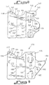
- needle retaining panel 81 is connected to needle protecting panel 82 through single perforate score 90, panel 82 being connected to suture winding panel 83 (which is also the rear panel of the fully folded retainer) through double perforate score 91, panel 83 being connected to fold-over panel 84 through double perforate score 92.
- Diamond-shaped cutouts 89 and 89' are provided along upper sloping edge 88 of panel 81 in the region receiving needle components 100 and 100' (Fig. 4) of two surgical suture-needle devices.
- needle retaining panel 81 is folded over at perforate score 90 upon needle protecting panel 82 and the surgical suture components of the combined suture-needle devices (not shown) are wound in a figure "8" pattern upon suture winding panel 83 with the aid of loading pins projecting through openings 96 in much the same manner as previously described in connection with the suture retainer embodiment of Figs. 1 and 2.
- Combined overlying panels 81 and 82 are thereafter folded over at double perforate score 91 upon suture winding panel 83 to slightly compress the wound sutures and retain them in place on panel 83.
- Panel 84 is then folded over at double perforate score 92 upon the reverse side of panel 82, die-cut locking tabs 97 and 98 on panel 84 cooperating with die-cut locking slots 97' and 98' on panel 82 to provide the nearly fully folded retainer shown in Fig. 5.
- outer extension panel 85 is folded over at double perforate score 93 upon both inner extension panel 86 and exposed needles 100 and 100' with die-cut tab locking 99 on panel 85 engaging the upper edge of fold-over panel 84 to provide the fully folded suture retainer shown in Fig. 6.
- inner extension panel 86 is advantageously provided with a die-cut separation line 95 and perforate score 95' which allows the entire combined extension panel 85, 86 to be conveniently separated from panel 83 or folded back upon itself thus permitting access to needles 100 and 100' from the reverse side of retainer 80 as well as from its front side. Even when combined extension 85, 86 is not-separated from panel 83, the combined extension may be folded back along separation line 94 and perforate score 95' to provide needle visibility and accessibility from the rear of retainer 80.
- Outer extension panel 85 possesses a knurled section 102 which facilitates the opening of fully closed retainer 80 by providing a surface for easy engagement of the lower section of extension panel 85.
- retainer 110 features four panels, namely, needle retaining panel 111, needle protecting panel 112, suture winding panel 113 and fold-over panel 114.
- Double perforated scores 120 and 121 define gussets which allow for expansion of the loaded retainer in its closed condition.
- Raised ribs 138a and 138b project outwards from the reverse sides of fold over panel 114 and extension panel 105, respectively.
- raised ribs 138a provide a slight concave bend to fold-over panel 114, which enables 114 to resist any tendency to thrust away from needle retainer panel 111.
- Needle protection panel 112 possesses a trapezoidal shaped locking slit 135.
- locking tab 130 folds back at a 180° angle upon its score line 132 and cooperates with closing slit 135 of panel 112 to provide a completely secured retainer.
- Triangular panel 136 folds over upon perforate score line 137 and secures a suture thread to retainer panel 113.
- Extension panel 105 possesses convex sides 127a and 127b which facilitate the opening of retainer 110 by operating room personnel. When retainer member 110 is in a fully closed position, convex sides 127a and 127b extend outwards from the sides of retainer 80 and provide two areas for easy engagement of extension panel 105.
- Needle retaining panel 111 possesses a sinusoidal serration configuration 117 and a pair of "J" cuts 119 similar in design and function to the corresponding configurations of retainer 40 of Fig. 3.
- Retainer 140 features four panels, namely, needle retaining panel 141, front cover panel 142, suture winding panel 143, and foldover panel 144.
- Double perforated scores 151 define a gusset which allows for expansion of the loaded retainer in its closed condition.
- Front cover panel 142 possesses an upper sloping edge 154 which slopes upward to form a rounded projection 155.
- Suture winding panel 143 is significantly narrower than the suture winding panels of other embodiments described herein. The narrower panel facilitates winding of the suture and minimizes the possibility that suture loops may become entangled.
- Suture winding panel 143 possesses triangular shaped extension panel 145 which folds over along perforated score line 146 to provide a needle protection flap in the loaded and closed condition of the retainer card. When panel 143 is folded over onto panel 142, slit 153 can be made to engage rounded projection 155 thus locking the two panels together.
- Bell-shaped fold-over panel 144 possesses a tab 156 which cooperates with slit 157 to secure a wound suture upon suture winding panel 143. Die cut 159 cooperates with die cut 160 to provide a snap-lock feature which maintains the retainer in the fully closed condition.
- retainer 170 possesses four panels, namely, needle-retainer panel 171, front cover panel 172, suture-winding panel 173 and fold-over panel 174.
- the openings 188 of suture winding panel 173 which receive the loaded pins are positioned further apart than in previous embodiments. This positioning reduces the likelihood of suture entanglement since the freedom of movement of the wound suture is limited to one direction (i.e., inwardly). In addition, loop positioning will be better achieved and secured by compression of adjoining panels more closely adjacent the fold-lines.
- Triangular fold-over panel 174 possesses outer edge 192 which, in the folded condition of the retainer, interlocks with slit 187 to secure the wound suture to suture winding panel 173.
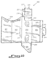
- retainer 200 possesses four panels, namely, needle retainer panel 201, front cover panel 202, suture winding panel 203, and fold over panel 204.
- Double perforated score lines 210, 211 and 212 constitute gussets which permit expansion of the retainer in its loaded, closed condition.
- Needle retainer panel 201 possesses foam block 208 which provides an alternate means of needle retention.
- Suture winding panel 203 possesses triangular extension panel 205 foldable along perforated line 206. Fold over panel 204 and extension panel 217 possess slightly raised ribs 207 and 222, respectively.
- Raised rib 207 imparts a slight concave bend to fold-over panel 204 which enables 204 to resist a tendency to thrust away from needle retainer panel 201.
- Raised rib 222 functions in a similar manner where extension panel 217 is concerned.
- Locking tab 213 is defined along double score line 214. When retainer 200 is in the fully closed condition, locking tab 213 folds back along double score line 214 to cooperate with closing slit 215 of panel 202 and provide a completely secured retainer. In the closed position, outer extension panel 217 folds over at double perforated line 218. Tab 221 folds along arcuate perforated line 223 to fit under front cover panel 202 thus providing protection for the secured needle.
- the retainers of the invention can be packaged within, for example, a foil package or a so-called "breather pouch" (not shown).
Landscapes
- Health & Medical Sciences (AREA)
- Surgery (AREA)
- Life Sciences & Earth Sciences (AREA)
- Medical Informatics (AREA)
- Nuclear Medicine, Radiotherapy & Molecular Imaging (AREA)
- Engineering & Computer Science (AREA)
- Biomedical Technology (AREA)
- Heart & Thoracic Surgery (AREA)
- Dentistry (AREA)
- Molecular Biology (AREA)
- Animal Behavior & Ethology (AREA)
- General Health & Medical Sciences (AREA)
- Public Health (AREA)
- Veterinary Medicine (AREA)
- Surgical Instruments (AREA)
- Materials For Medical Uses (AREA)
Claims (20)
- Nahtmaterialaufnahme (10), enthaltend eine Vorrichtung aus Nadel und Nahtmaterial, wobei die Aufnahme umfaßt: ein erstes Feld (11), welches als Nadelhaltefeld dient, ein mit dem ersten Feld (11) verbundenes und als Deckfeld dienendes zweites Feld (12), ein mit dem zweiten Feld (12) verbundenes und als Nahtmaterialwickelfeld dienendes drittes Feld (13), sowie ein mit dem dritten Feld (13) verbundenes und als Umfaltfeld dienendes viertes Feld (14), wobei die Aufnahme in einen zusammengefalteten Zustand faltbar ist, in welchem das erste Feld (11) über das zweite Feld (12) gefaltet ist, und dann das zweite Feld (12) und das erste Feld (11) zusammen über das dritte Feld (13) gefaltet sind, so daß das erste Feld (11) zwischen dem zweiten (12) und dritten Feld (13) liegt, und dadurch gekennzeichnet, daß das erste Feld (11) Nadelbefestigungseinrichtungen (23, 24) besitzt, um die Spitze und den Schaft des Nadelbestandteils (30) von mindestens einer Vorrichtung aus kombinierter chirurgischer Nadel und Nahtmaterial an einem schrägen oberen Rand (27) desselben zu befestigen, und das zweite Feld (12) einen schrägen oberen Rand (28) aufweist, der im zusammengefalteten Zustand der Nahtmaterialaufnahme (10) für ein Freiliegen jeder am ersten Feld (11) befestigten Nadel (30) oberhalb des schrägen oberen Randes (27, 28) des besagten ersten (11) und zweiten (12) Feldes sorgt.
- Nahtmaterialaufnahme (10) nach Anspruch 1, dadurch gekennzeichnet, daß das dritte Feld (13) den Nahtmaterialbestandteil von mindestens einer Vorrichtung aus kombinierter chirurgischer Nadel und Nahtmaterial aufnimmt, wobei es zu diesem Zweck eine Mehrzahl von Öffnungen (18, 96) für Nahtmaterialbestandteil-Bestückungsbolzen aufweist.
- Nahtmaterialaufnahme nach Anspruch 1 oder 2, dadurch gekennzeichnet, daß der Rand von jeder der Verbindungsstellen des ersten und des zweiten Feldes, des zweiten und des dritten Feldes und des dritten und des vierten Feldes eine Einbuchtung (20, 21, 22) aufweist, so daß die Einbuchtungen im zusammengefalteten Zustand der Aufnahme verhindern, daß das Nahtmaterial zwischen den Feldern hängenbleibt, wenn die Felder zusammengefaltet sind.
- Nahtmaterialaufnahme nach Anspruch 1, 2 oder 3, dadurch gekennzeichnet, daß das erste Feld ein Verlängerungsfeld (53) aufweist, das entlang eines schrägen oberen Randes (27) als Einheit mit dem besagten ersten Feld ausgebildet ist.
- Nahtmaterialaufnahme nach Anspruch 4, dadurch gekennzeichnet, daß das besagte Verlängerungsfeld (53) so angepaßt ist, daß es sich auf seinem schrägen oberen Rand (27) falten läßt, um eine Nadel zwischen dem besagten oberen Rand und dem besagten zweiten Feld im Eingriff zu halten.
- Nahtmaterialaufnahme nach Anspruch 4 oder 5, dadurch gekennzeichnet, daß das besagte Verlängerungsfeld durch den besagten Rand daran gehindert wird, sich flach gegen das besagte erste Feld anzulegen.
- Nahtmaterialaufnahme nach Anspruch 4, 5 oder 6, dadurch gekennzeichnet, daß eine Nadelbefestigungseinrichtung so angeordnet ist, und sich das erste Feld (11) und das Verlängerungsfeld (53) so am schrägen oberen Rand (27) falten lassen, daß der (die) an einem derartigen Rand befestigte(n) Nadelbestandteil(e) geschützt ist (sind).
- Nahtmaterialaufnahme nach einem beliebigen der vorangehenden Ansprüche, dadurch gekennzeichnet, daß die Einrichtung zum Befestigen eines Nadelbestandteils an derselben einen Schaumstoffblock (208) umfaßt.
- Nahtmaterialaufnahme nach einem beliebigen der vorangehenden Ansprüche, dadurch gekennzeichnet, daß die Einrichtung zum Befestigen eines Nadelbestandteils am ersten Feld einen Ausschnitt umfaßt, der mit dem oberen Rand des besagten Feldes verbunden oder auf diesem gebildet ist, um Platz zu haben für einen Hindurchtritt von Sterilisiergas.
- Nahtmaterialaufnahme nach Anspruch 4 oder einem beliebigen der von Anspruch 4 abhängigen Ansprüche 5 bis 9, dadurch gekennzeichnet, daß das Verlängerungsfeld für eine weitere Befestigung eines Nadelbestandteils an demselben mindestens einen Zahneinschnitt entlang seines freien Randes besitzt.
- Nahtmaterialaufnahme nach einem beliebigen der vorangehenden Ansprüche, dadurch gekennzeichnet, daß das dritte Feld ein Verlängerungsfeld (105) besitzt, welches sich auf die freiliegende(n) Nadel(n) umfalten läßt, um einen zusätzlichen Schutz für diese bereitzustellen.
- Nahtmaterialaufnahme nach Anspruch 11, dadurch gekennzeichnet, daß das Verlängerungsfeld (105) mit dem dritten Feld durch eine Einrichtung verbunden ist, die sein Abtrennen von diesem erleichtert.
- Nahtmaterialaufnahme nach Anspruch 11 oder 12, dadurch gekennzeichnet, daß das Verlängerungsfeld (105) mit dem dritten Feld durch eine Einrichtung verbunden ist, die ein Umfalten des besagten Verlängerungsfeldes relativ zu dem besagten dritten Feld erleichtert, um so für eine rasche Sichtbarkeit der Nadeln zu sorgen.
- Nahtmaterialaufnahme nach einem beliebigen der Ansprüche 11, 12 oder 13, dadurch gekennzeichnet, daß das Verlängerungsfeld (105) konvex geformte Seiten (127) aufweist, so daß sich die Seiten im zusammengefalteten Zustand der Aufnahme von jeder Seite der Aufnahme aus nach außen zu erstrecken, um ein Profil zu schaffen, welches das Öffnen der Aufnahme erleichtert.
- Nahtmaterialaufnahme nach einem beliebigen der Ansprüche 11 bis 14, dadurch gekennzeichnet, daß das Verlängerungsfeld eine Verriegelungszunge aufweist, um das besagte Verlängerungsfeld im vollständig geschlossenen Zustand am vierten Feld zu befestigen.
- Nahtmaterialaufnahme nach einem beliebigen der Ansprüche 11 bis 15, dadurch gekennzeichnet, daß das Verlängerungsfeld eine gerändelte Greifoberfläche besitzt.
- Nahtmaterialaufnahme nach einem beliebigen der vorangehenden Ansprüche, dadurch gekennzeichnet, daß das vierte Feld eine erhöhte Rippe besitzt, die aus der Rückseite des vierten Feldes nach außen ragt, so daß die besagte Rippe im zusammengefalteten Zustand der Aufnahme dem vierten Feld eine konkave Biegung verleiht, die jeglicher Neigung des vierten Feldes zum Wegdrücken vom ersten Feld entgegenwirkt.
- Nahtmaterialaufnahme nach Anspruch 11 oder einem beliebigen der von Anspruch 11 abhängigen Ansprüche 12 bis 17, dadurch gekennzeichnet, daß das Verlängerungsfeld des dritten Feldes für eine weitere Befestigung eines Nahtmaterialfadens an dem besagten dritten Feld geformt und angeordnet ist.
- Nahtmaterialaufnahme nach einem beliebigen der vorangehenden Ansprüche, dadurch gekennzeichnet, daß das zweite Feld einen trapezförmigen Schlitz besitzt, und das vierte Feld eine Verriegelungszunge besitzt, so daß sich die besagte Verriegelungszunge im zusammengefalteten Zustand der Aufnahme unter einem Winkel von 180° auf sich selbst zurückfalten läßt und mit dem besagten trapezförmigen Schlitz zusammenwirkt, um die Felder der Aufnahme miteinander zu verriegeln.
- Nahtmaterialaufnahme nach einem beliebigen der vorangehenden Ansprüche, dadurch gekennzeichnet, daß das zweite Feld (143) einen nach oben gerundeten Vorsprung (155) besitzt, und das dritte Feld ein dreieckförmiges Verlängerungsfeld (145) besitzt, das entlang einer angewinkelten perforierten Linie (146) abgegrenzt ist und in einer horizontalen Schnittlinie (153) endet, so daß der besagte nach oben runde Vorsprung (155) im zusammengefalteten Zustand der Aufnahme mit der besagten horizontalen Schnittlinie zusammenwirkt, um die Felder miteinander zu verriegeln.
Applications Claiming Priority (2)
| Application Number | Priority Date | Filing Date | Title |
|---|---|---|---|
| US52922290A | 1990-05-25 | 1990-05-25 | |
| US529222 | 1990-05-25 |
Publications (2)
| Publication Number | Publication Date |
|---|---|
| EP0458432A1 EP0458432A1 (de) | 1991-11-27 |
| EP0458432B1 true EP0458432B1 (de) | 1995-05-03 |
Family
ID=24109016
Family Applications (1)
| Application Number | Title | Priority Date | Filing Date |
|---|---|---|---|
| EP91301067A Expired - Lifetime EP0458432B1 (de) | 1990-05-25 | 1991-02-11 | Innenbeutel für eine Nähfaden und Nadel kombinierende chirurgische Vorrichtung |
Country Status (8)
| Country | Link |
|---|---|
| EP (1) | EP0458432B1 (de) |
| JP (1) | JPH05103789A (de) |
| AT (1) | ATE121920T1 (de) |
| AU (1) | AU649241B2 (de) |
| CA (1) | CA2034989C (de) |
| DE (1) | DE69109364T2 (de) |
| ES (1) | ES2071910T3 (de) |
| FI (1) | FI911208A7 (de) |
Families Citing this family (10)
| Publication number | Priority date | Publication date | Assignee | Title |
|---|---|---|---|---|
| US5226535A (en) * | 1992-02-14 | 1993-07-13 | Ethicon, Inc. | Package for endoscopic suture loop and cannula |
| US5335783A (en) * | 1992-04-16 | 1994-08-09 | United States Surgical Corporation | Retainer for a combined surgical needle-suture device |
| CA2091317C (en) * | 1992-06-19 | 1998-10-06 | Hans-Jurgen F. Sinn | Needle shield device for surgical packages |
| DE4240831C1 (de) * | 1992-12-04 | 1993-10-07 | Braun Melsungen Ag | Nahtmaterialpackung |
| US5348146A (en) * | 1993-02-11 | 1994-09-20 | American Cyanamid Co. | Suture package |
| US5487469A (en) * | 1994-01-26 | 1996-01-30 | Ethicon, Inc. | Package for endoscopic instrument |
| US7891485B2 (en) * | 2008-04-11 | 2011-02-22 | Tyco Healthcare Group Lp | Suture retainer with rib members |
| WO2011092925A1 (ja) * | 2010-01-29 | 2011-08-04 | Kimura Fujita | 条体の収容容器 |
| US9387065B2 (en) * | 2014-03-28 | 2016-07-12 | Medos International Sàrl | Implant and filament management device |
| BR102015007027B1 (pt) | 2014-03-28 | 2022-02-08 | Medos International Sàrl | Dispositivo de gerenciamento de implante e filamento |
Family Cites Families (16)
| Publication number | Priority date | Publication date | Assignee | Title |
|---|---|---|---|---|
| US3162307A (en) * | 1963-07-10 | 1964-12-22 | Ethicon Inc | Surgical package |
| US4063638A (en) * | 1977-03-16 | 1977-12-20 | American Cyanamid Company | Direct dispensing packaging of surgical sutures |
| US4120395A (en) * | 1977-09-02 | 1978-10-17 | Ethicon, Inc. | Package for double-armed sutures |
| US4249656A (en) * | 1979-10-15 | 1981-02-10 | Ethicon, Inc. | Suture package |
| US4253563A (en) * | 1980-05-15 | 1981-03-03 | Ethicon, Inc. | Multistrand suture package |
| DE3032037C2 (de) * | 1980-08-26 | 1982-05-19 | B. Braun Melsungen Ag, 3508 Melsungen | Packung für chirurgisches Nahtmaterial |
| US4574948A (en) * | 1981-03-06 | 1986-03-11 | Howmedica, Inc. | Linear fold armed suture |
| US4413727A (en) * | 1982-03-18 | 1983-11-08 | Ethicon Inc. | Folder retainer for surgical sutures |
| US4406363A (en) * | 1982-09-24 | 1983-09-27 | Ethicon, Inc. | Folder retainer for multistrand surgical sutures |
| US4574957A (en) * | 1984-03-30 | 1986-03-11 | Ethicon, Inc. | Packing of surgical needle |
| US4533041A (en) * | 1984-07-31 | 1985-08-06 | Ethicon, Inc. | Multistrand suture package with single strand suture dispensing |
| US4572363A (en) * | 1985-07-10 | 1986-02-25 | Ethicon, Inc. | Suture retainer for multistrand sutures with single strand suture dispensing |
| US4615435A (en) * | 1985-12-19 | 1986-10-07 | Ethicon, Inc. | Retainer for surgical sutures |
| US4708241A (en) * | 1986-08-06 | 1987-11-24 | American Cyanamid Company | Suture package |
| JPH0525605Y2 (de) * | 1987-01-26 | 1993-06-29 | ||
| JPS63288146A (ja) * | 1987-05-20 | 1988-11-25 | Nippon Medical Supply Corp | 縫合糸包装用台紙 |
-
1991
- 1991-01-25 CA CA002034989A patent/CA2034989C/en not_active Expired - Lifetime
- 1991-02-01 AU AU70192/91A patent/AU649241B2/en not_active Ceased
- 1991-02-11 EP EP91301067A patent/EP0458432B1/de not_active Expired - Lifetime
- 1991-02-11 DE DE69109364T patent/DE69109364T2/de not_active Expired - Lifetime
- 1991-02-11 ES ES91301067T patent/ES2071910T3/es not_active Expired - Lifetime
- 1991-02-11 AT AT91301067T patent/ATE121920T1/de not_active IP Right Cessation
- 1991-02-22 JP JP3112671A patent/JPH05103789A/ja active Pending
- 1991-03-12 FI FI911208A patent/FI911208A7/fi unknown
Also Published As
| Publication number | Publication date |
|---|---|
| DE69109364T2 (de) | 1995-10-12 |
| CA2034989C (en) | 1995-06-27 |
| AU7019291A (en) | 1991-11-28 |
| ES2071910T3 (es) | 1995-07-01 |
| JPH05103789A (ja) | 1993-04-27 |
| FI911208A0 (fi) | 1991-03-12 |
| ATE121920T1 (de) | 1995-05-15 |
| FI911208L (fi) | 1991-11-26 |
| AU649241B2 (en) | 1994-05-19 |
| FI911208A7 (fi) | 1991-11-26 |
| CA2034989A1 (en) | 1991-11-26 |
| DE69109364D1 (de) | 1995-06-08 |
| EP0458432A1 (de) | 1991-11-27 |
Similar Documents
| Publication | Publication Date | Title |
|---|---|---|
| US5121836A (en) | Retainer for combined surgical suture-needle device | |
| US5425445A (en) | Retainer for a combined surgical suture-needle device | |
| US4406363A (en) | Folder retainer for multistrand surgical sutures | |
| US4089409A (en) | Package for multistrand surgical sutures | |
| US3444994A (en) | Suture package | |
| US5197597A (en) | Suture retainer | |
| US4572363A (en) | Suture retainer for multistrand sutures with single strand suture dispensing | |
| CA1149339A (en) | Suture package | |
| US5101968A (en) | Retainers for needled surgical sutures | |
| US3939969A (en) | Suture package | |
| US4126221A (en) | Package for multiple surgical sutures | |
| US4034850A (en) | Package for double-armed sutures with self-centering pledgets | |
| KR880001187B1 (ko) | 봉합사용 포울더(folder) | |
| US6016905A (en) | Surgical suture retainer package | |
| EP1842492B1 (de) | Verpackung für chirurgische Nahtinstrumente | |
| US5390782A (en) | Needle shield device for surgical packages | |
| EP0458432B1 (de) | Innenbeutel für eine Nähfaden und Nadel kombinierende chirurgische Vorrichtung | |
| US5127518A (en) | Package for surgical sutures | |
| US5533611A (en) | Folding package for surgical products | |
| EP0454289B1 (de) | Verpackung für mit Nadeln versehene Nähfäden | |
| US5341622A (en) | Method of folding of pack for holding suture material | |
| EP1013230B1 (de) | Verpackung zur mehrsträngigen Aufbewahrung von chirurgischem Nahtmaterial | |
| US5092455A (en) | Suture retainer | |
| JPH0852146A (ja) | 手術用縫い糸のための包装 | |
| EP0722694A2 (de) | Verpackung für mit einer Nadel versehene chirurgische Nähfäden |
Legal Events
| Date | Code | Title | Description |
|---|---|---|---|
| PUAI | Public reference made under article 153(3) epc to a published international application that has entered the european phase |
Free format text: ORIGINAL CODE: 0009012 |
|
| AK | Designated contracting states |
Kind code of ref document: A1 Designated state(s): AT BE CH DE DK ES FR GB GR IT LI LU NL SE |
|
| 17P | Request for examination filed |
Effective date: 19920526 |
|
| 17Q | First examination report despatched |
Effective date: 19920921 |
|
| GRAA | (expected) grant |
Free format text: ORIGINAL CODE: 0009210 |
|
| AK | Designated contracting states |
Kind code of ref document: B1 Designated state(s): AT BE CH DE DK ES FR GB GR IT LI LU NL SE |
|
| PG25 | Lapsed in a contracting state [announced via postgrant information from national office to epo] |
Ref country code: DK Effective date: 19950503 Ref country code: AT Effective date: 19950503 Ref country code: GR Free format text: LAPSE BECAUSE OF FAILURE TO SUBMIT A TRANSLATION OF THE DESCRIPTION OR TO PAY THE FEE WITHIN THE PRESCRIBED TIME-LIMIT Effective date: 19950503 Ref country code: NL Free format text: LAPSE BECAUSE OF FAILURE TO SUBMIT A TRANSLATION OF THE DESCRIPTION OR TO PAY THE FEE WITHIN THE PRESCRIBED TIME-LIMIT Effective date: 19950503 Ref country code: BE Effective date: 19950503 Ref country code: CH Effective date: 19950503 Ref country code: LI Effective date: 19950503 |
|
| REF | Corresponds to: |
Ref document number: 121920 Country of ref document: AT Date of ref document: 19950515 Kind code of ref document: T |
|
| REF | Corresponds to: |
Ref document number: 69109364 Country of ref document: DE Date of ref document: 19950608 |
|
| REG | Reference to a national code |
Ref country code: ES Ref legal event code: FG2A Ref document number: 2071910 Country of ref document: ES Kind code of ref document: T3 |
|
| ITF | It: translation for a ep patent filed | ||
| PG25 | Lapsed in a contracting state [announced via postgrant information from national office to epo] |
Ref country code: SE Effective date: 19950803 |
|
| REG | Reference to a national code |
Ref country code: CH Ref legal event code: PL |
|
| ET | Fr: translation filed | ||
| NLV1 | Nl: lapsed or annulled due to failure to fulfill the requirements of art. 29p and 29m of the patents act | ||
| PG25 | Lapsed in a contracting state [announced via postgrant information from national office to epo] |
Ref country code: ES Free format text: LAPSE BECAUSE OF NON-PAYMENT OF DUE FEES Effective date: 19960212 |
|
| PG25 | Lapsed in a contracting state [announced via postgrant information from national office to epo] |
Ref country code: LU Free format text: LAPSE BECAUSE OF NON-PAYMENT OF DUE FEES Effective date: 19960229 |
|
| PLBE | No opposition filed within time limit |
Free format text: ORIGINAL CODE: 0009261 |
|
| STAA | Information on the status of an ep patent application or granted ep patent |
Free format text: STATUS: NO OPPOSITION FILED WITHIN TIME LIMIT |
|
| 26N | No opposition filed | ||
| REG | Reference to a national code |
Ref country code: ES Ref legal event code: FD2A Effective date: 19990301 |
|
| REG | Reference to a national code |
Ref country code: GB Ref legal event code: IF02 |
|
| PG25 | Lapsed in a contracting state [announced via postgrant information from national office to epo] |
Ref country code: IT Free format text: LAPSE BECAUSE OF NON-PAYMENT OF DUE FEES;WARNING: LAPSES OF ITALIAN PATENTS WITH EFFECTIVE DATE BEFORE 2007 MAY HAVE OCCURRED AT ANY TIME BEFORE 2007. THE CORRECT EFFECTIVE DATE MAY BE DIFFERENT FROM THE ONE RECORDED. Effective date: 20050211 |
|
| PGFP | Annual fee paid to national office [announced via postgrant information from national office to epo] |
Ref country code: FR Payment date: 20100303 Year of fee payment: 20 |
|
| PGFP | Annual fee paid to national office [announced via postgrant information from national office to epo] |
Ref country code: GB Payment date: 20100224 Year of fee payment: 20 Ref country code: DE Payment date: 20100226 Year of fee payment: 20 |
|
| REG | Reference to a national code |
Ref country code: DE Ref legal event code: R071 Ref document number: 69109364 Country of ref document: DE |
|
| REG | Reference to a national code |
Ref country code: GB Ref legal event code: PE20 Expiry date: 20110210 |
|
| PG25 | Lapsed in a contracting state [announced via postgrant information from national office to epo] |
Ref country code: GB Free format text: LAPSE BECAUSE OF EXPIRATION OF PROTECTION Effective date: 20110210 |
|
| PG25 | Lapsed in a contracting state [announced via postgrant information from national office to epo] |
Ref country code: DE Free format text: LAPSE BECAUSE OF EXPIRATION OF PROTECTION Effective date: 20110211 |