EP0458506B1 - Einteilig ausgebildetes Skalpell für Kontaktlaserchirurgie - Google Patents
Einteilig ausgebildetes Skalpell für Kontaktlaserchirurgie Download PDFInfo
- Publication number
- EP0458506B1 EP0458506B1 EP91304300A EP91304300A EP0458506B1 EP 0458506 B1 EP0458506 B1 EP 0458506B1 EP 91304300 A EP91304300 A EP 91304300A EP 91304300 A EP91304300 A EP 91304300A EP 0458506 B1 EP0458506 B1 EP 0458506B1
- Authority
- EP
- European Patent Office
- Prior art keywords
- scalpel
- fiber
- laser
- ceramic
- optical conductor
- Prior art date
- Legal status (The legal status is an assumption and is not a legal conclusion. Google has not performed a legal analysis and makes no representation as to the accuracy of the status listed.)
- Expired - Lifetime
Links
- 238000002430 laser surgery Methods 0.000 title description 2
- 239000000919 ceramic Substances 0.000 claims abstract description 35
- 239000013307 optical fiber Substances 0.000 claims abstract description 26
- 230000003287 optical effect Effects 0.000 claims description 19
- 239000004020 conductor Substances 0.000 claims description 17
- 238000005520 cutting process Methods 0.000 claims description 10
- 239000002320 enamel (paints) Substances 0.000 claims description 7
- 230000003014 reinforcing effect Effects 0.000 claims description 2
- 239000000835 fiber Substances 0.000 abstract description 56
- 239000000463 material Substances 0.000 abstract description 5
- 229910010293 ceramic material Inorganic materials 0.000 abstract description 4
- 238000000034 method Methods 0.000 abstract description 4
- 210000003298 dental enamel Anatomy 0.000 abstract description 2
- PNEYBMLMFCGWSK-UHFFFAOYSA-N aluminium oxide Inorganic materials [O-2].[O-2].[O-2].[Al+3].[Al+3] PNEYBMLMFCGWSK-UHFFFAOYSA-N 0.000 description 8
- 230000008901 benefit Effects 0.000 description 5
- 238000013461 design Methods 0.000 description 5
- 239000000523 sample Substances 0.000 description 5
- 238000001816 cooling Methods 0.000 description 4
- 230000008878 coupling Effects 0.000 description 4
- 238000010168 coupling process Methods 0.000 description 4
- 238000005859 coupling reaction Methods 0.000 description 4
- 239000006185 dispersion Substances 0.000 description 4
- 238000003754 machining Methods 0.000 description 4
- 239000011248 coating agent Substances 0.000 description 3
- 238000000576 coating method Methods 0.000 description 3
- 229910052594 sapphire Inorganic materials 0.000 description 3
- 239000010980 sapphire Substances 0.000 description 3
- 230000009471 action Effects 0.000 description 2
- 230000008030 elimination Effects 0.000 description 2
- 238000003379 elimination reaction Methods 0.000 description 2
- 239000013305 flexible fiber Substances 0.000 description 2
- 238000010438 heat treatment Methods 0.000 description 2
- 239000007788 liquid Substances 0.000 description 2
- 230000014759 maintenance of location Effects 0.000 description 2
- 238000004519 manufacturing process Methods 0.000 description 2
- 230000005499 meniscus Effects 0.000 description 2
- 230000005855 radiation Effects 0.000 description 2
- 230000002459 sustained effect Effects 0.000 description 2
- XLYOFNOQVPJJNP-UHFFFAOYSA-N water Substances O XLYOFNOQVPJJNP-UHFFFAOYSA-N 0.000 description 2
- 239000004593 Epoxy Substances 0.000 description 1
- VYPSYNLAJGMNEJ-UHFFFAOYSA-N Silicium dioxide Chemical compound O=[Si]=O VYPSYNLAJGMNEJ-UHFFFAOYSA-N 0.000 description 1
- 239000011358 absorbing material Substances 0.000 description 1
- 230000001154 acute effect Effects 0.000 description 1
- 239000011324 bead Substances 0.000 description 1
- 230000005540 biological transmission Effects 0.000 description 1
- 238000005422 blasting Methods 0.000 description 1
- 230000005587 bubbling Effects 0.000 description 1
- 238000005253 cladding Methods 0.000 description 1
- 230000001010 compromised effect Effects 0.000 description 1
- 238000010276 construction Methods 0.000 description 1
- 239000002178 crystalline material Substances 0.000 description 1
- 230000001351 cycling effect Effects 0.000 description 1
- 230000006378 damage Effects 0.000 description 1
- 230000006866 deterioration Effects 0.000 description 1
- 229910003460 diamond Inorganic materials 0.000 description 1
- 239000010432 diamond Substances 0.000 description 1
- 230000002708 enhancing effect Effects 0.000 description 1
- 230000001747 exhibiting effect Effects 0.000 description 1
- 238000001125 extrusion Methods 0.000 description 1
- 239000012530 fluid Substances 0.000 description 1
- 239000005350 fused silica glass Substances 0.000 description 1
- 238000010348 incorporation Methods 0.000 description 1
- 238000007373 indentation Methods 0.000 description 1
- 238000003780 insertion Methods 0.000 description 1
- 230000037431 insertion Effects 0.000 description 1
- 230000003993 interaction Effects 0.000 description 1
- 210000003127 knee Anatomy 0.000 description 1
- 238000012423 maintenance Methods 0.000 description 1
- 238000002844 melting Methods 0.000 description 1
- 230000008018 melting Effects 0.000 description 1
- 239000002184 metal Substances 0.000 description 1
- 238000000465 moulding Methods 0.000 description 1
- 238000012829 orthopaedic surgery Methods 0.000 description 1
- 230000000399 orthopedic effect Effects 0.000 description 1
- 230000002035 prolonged effect Effects 0.000 description 1
- 230000000644 propagated effect Effects 0.000 description 1
- 230000001681 protective effect Effects 0.000 description 1
- 230000009467 reduction Effects 0.000 description 1
- 230000035939 shock Effects 0.000 description 1
- 238000001356 surgical procedure Methods 0.000 description 1
- 238000012546 transfer Methods 0.000 description 1
- 230000007704 transition Effects 0.000 description 1
Images

Classifications
-
- A—HUMAN NECESSITIES
- A61—MEDICAL OR VETERINARY SCIENCE; HYGIENE
- A61B—DIAGNOSIS; SURGERY; IDENTIFICATION
- A61B18/00—Surgical instruments, devices or methods for transferring non-mechanical forms of energy to or from the body
- A61B18/18—Surgical instruments, devices or methods for transferring non-mechanical forms of energy to or from the body by applying electromagnetic radiation, e.g. microwaves
- A61B18/20—Surgical instruments, devices or methods for transferring non-mechanical forms of energy to or from the body by applying electromagnetic radiation, e.g. microwaves using laser
- A61B18/22—Surgical instruments, devices or methods for transferring non-mechanical forms of energy to or from the body by applying electromagnetic radiation, e.g. microwaves using laser the beam being directed along or through a flexible conduit, e.g. an optical fibre; Couplings or hand-pieces therefor
Definitions
- the present invention relates to scalpels for laser surgery, in particular, to scalpels intended for use in conjunction with, or as an integral member of, a flexible optical fiber delivery system.
- Such delivery systems are generally used, for example, with Nd:Yag and other lasers of wavelength suitable for the efficient transfer of laser energy through an optical fiber medium.
- WO-A-90/01907 describes a dental laser assembly which uses a fibre optic delivery system and a pulsed laser source. Various forms of replaceable tip are described, through which a fibre optic element extends.
- the present scalpel finds particular application in orthopaedic surgery, for example, in the removal of damaged meniscus from the knee.
- the operative site for such a procedure is commonly and preferably surrounded by water. This presence of water, however, creates significant problems for laser scalpels of conventional design.
- the tip region of the contact scalpel necessarily heats following any sustained interval of cutting.
- the heated tip is suddenly exposed and immersed in the relatively cool liquid surrounding the cut location thereby causing a corresponding rapid cooling of the tip.
- This cooling has been known to weaken or even fracture the sapphire or other crystalline material of which conventional laser scalpels are fabricated.
- the laser scalpel of the present invention has been developed to overcome this and certain other known problems associated with conventional non-unitary scalpel configurations.
- a laser scalpel for orthopaedic and other surgical applications, comprising: an elongate optical laser energy conductor of generally uniform cross-section having a laser energy inlet and a laser energy irradiation outlet; a support member for said conductor, the support member having an opening extending therethrough from a first, proximal end to a second, distal end, with the optical conductor positioned within said opening; the support member comprising a rigid ceramic body at the distal end of the support member; characterised in that the outlet of the optical conductor has a contact surface for direct engagement with tissue to be operated on; and an enamel coating is provided on the distal end of the support member and optical conductor, thereby to enhance scalpel side-cutting and irradiation angle.
- the present scalpel does not utilize conventional sapphire or similar optically transparent contact members--at least, not in such configuration as to expose the material to the rigours of extreme temperature cycling. Rather, the optically active elements of the present invention are at least partially encased within, and protected by, an opaque ceramic ferrule, preferably of alumina, which material exhibits numerous advantageous properties with particular reference to aqueous environments.
- the coefficient of thermal conductivity of alumina is quite low.
- the heat which is generated at the distal top end region of the probe is not propagated along the probe and handle and therefore does not ordinarily heat non-active portions of the scalpel system.
- this heat is this heat communicated to the ferrule core where such fiber is located.
- a further and very significant property of alumina is its resistance to thermal shock-induced fracturing. This problem is particularly acute, as noted, in certain orthopaedic applications where the scalpel must be withdrawn from the meniscus through its surrounding fluid environment.
- Alumina has been found to exhibit greater tolerance to the lateral shear loads to which a scalpel is invariably subjected during any cutting procedure.
- the alumina ferrule is not, however, an active element of the scalpel in an optical sense. Indeed, alumina and most similar ceramic materials are opaque to the laser wavelengths of interest.
- optical focusing of the laser energy to the tip end region of the scalpel is achieved by placement of a narrow optical fiber within the ferrule, along the central axis thereof.
- This fiber is of uniform diameter and is preferably formed as an extension, in whole or in part, of the delivery system optical fiber, i.e., the fiber through which the laser energy is conveyed from the laser to the operative site.
- a fiber of greater diameter is employed with the fiber and ceramic ferrule combination being ground or otherwise machined to form a tapered conical profile.
- the fiber will be seen to extend forwardly of the reinforcing ceramic ferrule.
- the present scalpel provides, in addition to the above-enumerated advantages associated with the ceramic ferrule itself, the elimination of the interface between fiber and scalpel contact member. This advantage may be realized with either the narrow or wider tapered fiber embodiments of the present invention.
- This interface represents a perennial problem area in laser probe and scalpel implementation.
- the threaded connectors which affix the scalpel to the fiber optic delivery system must be of accurate design, thread, placement, and construction in order to assure proper alignment between the delivery fiber and the scalpel.
- the metallic couplings expensive, but their retention often requires grooves or other indentations in the sapphire thereby causing potential stress breakage points.
- the inherent coupling losses associated with any coupling of laser energy from one medium to another are the inherent coupling losses. These losses translate directly into heat generated at coupling interfaces which, in turn, must be conducted away from this interface if sustained scalpel operation, particularly at higher power levels, is contemplated.
- the angle of dispersion from the end of a bald, unfocused optical fiber is generally rather narrow, e.g. not above 10 degrees, and therefore is not appropriate for many surgical applications.
- the dispersion angle for conventional sapphire laser probes is approximately 25-35 degrees.
- the narrow fiber embodiment of the present scalpel overcomes these restrictions by limiting the diameter of the ceramic ferrule in the tip end region, preferably to about twice the fiber diameter or less. Further, the fiber is extended into flush relationship with the distal end of the ceramic thereby permitting or causing the corresponding distal end of the fiber to, as presently understood, partially liquify and/or recrystallize, in turn, resulting in a wider energy dispersion profile.
- the ceramic ferrule serves these additional functions including the support of the otherwise highly flexible fiber as well as the maintenance of the integrity of the distal portion of such fiber when the latter is subjected to the elevated temperature regime associated with actual scalpel operation.
- the fiber itself generally defines a tapered conical extension from the ceramic ferrule and serves to contain or focus the laser energy to the tip end of the tapered fiber.
- an optically transparent enamel is baked onto the surface of scalpel, generally from the tip region back between 1 and 2 mm.
- This coating may advantageously contain infrared absorbing material, although such is not required for the practice of this invention.
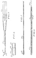
- Handpiece 12 is of conventional design having a widened body portion or handle 14 with a tubular member or wand 16 extending therefrom.
- a channel or opening 18 ( Figure 2) is provided in the handpiece through which an optical fiber system 20 passes.
- This system is also of known design and includes an optical fiber 22, preferably of fused silica, through which the laser energy is channelled and a protective sheathing 24 concentrically thereon.
- optical fibers of varying diameters are found in connection with known laser probes and scalpels, a fiber of relatively narrow diameter, for example 200 microns, is preferred for the present extended-fiber ceramic scalpel--this by reason that the delivery system fiber extends through, and thereby defines, the entire optical path of the scalpel itself.
- the present scalpel includes a tapered or conically-shaped ferrule 26 fabricated from a ceramic material of high shear strength and low thermal conductivity.
- Alumina has been found to be satisfactory and is preferred in view of its extremely low thermal conductivity (0.07 cal/cm sec °C) and its proven resistance to mechanical failure under ordinary surgical conditions.
- the present ceramic scalpel 10 is positioned and affixed to the distal end of the handpiece wand 16. More specifically, the rear or input portion 28 of the ferrule is machined, or molded, to a diameter generally equal to the inside dimension of the tubular member thereby permitting the ferrule to be snugly received therein.
- the diameter of the cylindrical body portion 30 of the ferrule is preferably the same as that of the wand 16 thereby defining a smooth, even transition between the scalpel and handpiece.
- the forward scalpel region 32 is of conical profile having, in one preferred arrangement, a taper angle of approximately 8 degrees. This taper extends from its widest diameter generally, as noted, equal to that of the tubular member, to a narrow cross-section at the scalpel tip end 34 preferably in the order of twice the diameter of the fiber or, in the present case, to a diameter of 400 microns.
- the enlarged side elevation or end view of Figure 3 illustrates the cylindrical body, the narrow tip, and fiber diameters, respectively, as 36, 38, and 40.
- tip end diameters 38 may be utilized. However, proper scalpel cutting action may be compromised as the tip end diameter is increased. Tip diameters in excess of 3 or 4 times that of the fiber are not, as presently understood, suitable.
- a hole or passage 42 is provided along the longitudinal scalpel axis through which an extended portion of fiber 22 is passed.
- This hole is of appropriate diameter to snugly receive fiber 22 therein, although retention of the fiber within the scalpel may be assured by, for example, epoxying the fiber to the rear portion of the scalpel as shown at 46 ( Figure 2).
- the distal end 44 of this fiber is positioned, or cleaved, flush with the scalpel tip end 34.
- the present ferrule including machining, molding, and drawing or extrusion.
- the preferred manner of manufacture is by drawing or extruding the ferrule with a pin member in the die to form the axial fiber passage 42.
- the present extended fiber scalpel provides for the transmission of the laser energy from the laser source (not shown) to the point of operative tissue contact (i.e. at the scalpel tip end 34) along a single continuous fiber path without the fiber-to-scalpel interface ordinarily found in other laser instruments. Such interfaces necessarily exhibit losses which, in turn, require cooling or restricted operating regimes to limit unacceptable heat concentrations.
- the present scalpel provides conventional cutting action, and does so in the hostile liquid-filled environment characteristics of orthopedic surgery, while simultaneously exhibiting improved strength, fracture resistance, and little or no requirement for scalpel cooling.
- a connector may be provided to permit removal of the scalpel and/or handpiece from the laser delivery system optical fiber, but, at a spaced, remote location from the scalpel. In this manner, fibers and scalpels may be exchanged or replaced as required without having to place an optical fiber-to-scalpel interface adjacent the operative site.
- Bare optical fibers of conventional design for example the 200 micron fiber 22 of the present scalpel, ordinarily exhibit radiation divergence angles which are too narrow for surgical applications--typically in the order of about 8 degrees. Divergence angles of between two and three or more times that of a bare fiber are considered standard for best scalpel operation.
- the present structure does not exhibit the narrow divergence characteristic of conventional bare fibers.
- Use of the low thermal conductivity ferrule, with its relatively narrow cross-section in the tip end region, and the partial exposure of the optical fiber at the scalpel tip end 34 combine to create a scalpel of wider laser divergence.
- the ceramic material at the extreme scalpel tip end locally heats due, as noted, to its narrow cross-section and low thermal conductivity. This heating, in combination with the exposed nature of the fiber tip itself, is believed to cause a slight structural realignment or bubbling of the fiber tip which, in turn, results in a greater laser radiation divergence angle.
- the ceramic ferrule serves several important functions.
- the ferrule provides the necessary strength and rigidity to an otherwise flexible fiber and, importantly protects the fiber against undue thermal deterioration.
- the narrowed tip region of the ceramic ferrule provides the requisite strength and protection of the optical fiber while simultaneously cooperating in the limited restructuring of the fiber which, in turn, facilitates increased laser divergence.
- Figure 4 illustrates the present invention adapted to further enhance the laser divergence angle.
- the tip end of the scalpel described above ( Figures 1-3) is dipped in an enamel coating which improves scalpel cutting by further enhancing the laser divergence angle and by conducting heat energy through the coating thereby to create limited side heating in the tip end region of the scalpel.
- the enamel coating is applied to the tip end region, typically covering about 1 to 2 mm, although extended or more restricted applications may be applied to create scalpels having correspondingly differing side cutting characteristics.
- Figures 5-8 illustrate yet another embodiment of the present scalpel employing a wider diameter optical fiber 50, for example 1000 ⁇ .
- the present embodiment preferably employs a continuous fiber that interconnects the source of laser energy with the operative site. In this manner, additional laser energy interfaces may be avoided.
- the ceramic ferrule 52 defines a tapered, conical profile 54.
- the ferrule cannot be machined to a narrow point. Rather, as set forth more fully hereinafter, the ceramic ferrule and optical fiber are jointly machined to form an overall tapered, conical profile in which the distal end of the optical fiber 56 is, itself, tapered and thereby extends forwardly of the ferrule to define a surgical cutting surface.
- Figure 6 depicts the ceramic ferrule blank 58 prior to assembly and machining into its tapered form.
- Ferrule blank 58 is of cylindrical cross-section having, as previously described, an outer diameter 60 generally equal to that of the supporting wand 62 ( Figures 5 and 8) and a narrower diameter portion 64 adapted for insertion into the distal end of the tubular wand 62.
- the unmachined blank is approximately 0.31 inches (7.9 mm) in length.
- An aperture 66 is provided along the longitudinal axis of the ferrule blank through which the optical fiber is passed. More specifically, and referring to Figure 7, the ceramic ferrule blank 58 is slipped onto the optical fiber 50 after approximately 3/8 inch (9.5 mm) of cladding has been removed therefrom. The blank is held in position by an epoxy, for example, No. 353. Thereafter the tubular wand 62 is slipped and epoxied into position as shown in Figure 8.
- Wand 50 includes a wing member 68 rigidly affixed thereto. This member is within the plastic housing or handle 70 thereby precluding the angular movement of the wand with respect to the handle. This is particularly important where offset or angled wands of the type illustrated at 16 in Figure 1 are employed.
- the assembled wand/fiber/ferrule of Figure 8 is thereafter placed, for example, in a spin fixture where a diamond wheel machines the requisite taper into the distal end of the scalpel, in particular, into the assembled ceramic ferrule and optical fiber combination thereby forming the tapered ferrule and fiber surfaces respectively at 54 and 56 of Figure 5.
- the tapered end of the optical fiber may thereafter be roughened, by bead blasting or otherwise, to facilitate adhesion of an infrared coating material.
- the above-described wide-diameter scalpel also represents a strong and substantially inflexible surgical instrument--such structural integrity being attributable to the combination of the inherent strength of the 1000 ⁇ fiber and, importantly, the ceramic ferrule support member.
Landscapes
- Health & Medical Sciences (AREA)
- Surgery (AREA)
- Physics & Mathematics (AREA)
- Life Sciences & Earth Sciences (AREA)
- Engineering & Computer Science (AREA)
- Medical Informatics (AREA)
- Nuclear Medicine, Radiotherapy & Molecular Imaging (AREA)
- Electromagnetism (AREA)
- Optics & Photonics (AREA)
- Biomedical Technology (AREA)
- Heart & Thoracic Surgery (AREA)
- Otolaryngology (AREA)
- Molecular Biology (AREA)
- Animal Behavior & Ethology (AREA)
- General Health & Medical Sciences (AREA)
- Public Health (AREA)
- Veterinary Medicine (AREA)
- Laser Surgery Devices (AREA)
- Surgical Instruments (AREA)
Claims (6)
- Laserskalpell für orthopädische und andere churgische Anwendungen mit
einem langgestreckten optischen Laserenergie-Leiter von allgemein einheitlichem Querschnitt (22; 50) mit einem Laserenergie-Eingang und einem Laserenergie-Strahlen-Ausgang,
einem Stützglied (30; 52) für den Leiter, wobei das Stützglied einen von einem ersten proximalen Ende zu einem zweiten, distalen Ende sich erstreckenden Kanal (42; 66) aufweist und der optische Leiter innerhalb des Kanals angeordnet ist und
das Stützglied an seinem distalen Ende einen festen Keramikkörper (26; 52) aufweist;
dadurch gekennzeichnet, daß
der Ausgang des optischen Leiters (22; 50) eine Kontaktfläche (44; 56) zum direkten Eingriff mit dem Gewebe, an dem zu operieren ist, aufweist und
eine Emailbeschichtung (48) am distalen Ende des Stützgliedes und optischen Leiters vorhanden ist, um das seitliche Schneiden des Skalpells und den Strahlungswinkel zu vergrößern. - Laserskalpell nach Anspruch 1, dadurch gekennzeichnet, daß der Ausgang des optischen Leiters im wesentlichen koplanar mit dem distalen Ende (34) des Stützgliedes ist.
- Laserskalpell nach Anspruch 1, dadurch gekennzeichnet, daß der Keramikkörper (52) und der optische Leiter (50) beide konisch mit in Richtung auf den Ausgang des optischen Leiters abnehmendem Durchmesser ausgebildet sind und die Kontaktfläche (56) des optischen Leiters sich nach vorn über den Keramikkörper hinaus erstreckt und der Keramikkörper den optischen Leiter strukturell verstärkt und schützt.
- Laserskalpell nach einem der vorhergehenden Ansprüche, dadurch gekennzeichnet, daß der optische Leiter (22; 50) eine Lichtleitfaser ist.
- Laserskalpell nach Anspruch 1 oder 2, dadurch gekennzeichnet, daß das Stützglied konisch mit in Richtung auf den Ausgang des optischen Leiters abnehmendem Durchmessesr ausgebildet ist.
- Laserskalpell nach einem der vorhergehenden Ansprüche, dadurch gekennzeichnet, daß die Emailbeschichtung (48) sich zwischen 1 und 2 mm vom Skalpellende rückwärts erstreckt.
Applications Claiming Priority (4)
| Application Number | Priority Date | Filing Date | Title |
|---|---|---|---|
| US52388490A | 1990-05-15 | 1990-05-15 | |
| US523884 | 1990-05-15 | ||
| US678170 | 1991-03-29 | ||
| US07/678,170 US5154708A (en) | 1990-05-15 | 1991-03-29 | Unitary scalpel for contact laser surgery |
Publications (2)
| Publication Number | Publication Date |
|---|---|
| EP0458506A1 EP0458506A1 (de) | 1991-11-27 |
| EP0458506B1 true EP0458506B1 (de) | 1995-11-08 |
Family
ID=27061298
Family Applications (1)
| Application Number | Title | Priority Date | Filing Date |
|---|---|---|---|
| EP91304300A Expired - Lifetime EP0458506B1 (de) | 1990-05-15 | 1991-05-14 | Einteilig ausgebildetes Skalpell für Kontaktlaserchirurgie |
Country Status (6)
| Country | Link |
|---|---|
| US (1) | US5154708A (de) |
| EP (1) | EP0458506B1 (de) |
| JP (1) | JPH0685782B2 (de) |
| AT (1) | ATE129878T1 (de) |
| CA (1) | CA2042308A1 (de) |
| DE (1) | DE69114358D1 (de) |
Families Citing this family (27)
| Publication number | Priority date | Publication date | Assignee | Title |
|---|---|---|---|---|
| US5495541A (en) * | 1994-04-19 | 1996-02-27 | Murray; Steven C. | Optical delivery device with high numerical aperture curved waveguide |
| JP3217642B2 (ja) * | 1995-06-06 | 2001-10-09 | 日本碍子株式会社 | 棒状セラミック体の製造方法 |
| US6004315A (en) * | 1996-09-16 | 1999-12-21 | Focal, Inc. | Optical fiber diffuser and method of making |
| US6383179B1 (en) * | 1999-08-11 | 2002-05-07 | Ceramoptec Industries Inc. | Diode laser scalpel |
| WO2001028447A1 (en) | 1999-10-19 | 2001-04-26 | Wolfgang Illich | Method and system for laser surgery |
| JP2002174749A (ja) * | 2000-09-27 | 2002-06-21 | Kyoei Senzai Kk | 光ファイバ接続用コネクタの複合フェルール及びこのフェルールの製造方法並びにこのフェルールを用いた光ファイバ接続用コネクタ |
| US9440046B2 (en) | 2002-04-04 | 2016-09-13 | Angiodynamics, Inc. | Venous insufficiency treatment method |
| WO2008124790A2 (en) | 2002-07-10 | 2008-10-16 | Angiodynamics, Inc. | Device and method for endovascular treatment for causing closure of a blood vessel |
| AU2003261120A1 (en) * | 2002-07-10 | 2004-01-23 | Angiodynamics, Inc. | Endovascular laser treatment device having a fiber tip spacer |
| DE10245140B4 (de) * | 2002-09-27 | 2005-10-20 | Dornier Medtech Laser Gmbh | Intelligente Therapiefaser |
| US20070179486A1 (en) * | 2004-06-29 | 2007-08-02 | Jeff Welch | Laser fiber for endovenous therapy having a shielded distal tip |
| US20050288655A1 (en) * | 2004-06-29 | 2005-12-29 | Howard Root | Laser fiber for endovenous therapy having a shielded distal tip |
| DE102005017798A1 (de) * | 2005-04-18 | 2006-11-09 | Dornier Medtech Laser Gmbh | Lichtleitfaser |
| US20070260231A1 (en) * | 2005-04-21 | 2007-11-08 | Ondine International, Ltd. | Optical probe for delivery of light |
| EP1803454A1 (de) * | 2005-12-30 | 2007-07-04 | Dornier MedTech Laser GmbH | Behandlung von Krebs durch eine Kombination von nicht-ionisierender Strahlung und Androgendeprivation |
| EP1914576B1 (de) * | 2006-10-17 | 2019-01-16 | Dornier MedTech Laser GmbH | Laserapplikator mit einem einen photorefraktiven Bereich mit Volumenhologramm umfassenden Lichtleiter. |
| EP2268223B1 (de) * | 2008-04-25 | 2019-01-02 | Dornier MedTech Laser GmbH | Lichtbasiertes gerät zur endovaskulären behandlung pathologisch veränderter blutgefässe |
| WO2012114333A1 (en) | 2011-02-24 | 2012-08-30 | Ilan Ben Oren | Hybrid catheter for vascular intervention |
| US8992513B2 (en) | 2011-06-30 | 2015-03-31 | Angiodynamics, Inc | Endovascular plasma treatment device and method of use |
| US12514456B2 (en) | 2013-01-31 | 2026-01-06 | Eximo Medical Ltd. | System and methods for lesion characterization in blood vessels |
| US11684420B2 (en) | 2016-05-05 | 2023-06-27 | Eximo Medical Ltd. | Apparatus and methods for resecting and/or ablating an undesired tissue |
| US11154380B2 (en) | 2017-10-26 | 2021-10-26 | King Abdulaziz University | Dental restoration scalpel |
| CN111419393B (zh) * | 2020-04-13 | 2024-07-09 | 西安交通大学医学院第一附属医院 | 用于减戳卡腔镜手术的磁锚定激光能量装置 |
| EP4199843B1 (de) | 2020-08-19 | 2026-04-22 | Tag Dream Medical Ltd. | Hybridlaserschneider |
| US12376904B1 (en) | 2020-09-08 | 2025-08-05 | Angiodynamics, Inc. | Dynamic laser stabilization and calibration system |
| CN113069203B (zh) * | 2021-03-23 | 2022-11-04 | 江西麦帝施科技有限公司 | 一种激光手术系统手术刀头阶梯温度工作系统及方法 |
| US12038322B2 (en) | 2022-06-21 | 2024-07-16 | Eximo Medical Ltd. | Devices and methods for testing ablation systems |
Family Cites Families (14)
| Publication number | Priority date | Publication date | Assignee | Title |
|---|---|---|---|---|
| US3467098A (en) * | 1967-03-24 | 1969-09-16 | Becton Dickinson Co | Flexible conduit for laser surgery |
| US3834391A (en) * | 1973-01-19 | 1974-09-10 | Block Carol Ltd | Method and apparatus for photoepilation |
| US4249533A (en) * | 1977-05-16 | 1981-02-10 | Olympus Optical Co., Ltd. | Laser knife |
| US4170997A (en) * | 1977-08-26 | 1979-10-16 | Hughes Aircraft Company | Medical laser instrument for transmitting infrared laser energy to a selected part of the body |
| DE2826383A1 (de) * | 1978-06-16 | 1979-12-20 | Eichler Juergen | Sonde fuer die laser-chirurgie |
| US4576177A (en) * | 1983-02-18 | 1986-03-18 | Webster Wilton W Jr | Catheter for removing arteriosclerotic plaque |
| GB2154761A (en) * | 1984-02-21 | 1985-09-11 | Quentron Optics Pty Ltd | Diffusive optical fibre termination |
| US4693244A (en) * | 1984-05-22 | 1987-09-15 | Surgical Laser Technologies, Inc. | Medical and surgical laser probe I |
| US4592353A (en) * | 1984-05-22 | 1986-06-03 | Surgical Laser Technologies Ohio, Inc. | Medical and surgical laser probe |
| JPS6125544A (ja) * | 1984-07-17 | 1986-02-04 | アロカ株式会社 | レ−ザ内視鏡用光フアイバアプリケ−タ |
| JPS6125545A (ja) * | 1984-07-17 | 1986-02-04 | アロカ株式会社 | レ−ザ医療用光フアイバアプリケ−タ |
| US4736743A (en) * | 1986-05-12 | 1988-04-12 | Surgical Laser Technology, Inc. | Vaporization contact laser probe |
| JPS63115552A (ja) * | 1986-11-04 | 1988-05-20 | 星野 雅彦 | レ−ザメス |
| US4940411A (en) * | 1988-08-25 | 1990-07-10 | American Dental Laser, Inc. | Dental laser method |
-
1991
- 1991-03-29 US US07/678,170 patent/US5154708A/en not_active Expired - Lifetime
- 1991-05-10 CA CA002042308A patent/CA2042308A1/en not_active Abandoned
- 1991-05-14 AT AT91304300T patent/ATE129878T1/de active
- 1991-05-14 EP EP91304300A patent/EP0458506B1/de not_active Expired - Lifetime
- 1991-05-14 DE DE69114358T patent/DE69114358D1/de not_active Expired - Lifetime
- 1991-05-15 JP JP3138656A patent/JPH0685782B2/ja not_active Expired - Lifetime
Also Published As
| Publication number | Publication date |
|---|---|
| ATE129878T1 (de) | 1995-11-15 |
| JPH0685782B2 (ja) | 1994-11-02 |
| DE69114358D1 (de) | 1995-12-14 |
| CA2042308A1 (en) | 1991-11-16 |
| US5154708A (en) | 1992-10-13 |
| EP0458506A1 (de) | 1991-11-27 |
| JPH04231038A (ja) | 1992-08-19 |
Similar Documents
| Publication | Publication Date | Title |
|---|---|---|
| EP0458506B1 (de) | Einteilig ausgebildetes Skalpell für Kontaktlaserchirurgie | |
| US5707368A (en) | Contact tip for laser surgery | |
| US4830462A (en) | Optical-fiber type power transmission device | |
| US6948862B2 (en) | Apparatus and method for coupling laser energy into small core fibers | |
| US4537193A (en) | Laser endocoagulator apparatus | |
| US5061265A (en) | Laser treatment apparatus and method | |
| EP0689797B1 (de) | Mit Linse versehene Kappe für medizinische Laserlichtabgabevorrichtungen | |
| US5163935A (en) | Surgical laser endoscopic focusing guide with an optical fiber link | |
| US5179610A (en) | Connector for coupling of laser energy | |
| US5231684A (en) | Optical fiber microlens | |
| US4641912A (en) | Excimer laser delivery system, angioscope and angioplasty system incorporating the delivery system and angioscope | |
| US5496309A (en) | Catheter device utilizing a laser beam laterally directed by a high index prism in a liquid medium | |
| US5476461A (en) | Endoscopic light delivery system | |
| EP2232315B1 (de) | Verfahren und vorrichtung in zusammenhang mit einem startanschlussteil einer laserenergieabgabevorrichtung für ein urethroskop | |
| US5304172A (en) | Fiber optic probe | |
| US5782825A (en) | Microlens tip assembly for light delivery catheter | |
| WO1998016855A1 (en) | Fiber optic delivery system for infrared lasers | |
| EP0187744A1 (de) | Medizinisce und chirurgische lasersonde | |
| CA2092250A1 (en) | Two-piece tip for fiber optic catheter | |
| US5833684A (en) | Handpiece for a stomatological application for laser light | |
| EP0069351B1 (de) | Handgriff für einen chirurgischen Lasermesser | |
| EP0372362B1 (de) | Laserskalpell | |
| GB2219213A (en) | A method of making a catheter | |
| GB2291214A (en) | Light delivery using fibre optics with ellipsoidal contact probe | |
| McCann | Comparison of silica-core optical fibers |
Legal Events
| Date | Code | Title | Description |
|---|---|---|---|
| PUAI | Public reference made under article 153(3) epc to a published international application that has entered the european phase |
Free format text: ORIGINAL CODE: 0009012 |
|
| AK | Designated contracting states |
Kind code of ref document: A1 Designated state(s): AT BE CH DE DK ES FR GB GR IT LI LU NL SE |
|
| 17P | Request for examination filed |
Effective date: 19920131 |
|
| 17Q | First examination report despatched |
Effective date: 19940301 |
|
| GRAA | (expected) grant |
Free format text: ORIGINAL CODE: 0009210 |
|
| AK | Designated contracting states |
Kind code of ref document: B1 Designated state(s): AT BE CH DE DK ES FR GB GR IT LI LU NL SE |
|
| PG25 | Lapsed in a contracting state [announced via postgrant information from national office to epo] |
Ref country code: IT Free format text: LAPSE BECAUSE OF FAILURE TO SUBMIT A TRANSLATION OF THE DESCRIPTION OR TO PAY THE FEE WITHIN THE PRESCRIBED TIME-LIMIT;WARNING: LAPSES OF ITALIAN PATENTS WITH EFFECTIVE DATE BEFORE 2007 MAY HAVE OCCURRED AT ANY TIME BEFORE 2007. THE CORRECT EFFECTIVE DATE MAY BE DIFFERENT FROM THE ONE RECORDED. Effective date: 19951108 Ref country code: BE Effective date: 19951108 Ref country code: DK Effective date: 19951108 Ref country code: FR Effective date: 19951108 Ref country code: ES Free format text: THE PATENT HAS BEEN ANNULLED BY A DECISION OF A NATIONAL AUTHORITY Effective date: 19951108 Ref country code: GR Free format text: LAPSE BECAUSE OF FAILURE TO SUBMIT A TRANSLATION OF THE DESCRIPTION OR TO PAY THE FEE WITHIN THE PRESCRIBED TIME-LIMIT Effective date: 19951108 Ref country code: LI Effective date: 19951108 Ref country code: CH Effective date: 19951108 Ref country code: AT Effective date: 19951108 Ref country code: NL Free format text: LAPSE BECAUSE OF FAILURE TO SUBMIT A TRANSLATION OF THE DESCRIPTION OR TO PAY THE FEE WITHIN THE PRESCRIBED TIME-LIMIT Effective date: 19951108 |
|
| REF | Corresponds to: |
Ref document number: 129878 Country of ref document: AT Date of ref document: 19951115 Kind code of ref document: T |
|
| REF | Corresponds to: |
Ref document number: 69114358 Country of ref document: DE Date of ref document: 19951214 |
|
| PG25 | Lapsed in a contracting state [announced via postgrant information from national office to epo] |
Ref country code: SE Effective date: 19960208 |
|
| PG25 | Lapsed in a contracting state [announced via postgrant information from national office to epo] |
Ref country code: DE Effective date: 19960209 |
|
| NLV1 | Nl: lapsed or annulled due to failure to fulfill the requirements of art. 29p and 29m of the patents act | ||
| EN | Fr: translation not filed | ||
| REG | Reference to a national code |
Ref country code: CH Ref legal event code: PL |
|
| PG25 | Lapsed in a contracting state [announced via postgrant information from national office to epo] |
Ref country code: LU Free format text: LAPSE BECAUSE OF NON-PAYMENT OF DUE FEES Effective date: 19960531 |
|
| PLBE | No opposition filed within time limit |
Free format text: ORIGINAL CODE: 0009261 |
|
| STAA | Information on the status of an ep patent application or granted ep patent |
Free format text: STATUS: NO OPPOSITION FILED WITHIN TIME LIMIT |
|
| 26N | No opposition filed | ||
| PGFP | Annual fee paid to national office [announced via postgrant information from national office to epo] |
Ref country code: GB Payment date: 20000404 Year of fee payment: 10 |
|
| PG25 | Lapsed in a contracting state [announced via postgrant information from national office to epo] |
Ref country code: GB Free format text: LAPSE BECAUSE OF NON-PAYMENT OF DUE FEES Effective date: 20010514 |
|
| GBPC | Gb: european patent ceased through non-payment of renewal fee |
Effective date: 20010514 |