EP0458528A1 - Dispositif de stockage de données avec système de contrôle de la pression de vapeur - Google Patents
Dispositif de stockage de données avec système de contrôle de la pression de vapeur Download PDFInfo
- Publication number
- EP0458528A1 EP0458528A1 EP91304421A EP91304421A EP0458528A1 EP 0458528 A1 EP0458528 A1 EP 0458528A1 EP 91304421 A EP91304421 A EP 91304421A EP 91304421 A EP91304421 A EP 91304421A EP 0458528 A1 EP0458528 A1 EP 0458528A1
- Authority
- EP
- European Patent Office
- Prior art keywords
- vapour
- enclosure
- drain
- lubricant
- atmosphere
- Prior art date
- Legal status (The legal status is an assumption and is not a legal conclusion. Google has not performed a legal analysis and makes no representation as to the accuracy of the status listed.)
- Granted
Links
- 238000013500 data storage Methods 0.000 title claims abstract description 11
- 239000000314 lubricant Substances 0.000 claims abstract description 84
- OKTJSMMVPCPJKN-UHFFFAOYSA-N Carbon Chemical compound [C] OKTJSMMVPCPJKN-UHFFFAOYSA-N 0.000 claims abstract description 17
- 239000000463 material Substances 0.000 claims description 13
- 238000001179 sorption measurement Methods 0.000 claims description 7
- 238000010521 absorption reaction Methods 0.000 claims description 3
- VYPSYNLAJGMNEJ-UHFFFAOYSA-N Silicium dioxide Chemical compound O=[Si]=O VYPSYNLAJGMNEJ-UHFFFAOYSA-N 0.000 claims description 2
- PNEYBMLMFCGWSK-UHFFFAOYSA-N aluminium oxide Inorganic materials [O-2].[O-2].[O-2].[Al+3].[Al+3] PNEYBMLMFCGWSK-UHFFFAOYSA-N 0.000 claims description 2
- HNPSIPDUKPIQMN-UHFFFAOYSA-N dioxosilane;oxo(oxoalumanyloxy)alumane Chemical compound O=[Si]=O.O=[Al]O[Al]=O HNPSIPDUKPIQMN-UHFFFAOYSA-N 0.000 claims description 2
- 239000000741 silica gel Substances 0.000 claims description 2
- 229910002027 silica gel Inorganic materials 0.000 claims description 2
- 238000003860 storage Methods 0.000 claims description 2
- 229910021536 Zeolite Inorganic materials 0.000 claims 1
- 238000006243 chemical reaction Methods 0.000 claims 1
- 239000010457 zeolite Substances 0.000 claims 1
- 239000000356 contaminant Substances 0.000 abstract description 24
- 238000000576 coating method Methods 0.000 abstract description 3
- 239000011248 coating agent Substances 0.000 abstract description 2
- 238000011109 contamination Methods 0.000 description 26
- 239000000126 substance Substances 0.000 description 17
- 229920006395 saturated elastomer Polymers 0.000 description 15
- 239000010408 film Substances 0.000 description 14
- 238000005461 lubrication Methods 0.000 description 13
- 230000015654 memory Effects 0.000 description 10
- 239000003990 capacitor Substances 0.000 description 8
- 150000001875 compounds Chemical class 0.000 description 6
- 230000006870 function Effects 0.000 description 6
- 238000000034 method Methods 0.000 description 6
- 239000000203 mixture Substances 0.000 description 6
- 239000006096 absorbing agent Substances 0.000 description 5
- 238000009792 diffusion process Methods 0.000 description 5
- 239000010410 layer Substances 0.000 description 5
- 238000010943 off-gassing Methods 0.000 description 5
- 229920002799 BoPET Polymers 0.000 description 4
- 238000013098 chemical test method Methods 0.000 description 4
- 238000013461 design Methods 0.000 description 4
- 230000008569 process Effects 0.000 description 4
- 230000000717 retained effect Effects 0.000 description 4
- 239000010409 thin film Substances 0.000 description 4
- 238000013459 approach Methods 0.000 description 3
- 230000001419 dependent effect Effects 0.000 description 3
- 238000004519 manufacturing process Methods 0.000 description 3
- 239000002052 molecular layer Substances 0.000 description 3
- 239000000853 adhesive Substances 0.000 description 2
- 230000001070 adhesive effect Effects 0.000 description 2
- 239000002131 composite material Substances 0.000 description 2
- 230000001186 cumulative effect Effects 0.000 description 2
- 238000001914 filtration Methods 0.000 description 2
- 230000000670 limiting effect Effects 0.000 description 2
- 238000012423 maintenance Methods 0.000 description 2
- 230000007246 mechanism Effects 0.000 description 2
- 230000003287 optical effect Effects 0.000 description 2
- 230000036961 partial effect Effects 0.000 description 2
- 239000004033 plastic Substances 0.000 description 2
- 229920003023 plastic Polymers 0.000 description 2
- 230000003134 recirculating effect Effects 0.000 description 2
- 230000002829 reductive effect Effects 0.000 description 2
- 230000002441 reversible effect Effects 0.000 description 2
- 230000005641 tunneling Effects 0.000 description 2
- 239000005041 Mylar™ Substances 0.000 description 1
- 238000002872 Statistical quality control Methods 0.000 description 1
- 238000009825 accumulation Methods 0.000 description 1
- 229910052799 carbon Inorganic materials 0.000 description 1
- 239000004020 conductor Substances 0.000 description 1
- 230000008021 deposition Effects 0.000 description 1
- 238000010586 diagram Methods 0.000 description 1
- 230000003292 diminished effect Effects 0.000 description 1
- 230000000694 effects Effects 0.000 description 1
- 230000008030 elimination Effects 0.000 description 1
- 238000003379 elimination reaction Methods 0.000 description 1
- 238000000605 extraction Methods 0.000 description 1
- 230000010354 integration Effects 0.000 description 1
- 239000010687 lubricating oil Substances 0.000 description 1
- 238000012986 modification Methods 0.000 description 1
- 230000004048 modification Effects 0.000 description 1
- 238000012544 monitoring process Methods 0.000 description 1
- 239000011236 particulate material Substances 0.000 description 1
- 239000004014 plasticizer Substances 0.000 description 1
- 239000004417 polycarbonate Substances 0.000 description 1
- 229920000515 polycarbonate Polymers 0.000 description 1
- 230000002062 proliferating effect Effects 0.000 description 1
- 238000005070 sampling Methods 0.000 description 1
- 230000002000 scavenging effect Effects 0.000 description 1
- 229920002545 silicone oil Polymers 0.000 description 1
- 239000002356 single layer Substances 0.000 description 1
- 239000002904 solvent Substances 0.000 description 1
- 238000009987 spinning Methods 0.000 description 1
- 238000003892 spreading Methods 0.000 description 1
- 230000007480 spreading Effects 0.000 description 1
- 239000000725 suspension Substances 0.000 description 1
- 238000012546 transfer Methods 0.000 description 1
- 230000001052 transient effect Effects 0.000 description 1
- XLYOFNOQVPJJNP-UHFFFAOYSA-N water Substances O XLYOFNOQVPJJNP-UHFFFAOYSA-N 0.000 description 1
- 238000003466 welding Methods 0.000 description 1
Images


Classifications
-
- G—PHYSICS
- G11—INFORMATION STORAGE
- G11B—INFORMATION STORAGE BASED ON RELATIVE MOVEMENT BETWEEN RECORD CARRIER AND TRANSDUCER
- G11B33/00—Constructional parts, details or accessories not provided for in the other groups of this subclass
- G11B33/14—Reducing influence of physical parameters, e.g. temperature change, moisture, dust
- G11B33/1446—Reducing contamination, e.g. by dust, debris
- G11B33/1453—Reducing contamination, e.g. by dust, debris by moisture
-
- G—PHYSICS
- G11—INFORMATION STORAGE
- G11B—INFORMATION STORAGE BASED ON RELATIVE MOVEMENT BETWEEN RECORD CARRIER AND TRANSDUCER
- G11B25/00—Apparatus characterised by the shape of record carrier employed but not specific to the method of recording or reproducing, e.g. dictating apparatus; Combinations of such apparatus
- G11B25/04—Apparatus characterised by the shape of record carrier employed but not specific to the method of recording or reproducing, e.g. dictating apparatus; Combinations of such apparatus using flat record carriers, e.g. disc, card
- G11B25/043—Apparatus characterised by the shape of record carrier employed but not specific to the method of recording or reproducing, e.g. dictating apparatus; Combinations of such apparatus using flat record carriers, e.g. disc, card using rotating discs
-
- G—PHYSICS
- G11—INFORMATION STORAGE
- G11B—INFORMATION STORAGE BASED ON RELATIVE MOVEMENT BETWEEN RECORD CARRIER AND TRANSDUCER
- G11B33/00—Constructional parts, details or accessories not provided for in the other groups of this subclass
- G11B33/14—Reducing influence of physical parameters, e.g. temperature change, moisture, dust
- G11B33/1446—Reducing contamination, e.g. by dust, debris
Definitions
- Some files replenish the organic lubricant used to coat the disks by vapour transport from a lubricant reservoir.
- the lubricant reservoir supplies molecules of lubricant into the atmosphere.
- a vapour drain will steadily remove the lubricant molecules from the air as well as contamination.
- Non-equilibrium dynamics will determine the density of lubricant vapour in the file atmosphere, and if the disk drive runs long enough under constant conditions it will reach a steady state, which is often largely independent of temperature.
- a suitable vapour drain will make this lubricant relative vapour density significantly smaller than the relative vapour density in air saturated with the lubricant. For example, this can readily produce 50% of saturation density.
- the total loss of lubricant to the drain is arranged so that no more than a predetermined proportion of the lubricant within the reservoir is exhausted over the operational life of the disk file.
- the vapour drain suppresses the contaminant population by capturing these molecules from the atmosphere.
- the desired lubricant may be a very low vapour pressure material with a long residence time on the disk surface so that it goes into the vapour drain at an infinitesimal rate.
- Another approach is to have a relatively high vapour pressure lubricant supplied from a reservoir via the vapour phase. These molecules will enter the vapour drain at a high rate, so the reservoir must be able to supply molecules to the air at a much higher rate than the contaminant sources can. For either system the vapour drain will result in less contamination on the surfaces of concern within the enclosure.
- Fig. 7 illustrates the combined reservoir and vapour drain of Fig 6.
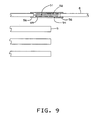
- Fig. 9 illustrates a flow-by vapour drain mounted in an opening in a disk cover mounting and retained between mylar tape and a particulate filter media enabling removal of the vapour entrapping media without exposing the enclosure to unfiltered air.
- Fig. 10 schematically illustrates vapour transport in a file with a vapour drain.
- Lubricant molecules also migrate from the disk surface 4 to the reservoir 3 as an air flow is induced by rotation on the disk 5.
- the maintenance of the correct film thickness of the lubricant is dependent on the existence of a "delta T", or a lower temperature, at the reservoir than at the rotating disks 5. Since there is no vehicle for the removal of contaminant vapours from the enclosure, the outgassing and other contaminants migrate to the reservoir and the disk surface and gradually accumulate in the reservoir until contaminants begin to reach the atmosphere coming from the reservoir outlet as well as from the sources of contamination.
- the reservoir delivers atmosphere that is effectively saturated with lubricant and is admixed with atmosphere passed through a chemical filter that captures substantially all vapours to provide a composite atmosphere with a lube relative vapour pressure that is stabilized at a relative pressure to maintain a partial molecular layer on the disk surface.
- Fig. 2 schematically illustrates the steady state vapour transport lubrication system wherein there is not only a reservoir 3 and disk surface 4, but also a vapour drain 6. Once again air passing through reservoir 3 emerges saturated with lube from within the reservoir.
- the vapour drain is a chemical filter that traps vapours and has an air flow which emerges with an organic vapour pressure that is substantially zero.
- the composite atmosphere supplied from the reservoir 3 and the vapour drain 6 is less than saturated and the system is not therefore dependent upon maintenance of a reduced temperature at the reservoir.
- the vapour drain essentially permanently entraps vapours in the air passing therethrough. Contaminant vapours as well as lubricant vapours are trapped. This gradually depletes the lubricant, but it also maintains the atmosphere and the disk surface almost contaminant free. It is also important that the lubricant supply in the reservoir not be depleted during the life of the disk drive.
- the reservoir capacity and the capability of the vapour drain to capture vapours are selected to achieve this result.
- Fig. 10 is a schematic concerning vapours inside a disk file. This shows a density of vapour in the file atmosphere 71, a disk 72, a file component 73 and a vapour drain 74. Into the atmosphere 71, the component 73 supplies vapour density. The surface of the disk 72 develops a coating whose thickness depends on the relative vapour density in the file atmosphere 71 at the disk surface. From the atmosphere 71, a significant part of the vapour density is steadily removed by the vapour drain 74.
- the density of vapour reaches a steady state. This is a dynamic balance between the rate that the component 73 supplies vapour density, and the rate that the vapour drain 74 removes vapour density.
- the relative vapour density is determined mainly by the aerodynamics, convection and diffusion. Also the relative vapour density is largely independent of chemical equilibrium parameters such as file temperature.
- the steady state is particularly simple. In some cases, the time constants are hours for the disk 72RC, many years for the component vapour source 73RC, many years for the vapour drain 74RC.
- vapour drain 74 can be applied to lubricant vapour supplied by a lubricant reservoir 73B, and removed by a vapour drain 74.
- the goal is to achieve 50% to 80% relative density of lubricant vapour (compared to the saturation density at the disk temperature). Therefore the vapour drain 74 should match the lubricant reservoir 73B.
- This provides a controlled relative vapour density which is largely independent of temperature gradient or overall temperature. This contrasts with US patent 4,789,913, that teaches a vapour replenishment system that depends on a temperature gradient to control the relative vapour density of lubricant.
- Some files have both significant outgassed contamination and vapour lubrication. It is desirable to greatly reduce the outgassed contamination, and to simultaneously achieve .50% to 80% relative density of lubrication vapour. To achieve this requires some parameterization.
- a vapour source parameterize its rate as the equivalent volume per unit time of saturated vapour added to a file atmosphere with initially zero vapour density.
- a vapour drain parameterize its rate as the equivalent volume per time of saturated vapour drained from a file atmosphere with initially saturated vapour density. In some cases, these rates equal the rate that air flows through the vapour source or vapour drain. (Implicitly, these parameterizations might depend on the vapour material. In many cases, these equivalent rates are dominated by convection aerodynamics. For various vapour materials, this depends on the vapour diffusivity, hence on the molecular weight of the vapour. Thus if outgassed contamination and lubricant have similar molecular weights, then the equivalent rate is independent of the vapour material.)
- vapour drain Another function for a vapour drain is to accumulate a sample of vapours for subsequent chemical testing. This favors a reversible absorber. First operate the file for some time with a reversible absorber. Later remove the absorber. In a laboratory, this can be heated to recover the sample for chemical testing. An alternative is to use a solvent to extract the sample. Below we describe structures to facilitate this chemical testing function.
- vapour drain Another modification is to design the vapour drain to have a greater initial capacity followed by a diminished adsorption capability.
- the outgassing contamination and other contaminant sources are more prolific, whereas following the initial period of operation the generation of contaminants stabilizes at significantly lower levels.
- This bilevel capability can be achieved by limiting the filtering capacity of the filter such that the initial capacity is significant while the later more restricted capacity supplies a longer term lower filtering capability that generally parallels the rate of contaminant generation.
- the HDA is a substantially sealed enclosure surrounding the transducer heads and rotating data storage disks.
- a breather filter 20 is provided and positioned to access the enclosed atmosphere at a location of low pressure. This filter 20 is provided to compensate for atmospheric and thermally induced temperature changes. By being located at a low pressure location it is assured that any leakage location is at a higher pressure such that leakage is out of the enclosure and that makeup air is filtered. Thus, no unfiltered air enters the enclosure.
- the breather filter is commonly provided with an extended length diffusion passage to prevent or limit the introduction of vapour contamination.
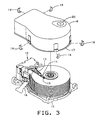
- Fig. 4 shows a file, with the cover partially broken away, which includes a steady state lubricant vapour transport system.
- a reservoir 3 is secured to the inner surface of the cover 8, has an air entrance 22 and an exit opening 23 to permit an air flow induced by rotation of disk 5 to pass therethrough.
- Another flow of air induced by disk rotation is partitioned with one portion directed through the recirculating particulate filter 24 and another portion directed through the vapour drain 25.
- Fig. 6 illustrates a further embodiment showing a disk drive with the cover 8 partially broken away wherein the lubricant reservoir and the vapour drain are formed as parallel arcuate paths in a single assembly.
- the reservoir-vapour drain assembly upper surface 33 is adhered to the cover inner surface in a position that is in the air flow induced by disk rotation.
- the reservoir-vapour drain assembly includes one arcuate channel 31 that houses the lubricant source or reservoir and the other, adjoining arcuate channel 32 provides the vapour drain.
- the rotating disk 5 induces an air flow from the entry openings 22 to the outlet openings 23. Since both reservoir 31 and vapour drain 32 are in a common air flow path, the balance between lubricant vapour bearing air and vapour depleted filtered air is easier to achieve in addition to the recognized economy achieved by fabricating both functional elements as a single device.
- vapour drain Since the essence of the vapour drain is vapour control, the concept is also applicable to drives that do not use vapour transport lubrication systems. Disk surfaces having a nonselective affinity for organic vapours are subject to the accumulation of such contaminants which emanate from such sources as material outgassing and bearing lubricants. In particular, drives including disks with bonded lubricants are benefited by the vapour scavenging capabilities of a vapour drain. This contamination control function is useful regardless of the lubrication system, which might be a bonded lubricant, a single application liquid lubricant, vapour replenished lubricant, or other lubrication systems.
- Fig. 8 illustrates an embodiment wherein a vapour drain is used in the form of a flow-by chemical absorber or adsorber which is bonded to the cover 8 and positioned in the path of air circulation induced by rotation of the disks 5.
- the mylar or polycarbonate backing layer 41 is bonded to the cover 8 inner surface 42.
- An activated carbon chemical filter 43 is retained by a HEPA particulate media which is bonded to the backing along its margins 46 either by an adhesive or ultra sonic welding.
- FIG. 9 Another embodiment of a vapour drain used for contaminant entrapment is shown in Fig. 9.
- the vapour drain is placed in an opening 49 in the cover 8.
- the exterior is sealed by mylar tape 52 which is bonded to the exterior surface of cover 8 along the marginal edge surfaces of the opening 49.
- the activated carbon vapour drain element 51 is in the cover opening and retained by a HEPA particulate media 54 which is continuously bonded by adhesive about its margins 56 to the inner surface 42 of cover 8.
- the vapor drain is fabricated as an assembly which is subsequently attached to the drive cover. If the mylar tape at the outer side of the vapour drain is removed, the activated carbon element 51 can be removed and even replaced without exposing the head-disk assembly within the enclosure to unfiltered air.
- This embodiment can be utilized either as a vapour drain for removing contaminants from the enclosure or as a sampling device which permits the filter to be removed so that entrapped contaminants can subsequently be analyzed.
- the vapour drain has been shown in this description as a recirculating type chemical absorber or adsorber for entrapping chemical vapours. This is the preferred embodiment.
- the same result could be obtained by using a controlled leak that permits a predetermined rate of loss of vapour to the atmosphere outside the enclosure. In this application it would be likewise necessary to limit vapour depletion to a rate that would not cause the vapour from the lubricant reservoir to be exhausted during the useful life of the device.
- lubricant vapour and contaminant vapours would be allowed to escape from the enclosure and be replaced by lubricant vapours from the reservoir.
- vapour drain has been described in terms of a magnetic disk memory. Nevertheless it is more widely applicable.
- a vapour drain can control vapours in an optical memories using "near field optics", which have heads that operate very close to a moving disk.
- a vapour drain can control vapours inside a Scanning Tunneling Microscope (STM), an Atomic Force Microscope (AFM), and other devices that have a head moving ultra-close to an ultra-smooth surface.
- STM Scanning Tunneling Microscope
- AFM Atomic Force Microscope
- a vapour drain is applicable to a memory device based on the STM microscope or any of these other devices.
Landscapes
- Manufacturing Of Magnetic Record Carriers (AREA)
- Magnetic Record Carriers (AREA)
- Supporting Of Heads In Record-Carrier Devices (AREA)
Applications Claiming Priority (2)
| Application Number | Priority Date | Filing Date | Title |
|---|---|---|---|
| US53526990A | 1990-05-24 | 1990-05-24 | |
| US535269 | 1990-05-24 |
Publications (2)
| Publication Number | Publication Date |
|---|---|
| EP0458528A1 true EP0458528A1 (fr) | 1991-11-27 |
| EP0458528B1 EP0458528B1 (fr) | 1995-12-27 |
Family
ID=24133514
Family Applications (1)
| Application Number | Title | Priority Date | Filing Date |
|---|---|---|---|
| EP91304421A Expired - Lifetime EP0458528B1 (fr) | 1990-05-24 | 1991-05-16 | Dispositif de stockage de données avec système de contrÔle de la pression de vapeur |
Country Status (3)
| Country | Link |
|---|---|
| EP (1) | EP0458528B1 (fr) |
| JP (1) | JP2803688B2 (fr) |
| DE (1) | DE69115755T2 (fr) |
Cited By (8)
| Publication number | Priority date | Publication date | Assignee | Title |
|---|---|---|---|---|
| US5346518A (en) * | 1993-03-23 | 1994-09-13 | International Business Machines Corporation | Vapor drain system |
| EP0738417A4 (fr) * | 1992-11-13 | 1996-03-15 | Maxtor Corp | Filtre a air et systeme de circulation d'air pour unite de disque dur |
| WO1996014637A1 (fr) * | 1994-11-08 | 1996-05-17 | Conner Peripherals, Inc. | Unite de disques equipee d'un tampon de diffusion du milieu ambiant en plusieurs etapes |
| WO1998041989A1 (fr) * | 1997-03-17 | 1998-09-24 | Donaldson Company, Inc. | Structure adsorbante et procede |
| US6143058A (en) * | 1997-03-17 | 2000-11-07 | Donaldson Company, Inc. | Adsorbent construction and method |
| US6146446A (en) * | 1998-10-08 | 2000-11-14 | Donaldson Company, Inc. | Filter assembly with shaped adsorbent article; and devices and methods of use |
| US6168651B1 (en) | 1998-10-08 | 2001-01-02 | Donaldson Company, Inc. | Filter assembly with shaped adsorbent article; and devices and methods of use |
| US6940686B2 (en) * | 1999-12-09 | 2005-09-06 | Matsushita Electric Industrial Co., Ltd. | Magnetic recording and reproducing device |
Citations (2)
| Publication number | Priority date | Publication date | Assignee | Title |
|---|---|---|---|---|
| EP0127444A1 (fr) * | 1983-05-26 | 1984-12-05 | Fujitsu Limited | Disques magnétiques recouverts d'un film lubrifiant |
| US4789913A (en) * | 1987-08-03 | 1988-12-06 | International Business Machines Corporation | Method and apparatus for lubricating a magnetic disk continuously in a recording file |
Family Cites Families (5)
| Publication number | Priority date | Publication date | Assignee | Title |
|---|---|---|---|---|
| JPS55157170A (en) * | 1979-05-21 | 1980-12-06 | Nippon Telegr & Teleph Corp <Ntt> | Magnetic storage device |
| JPS592273A (ja) * | 1982-06-25 | 1984-01-07 | Fujitsu Ltd | 磁気デイスク装置 |
| JPS59221873A (ja) * | 1983-05-30 | 1984-12-13 | Fujitsu Ltd | 磁気デイスク表面の潤滑膜安定化法 |
| JPS62279586A (ja) * | 1986-05-28 | 1987-12-04 | Alps Electric Co Ltd | 磁気デイスク駆動装置 |
| JPH01199389A (ja) * | 1987-10-01 | 1989-08-10 | Mitsubishi Electric Corp | 磁気ディスク装置および結露防止容器 |
-
1991
- 1991-04-24 JP JP3093881A patent/JP2803688B2/ja not_active Expired - Lifetime
- 1991-05-16 EP EP91304421A patent/EP0458528B1/fr not_active Expired - Lifetime
- 1991-05-16 DE DE1991615755 patent/DE69115755T2/de not_active Expired - Fee Related
Patent Citations (2)
| Publication number | Priority date | Publication date | Assignee | Title |
|---|---|---|---|---|
| EP0127444A1 (fr) * | 1983-05-26 | 1984-12-05 | Fujitsu Limited | Disques magnétiques recouverts d'un film lubrifiant |
| US4789913A (en) * | 1987-08-03 | 1988-12-06 | International Business Machines Corporation | Method and apparatus for lubricating a magnetic disk continuously in a recording file |
Non-Patent Citations (7)
| Title |
|---|
| PATENT ABSTRACTS OF JAPAN vol. 10, no. 348 (P-519) 22 November 1986, & JP-A-61 148691 (FUJITSU LTD) 07 July 1986, * |
| PATENT ABSTRACTS OF JAPAN vol. 10, no. 84 (P-442)(2141) 03 April 1986, & JP-A-60 219695 (NIPPON DENSHIN DENWA KOSHA) 02 November 1985, * |
| PATENT ABSTRACTS OF JAPAN vol. 12, no. 34 (P-662) 02 February 1988, & JP-A-62 184685 (NIPPON TELEGR & TELEPH CORP) 13 August 1987, * |
| PATENT ABSTRACTS OF JAPAN vol. 13, no. 566 (P-976) 15 December 1989, & JP-A-01 236423 (VICTOR CO OF JAPAN LTD) 21 September 1989, * |
| PATENT ABSTRACTS OF JAPAN vol. 14, no. 207 (P-1043) 26 April 1990, & JP-A-02 046586 (IBARAKI NIPPON DENKI KK) 15 February 1990, * |
| PATENT ABSTRACTS OF JAPAN vol. 24, no. 490 (P-1122) 25 October 1990 & JP-A-02199691 (NEC CORP) 08 August 1990 * |
| PATENT ABSTRACTS OF JAPAN vol. 9, no. 090 (P-350) 19 April 1985, & JP-A-59 218633 (FUJITSU KK) 08 December 1984, * |
Cited By (10)
| Publication number | Priority date | Publication date | Assignee | Title |
|---|---|---|---|---|
| EP0738417A4 (fr) * | 1992-11-13 | 1996-03-15 | Maxtor Corp | Filtre a air et systeme de circulation d'air pour unite de disque dur |
| US5346518A (en) * | 1993-03-23 | 1994-09-13 | International Business Machines Corporation | Vapor drain system |
| WO1996014637A1 (fr) * | 1994-11-08 | 1996-05-17 | Conner Peripherals, Inc. | Unite de disques equipee d'un tampon de diffusion du milieu ambiant en plusieurs etapes |
| WO1998041989A1 (fr) * | 1997-03-17 | 1998-09-24 | Donaldson Company, Inc. | Structure adsorbante et procede |
| US5876487A (en) * | 1997-03-17 | 1999-03-02 | Donaldson Company, Inc. | Adsorbent construction; and, method |
| US6143058A (en) * | 1997-03-17 | 2000-11-07 | Donaldson Company, Inc. | Adsorbent construction and method |
| US6146446A (en) * | 1998-10-08 | 2000-11-14 | Donaldson Company, Inc. | Filter assembly with shaped adsorbent article; and devices and methods of use |
| US6168651B1 (en) | 1998-10-08 | 2001-01-02 | Donaldson Company, Inc. | Filter assembly with shaped adsorbent article; and devices and methods of use |
| US6726745B2 (en) | 1998-10-08 | 2004-04-27 | Donaldson Company, Inc. | Filter assembly with shaped adsorbent article; and devices and methods of use |
| US6940686B2 (en) * | 1999-12-09 | 2005-09-06 | Matsushita Electric Industrial Co., Ltd. | Magnetic recording and reproducing device |
Also Published As
| Publication number | Publication date |
|---|---|
| JPH05342841A (ja) | 1993-12-24 |
| DE69115755T2 (de) | 1996-07-11 |
| JP2803688B2 (ja) | 1998-09-24 |
| DE69115755D1 (de) | 1996-02-08 |
| EP0458528B1 (fr) | 1995-12-27 |
Similar Documents
| Publication | Publication Date | Title |
|---|---|---|
| US5229899A (en) | Apparatus and method for controlling vapor phase within an enclosure | |
| US5447695A (en) | Chemical breather filter assembly | |
| US7388731B1 (en) | Hard disk drive recirculation air filter | |
| EP0458528B1 (fr) | Dispositif de stockage de données avec système de contrÔle de la pression de vapeur | |
| US5742449A (en) | Near contact magnetic recording using a liquid lubricant bearing to separate media and transducer | |
| US10134447B2 (en) | Humidity control for enclosure | |
| US5734521A (en) | Moisture-absorbent element for disk drives | |
| US9230608B2 (en) | Filter element for disc drive enclosure | |
| US20060032371A1 (en) | Adsorbent breather filter | |
| US8867164B2 (en) | Magnetic storage device with humidity control device incorporating a differentially permeable membrane | |
| US8885289B2 (en) | Magnetic storage device with multi-functional component for controlling chemical and water vapor therein | |
| WO2001022422A1 (fr) | Ensemble a filtre multifonctionnel rigide | |
| US9613658B2 (en) | Contamination reduction head for media | |
| US6972927B2 (en) | Flanged breather filter cartridge with an integrated diffusion path | |
| US8861127B2 (en) | Magnetic storage device with dynamic humidity control system to mitigate water vapor transients | |
| US9202504B2 (en) | Producing a magnetic disk device | |
| US7815715B2 (en) | Mounting configuration for a filtration canister | |
| US5680273A (en) | Method and apparatus employing system for recirculating liquid in a controlled enviroment | |
| US7466514B2 (en) | Control system to regulate the concentration of vapor in a hard disk drive | |
| US6356407B1 (en) | System and process for reducing contamination in internal disc drive environment | |
| WO2010036351A1 (fr) | Construction de filtre améliorée pour retirer des polluants d'une enceinte | |
| Fowler et al. | Protecting the head/disk interface from the chemical environment with disk drive filtration | |
| WO2007005084A2 (fr) | Construction de filtre amelioree servant a retirer des contaminants d'un boitier | |
| US20060132975A1 (en) | Humidity control in a removable data cartridge | |
| HK1026976B (en) | Disk drive with flow-by chemical breather filter |
Legal Events
| Date | Code | Title | Description |
|---|---|---|---|
| PUAI | Public reference made under article 153(3) epc to a published international application that has entered the european phase |
Free format text: ORIGINAL CODE: 0009012 |
|
| AK | Designated contracting states |
Kind code of ref document: A1 Designated state(s): DE FR GB |
|
| 17P | Request for examination filed |
Effective date: 19911219 |
|
| 17Q | First examination report despatched |
Effective date: 19940803 |
|
| GRAA | (expected) grant |
Free format text: ORIGINAL CODE: 0009210 |
|
| AK | Designated contracting states |
Kind code of ref document: B1 Designated state(s): DE FR GB |
|
| REF | Corresponds to: |
Ref document number: 69115755 Country of ref document: DE Date of ref document: 19960208 |
|
| ET | Fr: translation filed | ||
| PG25 | Lapsed in a contracting state [announced via postgrant information from national office to epo] |
Ref country code: GB Effective date: 19960516 |
|
| PLBE | No opposition filed within time limit |
Free format text: ORIGINAL CODE: 0009261 |
|
| STAA | Information on the status of an ep patent application or granted ep patent |
Free format text: STATUS: NO OPPOSITION FILED WITHIN TIME LIMIT |
|
| 26N | No opposition filed | ||
| GBPC | Gb: european patent ceased through non-payment of renewal fee |
Effective date: 19960516 |
|
| PG25 | Lapsed in a contracting state [announced via postgrant information from national office to epo] |
Ref country code: FR Effective date: 19970131 |
|
| PG25 | Lapsed in a contracting state [announced via postgrant information from national office to epo] |
Ref country code: DE Effective date: 19970201 |
|
| REG | Reference to a national code |
Ref country code: FR Ref legal event code: ST |