EP0458560B1 - Elément de protection contre la chaleur - Google Patents
Elément de protection contre la chaleur Download PDFInfo
- Publication number
- EP0458560B1 EP0458560B1 EP91304525A EP91304525A EP0458560B1 EP 0458560 B1 EP0458560 B1 EP 0458560B1 EP 91304525 A EP91304525 A EP 91304525A EP 91304525 A EP91304525 A EP 91304525A EP 0458560 B1 EP0458560 B1 EP 0458560B1
- Authority
- EP
- European Patent Office
- Prior art keywords
- cooling
- heat
- layer
- refractory
- water
- Prior art date
- Legal status (The legal status is an assumption and is not a legal conclusion. Google has not performed a legal analysis and makes no representation as to the accuracy of the status listed.)
- Expired - Lifetime
Links
- 238000001816 cooling Methods 0.000 claims description 42
- 239000000110 cooling liquid Substances 0.000 claims description 29
- 239000007788 liquid Substances 0.000 claims description 8
- 239000011810 insulating material Substances 0.000 claims description 2
- XLYOFNOQVPJJNP-UHFFFAOYSA-N water Substances O XLYOFNOQVPJJNP-UHFFFAOYSA-N 0.000 description 35
- 239000004744 fabric Substances 0.000 description 11
- VYPSYNLAJGMNEJ-UHFFFAOYSA-N Silicium dioxide Chemical compound O=[Si]=O VYPSYNLAJGMNEJ-UHFFFAOYSA-N 0.000 description 8
- 238000003860 storage Methods 0.000 description 6
- 239000000463 material Substances 0.000 description 5
- 239000000919 ceramic Substances 0.000 description 4
- 238000009826 distribution Methods 0.000 description 4
- 239000000377 silicon dioxide Substances 0.000 description 4
- 239000004411 aluminium Substances 0.000 description 3
- 229910052782 aluminium Inorganic materials 0.000 description 3
- XAGFODPZIPBFFR-UHFFFAOYSA-N aluminium Chemical compound [Al] XAGFODPZIPBFFR-UHFFFAOYSA-N 0.000 description 3
- 230000005540 biological transmission Effects 0.000 description 3
- 238000001704 evaporation Methods 0.000 description 3
- 229910001220 stainless steel Inorganic materials 0.000 description 3
- 239000010935 stainless steel Substances 0.000 description 3
- RYGMFSIKBFXOCR-UHFFFAOYSA-N Copper Chemical compound [Cu] RYGMFSIKBFXOCR-UHFFFAOYSA-N 0.000 description 2
- WYTGDNHDOZPMIW-RCBQFDQVSA-N alstonine Natural products C1=CC2=C3C=CC=CC3=NC2=C2N1C[C@H]1[C@H](C)OC=C(C(=O)OC)[C@H]1C2 WYTGDNHDOZPMIW-RCBQFDQVSA-N 0.000 description 2
- 230000015556 catabolic process Effects 0.000 description 2
- 239000002131 composite material Substances 0.000 description 2
- 229910052802 copper Inorganic materials 0.000 description 2
- 239000010949 copper Substances 0.000 description 2
- 238000006731 degradation reaction Methods 0.000 description 2
- 230000008020 evaporation Effects 0.000 description 2
- 239000000284 extract Substances 0.000 description 2
- 239000000835 fiber Substances 0.000 description 2
- 238000004079 fireproofing Methods 0.000 description 2
- 238000004519 manufacturing process Methods 0.000 description 2
- 239000012466 permeate Substances 0.000 description 2
- 239000011148 porous material Substances 0.000 description 2
- 239000000047 product Substances 0.000 description 2
- 230000001681 protective effect Effects 0.000 description 2
- 229920000271 Kevlar® Polymers 0.000 description 1
- 239000004677 Nylon Substances 0.000 description 1
- 229920006362 Teflon® Polymers 0.000 description 1
- 230000004888 barrier function Effects 0.000 description 1
- 229910052681 coesite Inorganic materials 0.000 description 1
- 230000000295 complement effect Effects 0.000 description 1
- 229910052906 cristobalite Inorganic materials 0.000 description 1
- 230000000694 effects Effects 0.000 description 1
- 230000009970 fire resistant effect Effects 0.000 description 1
- 239000004761 kevlar Substances 0.000 description 1
- 239000002184 metal Substances 0.000 description 1
- 229910052751 metal Inorganic materials 0.000 description 1
- 239000007769 metal material Substances 0.000 description 1
- 229920001778 nylon Polymers 0.000 description 1
- 238000005192 partition Methods 0.000 description 1
- 230000035515 penetration Effects 0.000 description 1
- 230000002265 prevention Effects 0.000 description 1
- 229910052710 silicon Inorganic materials 0.000 description 1
- 239000010703 silicon Substances 0.000 description 1
- 235000012239 silicon dioxide Nutrition 0.000 description 1
- 239000000779 smoke Substances 0.000 description 1
- 125000006850 spacer group Chemical group 0.000 description 1
- 229910052682 stishovite Inorganic materials 0.000 description 1
- 239000008400 supply water Substances 0.000 description 1
- 229910052905 tridymite Inorganic materials 0.000 description 1
- 238000009941 weaving Methods 0.000 description 1
- 238000009736 wetting Methods 0.000 description 1
- 238000004804 winding Methods 0.000 description 1
Images






Classifications
-
- E—FIXED CONSTRUCTIONS
- E04—BUILDING
- E04B—GENERAL BUILDING CONSTRUCTIONS; WALLS, e.g. PARTITIONS; ROOFS; FLOORS; CEILINGS; INSULATION OR OTHER PROTECTION OF BUILDINGS
- E04B1/00—Constructions in general; Structures which are not restricted either to walls, e.g. partitions, or floors or ceilings or roofs
- E04B1/62—Insulation or other protection; Elements or use of specified material therefor
- E04B1/92—Protection against other undesired influences or dangers
- E04B1/94—Protection against other undesired influences or dangers against fire
- E04B1/941—Building elements specially adapted therefor
- E04B1/942—Building elements specially adapted therefor slab-shaped
-
- Y—GENERAL TAGGING OF NEW TECHNOLOGICAL DEVELOPMENTS; GENERAL TAGGING OF CROSS-SECTIONAL TECHNOLOGIES SPANNING OVER SEVERAL SECTIONS OF THE IPC; TECHNICAL SUBJECTS COVERED BY FORMER USPC CROSS-REFERENCE ART COLLECTIONS [XRACs] AND DIGESTS
- Y10—TECHNICAL SUBJECTS COVERED BY FORMER USPC
- Y10S—TECHNICAL SUBJECTS COVERED BY FORMER USPC CROSS-REFERENCE ART COLLECTIONS [XRACs] AND DIGESTS
- Y10S165/00—Heat exchange
- Y10S165/907—Porous
-
- Y—GENERAL TAGGING OF NEW TECHNOLOGICAL DEVELOPMENTS; GENERAL TAGGING OF CROSS-SECTIONAL TECHNOLOGIES SPANNING OVER SEVERAL SECTIONS OF THE IPC; TECHNICAL SUBJECTS COVERED BY FORMER USPC CROSS-REFERENCE ART COLLECTIONS [XRACs] AND DIGESTS
- Y10—TECHNICAL SUBJECTS COVERED BY FORMER USPC
- Y10S—TECHNICAL SUBJECTS COVERED BY FORMER USPC CROSS-REFERENCE ART COLLECTIONS [XRACs] AND DIGESTS
- Y10S165/00—Heat exchange
- Y10S165/911—Vaporization
Definitions
- the present invention relates to a heat protection or refractory element for fire-proofing or heat-shielding purposes of the type referred to in the precharacterising portion of Claim 1.
- a building or the like may be fire-proofed by using refractory interior and exterior members and/or heat-insulating members between interior and exterior portions of the building.
- US-A-4301631 on which the precharacterising portion of Claim 1 is based, discloses a fire protective jacket having an inner case 1 and an impermeable intermediate case 2.
- a water tank 6 positioned above the fire protective element has a plurality of small holes formed in its wall.
- a water pool case 8 which is spaced from the intermediate case 2 and together with an outer case 10, which is insulated with fibre plates 11, defines a space within which water may run down.
- the space defined by the intermediate case 2 and the water pool case 8 is divided into a plurality of compartments or passages by partitions 9.
- the upper edge of the water pool case 8 is below the level of the holes 7 and water is supplied to the water tank 6 through a water supply pipe 16.
- the space defined by the intermediate case 2 and the water pool case 8 fills with water and water is then discharged through a plurality of outlets 12 at the top of the water pool case 8 and flows down the fibre plates 11.
- the object of the present invention is to provide a heat protection element which can maintain the temperature at its surface at a predetermined level, even when there is a fire adjacent the outer surface, and which, when in the form of a panel, may be very simply fabricated.
- a heat protection element of the type referred to above is characterised in that the outer cooling layer is porous and that the means for transferring cooling liquid comprises pipework which communicates with the passages and is arranged to direct the cooling liquid to the outer porous layer.
- a liquid such as water
- the liquid may discharge into the porous layer at a single point but it is preferred that this occurs at a plurality of spaced points over the area of the porous layer. Due to the fact that the porous layer is maintained damp it is cooled by the evaporation which occurs caused by the heat incident on it from a fire or other intense heat source.
- the heat protection element in accordance with the invention thus acts as a thermal barrier and therefore also as a fire protection element.
- the intermediate layer may be metallic in which case the liquid passages in the cooling layer will be in thermal contact with it and extract heat from it. It is however preferred that the intermediate layer is made of refractory, heat-insulating material which may optionally be lined on one or both surfaces with metallic material.
- the liquid passages of the cooling layer may constitute the inner surface of the heat protection element or they may be covered by a metallic layer which serves to spread and equalise the thermal load.
- the heat protection element in accordance with the invention may be in the form of a rigid panel.
- the invention also embraces an enclosure, such as a lift or elevator, made of a plurality of such panels and in this event the liquid passages of the cooling layers will be connected either in parallel or in series to a liquid supply.
- the element in accordance with the invention may be in the form of a flexible sheet and in this case the sheet may be spread over products or other articles to protect them from degradation in the event of a fire.
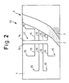
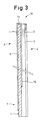
- an impermeable intermediate layer 1 which is fabricated from metal, such as a sheet of aluminium, stainless steel or the like, has outer and inner surfaces on which are disposed an outer, porous,, trickle cooling layer 4 and an inner heat-transmission cooling layer 8.
- the outer layer 4 comprises a soft porous member 2 such as a sheet of ceramic paper made of fibrous SiO2 and a hard porous member 3 such as a reinforced sheet of ceramic paper made of ceramic paper impregnated with silicon.
- a soft porous member 2 such as a sheet of ceramic paper made of fibrous SiO2
- a hard porous member 3 such as a reinforced sheet of ceramic paper made of ceramic paper impregnated with silicon.
- the inner layer 8 comprises a cooling pipework 7 which extends over substantially the entire area of the intermediate layer 1 and through which, in use, cooling liquid passes.
- the cooling pipework 7 has a main pipe section 5 extending along the base and along one side of the intermediate layer 1 and two serpentine sections 6 one of whose ends is connected to the main pipe section 5 and which is disposed in a zig-zag configuration on the inner surface of the intermediate layer 1.
- a cooling liquid supply means 10 in the form of a readily attachable joint or the like is connected to the inlet end 9 of the cooling pipework 7 at the lower end of the main pipe section 5.
- a cooling liquid distribution port means 12 in the form of a readily attachable joint or the like complementary to the supply means 10 is attached to the distribution end 11 of the cooling pipework 7 at the upper end of the main pipe section 5.
- An extension pipe 14 extends from the downstream end 13 of each serpentine section 6 over the upper side of the intermediate layer 1 to the rear surface thereof.
- Each extension pipe 14 is connected to a pipework 17 comprising a plurality of branched pipe sections 16 each having at its downstream end a cooling liquid trickling port 15 which is disposed between the intermediate layer 1 and the porous member 2.
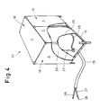
- the above refractory element is in the form of a panel 18 and a plurality of such panels 18 are joined to a frame 19 with the heat-transmission cooling layer 8 and the trickle cooling layer 4 being at the inside and outside, respectively, to form a refractory chamber 20, as illustrated in Figure 4.
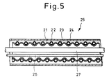
- a cooling liquid supply pipe 23 made of copper and having openings 22 is spirally wound around a flexible pipe 21, e.g. of stainless, corrugated material and is covered with a permeable refractory cloth 24 such as silica cloth, thereby providing a heat-shielded flexible composite pipe 25.
- the pipe 25 is connected at its one end to the bottom of the refractory chamber 20, and an electrical cable 26 and a cooling liquid supply pipe 27 which is different to the cooling liquid supply pipe 23, extend through the pipe 25 into the refractory chamber 20.
- the supply pipe 27 is connected to the supply port 10 of each refractory panel 18 (in this case, the distribution port 12 of each panel 18 is closed); alternatively, the cooling pipework 7 of each panel 18 is connected in series by connecting the ports 12 and 10 of adjacent panels 18 and the supply pipe 27 is connected to one of the supply port means 10 and only one of the distribution ports 12 is closed.
- Reference numeral 28 in Figure 1 denotes a cooling liquid and numeral 29 denotes an inner material covering the inner layer 8 of the panel 18.
- cooling liquid 28 is caused to flow through the supply pipes 23 and 27.
- this operation may be started manually by a person responsible for fire prevention.
- the cooling liquid 28 oozes through the openings 22 of the supply pipe 23 around the flexible pipe 21 and spreads through the permeable refractory cloth 24 by capillary action and wets the whole surface of the refractory cloth 24.
- the cooling liquid 28 evaporates from the cloth 24 to dissipate the heat received by the cloth 24 as latent heat, whereby the pipe 25 is protected from beat. Cooling liquid 28 is continuously supplied by capillary action to the cloth 24 from which it is evaporating.
- the refractory cloth 24 can thus be maintained in a constantly wetted state so long as the quantity of cooling liquid flowing through the supply pipe 23 is maintained at a suitable level.
- the cooling liquid 28 supplied through the supply pipe 27 flows into the supply port 10 of each refractory panel 18.
- the liquid 28 then flows through the main pipe section 5 and the serpentine pipe sections 16, thereby cooling the inner, heat-transmission cooling layer 8.
- the temperature is thus maintained at a constant level in the interior of the refractory panels 18 and thus in the refractory chamber 20.
- the cooling liquid 28 flows through the extension pipes 14 into the branched pipe sections 16 of the pipeline 17 and then trickles or oozes through the discharge ports 15.
- the discharged cooling liquid 28 permeates the porous materials 2 and 3 of the outer layer 4 by capillary action to wet its whole surface.
- cooling liquid 28 evaporates from the cooling layer 4 to dissipate the heat absorbed by the layer 4 as latent heat of evaporation and thereby prevents transmission of heat from the exterior into the interior of the refractory chamber 20.
- outer, intermediate and inner layers 4, 1 and 8 are integrally incorporated in the form of a refractory panel 18, and its fabrication is thus relatively simple.
- the temperature in the refractory chamber 20 can be maintained substantially constant.
- the refractory chamber 20 is adapted to be used as a shelter or a computer room.
- corridors in a building may be lined with such panels 18 so that it may be used as an emergency evacuation route in case of fire.
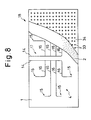
- the second embodiment illustrated in Figures 6 to 12 differs from the first embodiment in that the intermediate layer 1 comprises a refractory member 30 and impermeable members 31 such as a sheet of aluminium or stainless steel, the members 31 being bonded to opposite surfaces of the member 30 to form a sandwich and that the outer, trickle cooling layer 4 comprises a porous member 2 having an outer surface to which an exterior member 34 such as a sheet of stainless steel or a heat-resisting composite member with a large number of pores or small openings 33 is bonded with the interposition of spacers 35 so as to provide vapour passages 36.
- the intermediate layer 1 comprises a refractory member 30 and impermeable members 31 such as a sheet of aluminium or stainless steel, the members 31 being bonded to opposite surfaces of the member 30 to form a sandwich
- the outer, trickle cooling layer 4 comprises a porous member 2 having an outer surface to which an exterior member 34 such as a sheet of stainless steel or a heat-resisting composite member with a large number of pores or
- an interior member 29 is preliminarily bonded to the cooling pipework 7.
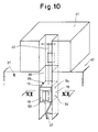
- Such panels 18 may be used to construct, for example, an elevator as shown in Figures 10 to 12.
- a vertically extending recess 38 is defined in an outer wall of a high building 37.
- An emergency elevator body 39 with walls made of or lined with the panels 18 is located within the recess 38 so as to be vertically movable. More specifically, the elevator body 39 is suspended by a wire 42 from an emergency exit room 41 constructed on the top 40 of the building 37.
- the wire 42 is securely joined at its upper end to the upper portion of the exit room 41 while the lower end thereof is wound around the winch drum 44 of a lift apparatus 43 securely connected to the top of the elevator body 39 so that when the wire 42 is wound or unwound by the winch drum 44, the elevator body 39 is lifted or lowered.
- the panels 18 are bonded to the elevator body 39 such that the heat-transmission cooling layers 8 define the interior walls of the elevator body 39 while the trickle cooling layers 4 define the exterior walls.
- an emergency air cylinder 45 capable of supplying air into the elevator body 39 and a water supply system or water tank 46 which is normally filled with a predetermined quantity of water and which is connected through valves (not shown) to the cooling pipework 7 of the panels 18 (see Figure 11).
- a fire-resistant cable 47 is connected to a predetermined position on the elevator body 39 and a water supply pipe 48 for supplying the water into the water tank 46, an electric power cable 49 for supplying power to the lift system 43 and an air supply pipe 50 for supplying air into the elevator body 39 independently of the air storage cylinder 45 extend through the refractory cable 47 from the exterior of the building 37 into the elevator body 39.
- the other end of the cable 47 is connected to, for example, a rescue trailer 51 as shown in Figure 12 which is equipped with a generator, a water pump, an air pump and which is parked near the building 37.
- Reference numeral 52 indicates an entrance door; 53, an exit door; and 54, guide rollers for preventing direct contact of the elevator body 39 with the building 37 during lifting or lowering of the body 39.
- the wire 42 is wound around the winch drum 44 of the lift system 43 to hold the elevator body 39 adjacent the emergency exit room 41.
- evacuees in the building 37 go up to the top 40 of the building 37 and then open the doors 52 and escape into the elevator body 39.
- the valve of the air storage cylinder 45 is opened to fill the interior of the elevator body 39 with fresh air so that the pressure therein rises slightly in excess of the atmospheric pressure, thereby preventing the intrusion of the smoke into the interior of the elevator body 39.
- the valve of the water storage cylinder 46 is opened to supply water to the cooling pipework 7 of the panels 18.
- each panel 18 cools the surface of the heat-transmission cooling layer 8 of the refractory panel 18 or the interior of the elevator body 39 and is introduced into the pipelines 17 and discharged or trickles through the discharge holes 15 so that it permeates into the porous member 2 of the trickle cooling layer 4, thereby wetting it.
- the other end of the refractory cable 47 is immediately connected to the rescue trailer 51 so as to supply electric power, water and air into the elevator body 39.
- the evacuees in the elevator body 39 operate the lift system 43 to lower the elevator body 39. Upon arrival on the ground, they open the exit doors 53 and get out of the elevator body 39.
- the elevator body 39 when the elevator body 39 is exposed to heat from the fire as it is lowered, the water evaporates through the surface of the porous members 2 of the refractory panels 18 to dissipate heat from the trickle cooling layer 4 as latent heat. As a result, penetration of heat from the exterior to the interior of the elevator body 39 is prevented. This effect is further promoted by the refractory intermediate layer 1 inwardly of the outer layer 4.
- the electric power is supplied from the rescue trailer 51 through the heat-resisting cable 47 in the second embodiment.
- a further lift system for winding or rewinding the wire 42 may be disposed on the top of the rescue room 41 to be energised by a power source in the building 37.
- the lift system 43 and this further lift system may be used alternatively or in combination.
- the reason why the air and water are supplied through the refractory cable 47 from the rescue trailer 51 is that if many people are to escape from the building 37, the elevator body 39 must be repeatedly lowered and lifted so that there is a risk of the air and water supplies from the air storage cylinder 45 and the water tank 46 being exhausted.
- the air and water may be directly supplied to the interior of the elevator body 39 from the rescue trailer 51 without providing the elevator body 39 with the air storage cylinder 45 and the water tank 46.
- the water pump on the rescue trailer 51 is used as the water supply to the elevator body 39.
- refractory cable 47 is wound and unwound by a winch drum which has connecting means for the water, electric power and air sources.
- FIG 13 illustrates another example of an elevator constructed from panels 18 according to the present invention.
- the inner walls of an elevator shaft 55 are constructed or lined with the panels 18 which are connected through a valve 57 to a water storage tank 56 provided on top of the building 37.
- the third embodiment illustrated in Figures 14 and 15 is substantially similar to the first and second embodiments except that the outer, trickle cooling layer 4 comprises the porous member 2, a wire retaining net 58 and a lattice 59.
- the fourth embodiment illustrated in Figure 16 is substantially similar to the first, second and third embodiments except that the inner, heat-transmission cooling layer 8 comprises a cooling liquid jacket 63 which has a corrugated plate 60 which defines cooling liquid passages 61 and 62 on both sides of the plate 60 and a plurality of pipes 64 which extend from the jacket 63 through the heat-insulating intermediate layer 1 to the porous member 2 to provide a trickle supply to the member 2 at a plurality of points distributed over its area.
- the inner, heat-transmission cooling layer 8 comprises a cooling liquid jacket 63 which has a corrugated plate 60 which defines cooling liquid passages 61 and 62 on both sides of the plate 60 and a plurality of pipes 64 which extend from the jacket 63 through the heat-insulating intermediate layer 1 to the porous member 2 to provide a trickle supply to the member 2 at a plurality of points distributed over its area.
- the heat-resistant element 65 in accordance with the invention is constructed in the form of a blanket.
- the intermediate layer 1 comprises a heat-resisting sheet 66 of flexible material, e.g. cloth made of the material sold under the Trade Mark Kevlar, on both surfaces of which aluminium is deposited.
- a heat-resisting sheet 66 of flexible material e.g. cloth made of the material sold under the Trade Mark Kevlar, on both surfaces of which aluminium is deposited.
- the cooling pipework 7 comprising nylon tubes, Teflon (trade mark) tubes, copper tubes or the like is sewed to the refractory sheet 66 and is covered with an interior member 73 which in turn is made of material substantially similar to that of the heat-resisting sheet 66, which components together constitute the heat-transmission cooling layer 8.
- the trickle cooling layer 4 comprises porous ceramic paper 67 sandwiched by silica cloth sheets 68 and 69, which are made by weaving silica fibres to form an integrated cloth-like body 70.
- Belts 71 and buckles 72 are attached to opposite sides of the refractory blanket 65.
- the fifth embodiment is substantially similar to the first to the fifth embodiments and also can be used in a similar manner.
Landscapes
- Engineering & Computer Science (AREA)
- Architecture (AREA)
- Physics & Mathematics (AREA)
- Electromagnetism (AREA)
- Civil Engineering (AREA)
- Structural Engineering (AREA)
- Building Environments (AREA)
Claims (4)
- Elément de protection contre la chaleur comportant une couche intermédiaire imperméable (1), une couche de refroidissement interne (8) avec des passages de liquide (5, 6, 7) à travers lesquels, en utilisation, un liquide de refroidissement s'écoule contigu à la surface interne de la couche intermédiaire, une couche de refroidissement externe (4) contiguë à la surface extérieure de la couche intermédiaire et des moyens (17) pour transférer le liquide de refroidissement à partir des passages de refroidissement (5, 6, 7) à la couche de refroidissement externe (4), caractérisé en ce que la couche de refroidissement externe (4) est poreuse et en ce que les moyens pour transférer le liquide de refroidissement comprennent une tuyauterie (17) qui communique avec les passages (5, 6, 7) et est disposée pour diriger le liquide de refroidissement vers la couche poreuse extérieure (4).
- Elément selon la revendication 1, caractérisé en ce que la couche intermédiaire (1) est constituée d'un matériau isolant de la chaleur réfractaire.
- Elément selon la revendication 1 ou la revendication 2, caractérisé en ce qu'il est sous la forme d'un panneau rigide (18).
- Elément selon la revendication 1 ou la revendication 2, caractérisé en ce qu'il est sous la forme d'une feuille souple (65).
Applications Claiming Priority (8)
| Application Number | Priority Date | Filing Date | Title |
|---|---|---|---|
| JP13056490A JP2841712B2 (ja) | 1990-05-21 | 1990-05-21 | 耐火パネル |
| JP13056390A JP2841711B2 (ja) | 1990-05-21 | 1990-05-21 | 耐火パネル |
| JP130565/90 | 1990-05-21 | ||
| JP130563/90 | 1990-05-21 | ||
| JP13056590A JPH0424030A (ja) | 1990-05-21 | 1990-05-21 | 耐火ブランケット |
| JP130564/90 | 1990-05-21 | ||
| JP267142/90 | 1990-10-04 | ||
| JP26714290A JPH04144895A (ja) | 1990-10-04 | 1990-10-04 | エレベータ |
Publications (3)
| Publication Number | Publication Date |
|---|---|
| EP0458560A2 EP0458560A2 (fr) | 1991-11-27 |
| EP0458560A3 EP0458560A3 (en) | 1992-06-24 |
| EP0458560B1 true EP0458560B1 (fr) | 1994-10-26 |
Family
ID=27471549
Family Applications (1)
| Application Number | Title | Priority Date | Filing Date |
|---|---|---|---|
| EP91304525A Expired - Lifetime EP0458560B1 (fr) | 1990-05-21 | 1991-05-20 | Elément de protection contre la chaleur |
Country Status (3)
| Country | Link |
|---|---|
| US (5) | US5329785A (fr) |
| EP (1) | EP0458560B1 (fr) |
| DE (1) | DE69104773T2 (fr) |
Cited By (1)
| Publication number | Priority date | Publication date | Assignee | Title |
|---|---|---|---|---|
| WO1998041285A1 (fr) * | 1997-03-19 | 1998-09-24 | Atle Nordvik | Element de protection thermique |
Families Citing this family (22)
| Publication number | Priority date | Publication date | Assignee | Title |
|---|---|---|---|---|
| EP0458560B1 (fr) * | 1990-05-21 | 1994-10-26 | Ishikawajima-Harima Jukogyo Kabushiki Kaisha | Elément de protection contre la chaleur |
| JP2697645B2 (ja) * | 1994-10-31 | 1998-01-14 | 日本電気株式会社 | 半導体装置の製造方法 |
| US5588303A (en) * | 1995-08-22 | 1996-12-31 | Parks; Jeffery S. | Armored vehicle surface cooling system |
| US6109338A (en) * | 1997-05-01 | 2000-08-29 | Oceaneering International, Inc. | Article comprising a garment or other textile structure for use in controlling body temperature |
| ATE203005T1 (de) * | 1998-01-26 | 2001-07-15 | Luigi Riva | Verfahren zur kühlung der luft in unterdachraume von gebäude |
| US5976594A (en) * | 1998-02-26 | 1999-11-02 | Lafollette; John | System and process for producing feed from food waste |
| DE19852724C2 (de) * | 1998-11-16 | 2002-10-31 | Lampertz Fab Org | Sicherheitsraum für informationstechnische Einrichtungen |
| DE19852927B4 (de) * | 1998-11-17 | 2004-05-27 | Otto Lampertz Gmbh & Co. Kg | Sicherheitsraum für informationstechnische Einrichtungen |
| US6148619A (en) * | 1999-08-17 | 2000-11-21 | Evans; Daniel J. | Method and apparatus for non-invasively freezing a content of a pipe |
| ES2163374B1 (es) * | 2000-05-04 | 2003-02-16 | Thertim S L | Disposicion de seguridad contra incendios aplicable para dilatar, demorar controlar y extinguir la accion del fuego mediante humectacion, teniendo el agua como elemento basico extintor. |
| WO2002067707A1 (fr) * | 2001-02-23 | 2002-09-06 | Seft Development Laboratory Co.,Ltd. | Vetement de refroidissement |
| US6718790B2 (en) * | 2001-08-07 | 2004-04-13 | Tetsuo Moriguchi | Cooling device, condenser, and air conditioning system |
| US20030145980A1 (en) * | 2002-02-04 | 2003-08-07 | Sinha Sumon Kumar | System and method for using a flexible composite surface for pressure-drop free heat transfer enhancement and flow drag reduction |
| US20060096207A1 (en) * | 2004-10-15 | 2006-05-11 | George Spais | Collar for increasing T-ratings and performance of firestop systems |
| DE102005023025A1 (de) * | 2005-05-13 | 2006-11-16 | Baret Finance Ag | Kühlsystem mit aktivierbarer, Superabsorber beinhaltender Umhüllung |
| SG173062A1 (en) * | 2009-01-20 | 2011-08-29 | Hoffmann La Roche | Cryogenic container |
| US20110042121A1 (en) * | 2009-08-21 | 2011-02-24 | Rogers Bernard I | Electrical cable protection block |
| GB2475562B (en) * | 2009-11-24 | 2015-11-11 | E W M Ltd | Appliance comprising a stove and a heat shield |
| EP2732223A2 (fr) * | 2011-07-15 | 2014-05-21 | Inuteq B.V. | Elément de refroidissement |
| US10704794B2 (en) | 2015-04-07 | 2020-07-07 | Brown University | Apparatus and method for passively cooling an interior |
| CN105963890A (zh) * | 2016-06-15 | 2016-09-28 | 张舒维 | 一种用于工业场合的智能消防系统 |
| CA3110861A1 (fr) | 2018-08-31 | 2020-03-05 | Techstyle Materials, Inc. | Systeme multifonctionnel pour gestion passive de chaleur et d'eau |
Family Cites Families (19)
| Publication number | Priority date | Publication date | Assignee | Title |
|---|---|---|---|---|
| US2941759A (en) * | 1957-01-14 | 1960-06-21 | Gen Dynamics Corp | Heat exchanger construction |
| US3138009A (en) * | 1957-04-17 | 1964-06-23 | Gen Electric | Transpiration cooling system |
| US3079765A (en) * | 1961-09-26 | 1963-03-05 | Litton Systems Inc | Cooling garment |
| US3090212A (en) * | 1961-09-27 | 1963-05-21 | Roger A Anderson | Sandwich panel construction |
| US3180111A (en) * | 1962-11-05 | 1965-04-27 | United Aircraft Corp | Combined insulating and cooling blanket |
| US3605412A (en) * | 1968-07-09 | 1971-09-20 | Bolkow Gmbh | Fluid cooled thrust nozzle for a rocket |
| US3866672A (en) * | 1971-07-16 | 1975-02-18 | F D Rich Housing Corp | Building |
| US3945432A (en) * | 1972-02-10 | 1976-03-23 | Robert Teudar Tamblyn | Air conditioning method and system |
| US4310926A (en) * | 1979-09-06 | 1982-01-19 | Jules Maroist | Fireproof suit |
| US4301631A (en) * | 1979-12-17 | 1981-11-24 | Michiji Tazaki | Water cooling jacket for protection from fire |
| US4616694A (en) * | 1984-10-22 | 1986-10-14 | Hsieh Shih Yung | Fireproof cabinet system for electronic equipment |
| US4775002A (en) * | 1985-05-14 | 1988-10-04 | Mitsui & Co., Ltd. | Delivering equipment having heat insulating function which is utilized in delivering articles such as food |
| JPH0787238B2 (ja) * | 1986-12-01 | 1995-09-20 | 三菱電機株式会社 | 半導体記憶装置 |
| DE3803534C1 (fr) * | 1988-02-05 | 1989-09-07 | Guenter Prof. Dr.-Ing. 7500 Karlsruhe De Ernst | |
| DE3805822A1 (de) * | 1988-02-25 | 1989-09-07 | Philips Patentverwaltung | Anordnung zum anpressen eines papierstapels gegen vereinzelungsrollen |
| JP2597337B2 (ja) * | 1988-10-03 | 1997-04-02 | 株式会社タナカホームズ | 床構造および床施工法 |
| JP2705813B2 (ja) * | 1988-11-10 | 1998-01-28 | オルガノ株式会社 | 活性炭の処理方法 |
| KR910012619A (ko) * | 1989-12-28 | 1991-08-08 | 강진구 | 공기 조화기 |
| EP0458560B1 (fr) * | 1990-05-21 | 1994-10-26 | Ishikawajima-Harima Jukogyo Kabushiki Kaisha | Elément de protection contre la chaleur |
-
1991
- 1991-05-20 EP EP91304525A patent/EP0458560B1/fr not_active Expired - Lifetime
- 1991-05-20 DE DE69104773T patent/DE69104773T2/de not_active Expired - Lifetime
-
1993
- 1993-06-08 US US08/073,619 patent/US5329785A/en not_active Expired - Lifetime
- 1993-08-26 US US08/111,910 patent/US5390729A/en not_active Expired - Fee Related
- 1993-08-26 US US08/111,889 patent/US5345995A/en not_active Expired - Lifetime
- 1993-08-26 US US08/111,944 patent/US5379610A/en not_active Expired - Lifetime
-
1994
- 1994-03-24 US US08/217,178 patent/US5421400A/en not_active Expired - Fee Related
Cited By (2)
| Publication number | Priority date | Publication date | Assignee | Title |
|---|---|---|---|---|
| WO1998041285A1 (fr) * | 1997-03-19 | 1998-09-24 | Atle Nordvik | Element de protection thermique |
| US6174588B1 (en) | 1997-03-19 | 2001-01-16 | Nordvik Atle Bjoern | Heat protection element |
Also Published As
| Publication number | Publication date |
|---|---|
| DE69104773T2 (de) | 1995-03-02 |
| US5390729A (en) | 1995-02-21 |
| DE69104773D1 (de) | 1994-12-01 |
| EP0458560A2 (fr) | 1991-11-27 |
| US5379610A (en) | 1995-01-10 |
| EP0458560A3 (en) | 1992-06-24 |
| US5345995A (en) | 1994-09-13 |
| US5329785A (en) | 1994-07-19 |
| US5421400A (en) | 1995-06-06 |
Similar Documents
| Publication | Publication Date | Title |
|---|---|---|
| EP0458560A2 (fr) | Elément de protection contre la chaleur | |
| US4616694A (en) | Fireproof cabinet system for electronic equipment | |
| US4294242A (en) | Survival system | |
| US5809699A (en) | Fire curtain | |
| US5572991A (en) | Air flush system for a firefighter's garment | |
| EP2038596B1 (fr) | Distillation cryogénique comportant un panneau isolant sous vide | |
| GB1591259A (en) | Fire resistant enclosures | |
| GB2058320A (en) | Double-walled tanks for low temperature liquids | |
| WO2007082559A1 (fr) | Matériau isolant comprenant un matériau à changement de phase (pcm) pour bâtiments | |
| KR101902153B1 (ko) | 접철식 대피공간 제공장치 | |
| ES2318895T3 (es) | Puerta de rellano para ascensor a prueba de fuego. | |
| KR20010013900A (ko) | 연소방지시트, 연소방지커버, 소화시트겸방재용피복 | |
| US6174588B1 (en) | Heat protection element | |
| US6874284B1 (en) | Fire safety unit | |
| US4902550A (en) | Laminated insulating material | |
| JPH09268852A (ja) | 建築用遮熱シャッタ− | |
| JPS622277B2 (fr) | ||
| JP2841712B2 (ja) | 耐火パネル | |
| JPS647175B2 (fr) | ||
| JPH08182147A (ja) | 橋りょう添架ケーブル管の耐火構造体 | |
| ITGE950097A1 (it) | Dispositivo per la coibentazione attiva e per la protezione antincendio. | |
| US4304082A (en) | Protective screen for improving the fire resistance of building structures | |
| RU2690805C1 (ru) | Переносное средство для предотвращения распространения и локализации пожара | |
| JP2841711B2 (ja) | 耐火パネル | |
| CN215106586U (zh) | 一种组装式防火钢结构 |
Legal Events
| Date | Code | Title | Description |
|---|---|---|---|
| PUAI | Public reference made under article 153(3) epc to a published international application that has entered the european phase |
Free format text: ORIGINAL CODE: 0009012 |
|
| AK | Designated contracting states |
Kind code of ref document: A2 Designated state(s): DE FR GB IT |
|
| PUAL | Search report despatched |
Free format text: ORIGINAL CODE: 0009013 |
|
| AK | Designated contracting states |
Kind code of ref document: A3 Designated state(s): DE FR GB IT |
|
| 17P | Request for examination filed |
Effective date: 19920821 |
|
| 17Q | First examination report despatched |
Effective date: 19931105 |
|
| GRAA | (expected) grant |
Free format text: ORIGINAL CODE: 0009210 |
|
| AK | Designated contracting states |
Kind code of ref document: B1 Designated state(s): DE FR GB IT |
|
| REF | Corresponds to: |
Ref document number: 69104773 Country of ref document: DE Date of ref document: 19941201 |
|
| ET | Fr: translation filed | ||
| ITF | It: translation for a ep patent filed | ||
| PLBE | No opposition filed within time limit |
Free format text: ORIGINAL CODE: 0009261 |
|
| STAA | Information on the status of an ep patent application or granted ep patent |
Free format text: STATUS: NO OPPOSITION FILED WITHIN TIME LIMIT |
|
| 26N | No opposition filed | ||
| REG | Reference to a national code |
Ref country code: GB Ref legal event code: IF02 |
|
| PGFP | Annual fee paid to national office [announced via postgrant information from national office to epo] |
Ref country code: GB Payment date: 20100329 Year of fee payment: 20 |
|
| PGFP | Annual fee paid to national office [announced via postgrant information from national office to epo] |
Ref country code: FR Payment date: 20100525 Year of fee payment: 20 |
|
| PGFP | Annual fee paid to national office [announced via postgrant information from national office to epo] |
Ref country code: IT Payment date: 20100522 Year of fee payment: 20 Ref country code: DE Payment date: 20100512 Year of fee payment: 20 |
|
| REG | Reference to a national code |
Ref country code: DE Ref legal event code: R071 Ref document number: 69104773 Country of ref document: DE |
|
| REG | Reference to a national code |
Ref country code: GB Ref legal event code: PE20 Expiry date: 20110519 |
|
| PG25 | Lapsed in a contracting state [announced via postgrant information from national office to epo] |
Ref country code: GB Free format text: LAPSE BECAUSE OF EXPIRATION OF PROTECTION Effective date: 20110519 |
|
| PG25 | Lapsed in a contracting state [announced via postgrant information from national office to epo] |
Ref country code: DE Free format text: LAPSE BECAUSE OF EXPIRATION OF PROTECTION Effective date: 20110521 |