EP0458630B1 - Reibschweissung - Google Patents
Reibschweissung Download PDFInfo
- Publication number
- EP0458630B1 EP0458630B1 EP91304660A EP91304660A EP0458630B1 EP 0458630 B1 EP0458630 B1 EP 0458630B1 EP 91304660 A EP91304660 A EP 91304660A EP 91304660 A EP91304660 A EP 91304660A EP 0458630 B1 EP0458630 B1 EP 0458630B1
- Authority
- EP
- European Patent Office
- Prior art keywords
- component
- jaw
- channel
- longitudinally
- blade
- Prior art date
- Legal status (The legal status is an assumption and is not a legal conclusion. Google has not performed a legal analysis and makes no representation as to the accuracy of the status listed.)
- Expired - Lifetime
Links
- 230000000694 effects Effects 0.000 claims description 3
- 230000000295 complement effect Effects 0.000 claims description 2
- 238000010438 heat treatment Methods 0.000 description 4
- 239000002184 metal Substances 0.000 description 4
- 238000004519 manufacturing process Methods 0.000 description 3
- 238000003466 welding Methods 0.000 description 3
- 230000003534 oscillatory effect Effects 0.000 description 2
- 230000000712 assembly Effects 0.000 description 1
- 238000000429 assembly Methods 0.000 description 1
- 238000010586 diagram Methods 0.000 description 1
- 239000012634 fragment Substances 0.000 description 1
- 238000003754 machining Methods 0.000 description 1
- 238000000034 method Methods 0.000 description 1
- 230000002093 peripheral effect Effects 0.000 description 1
- 230000002040 relaxant effect Effects 0.000 description 1
- 239000007787 solid Substances 0.000 description 1
- 239000000126 substance Substances 0.000 description 1
Images
Classifications
-
- B—PERFORMING OPERATIONS; TRANSPORTING
- B23—MACHINE TOOLS; METAL-WORKING NOT OTHERWISE PROVIDED FOR
- B23K—SOLDERING OR UNSOLDERING; WELDING; CLADDING OR PLATING BY SOLDERING OR WELDING; CUTTING BY APPLYING HEAT LOCALLY, e.g. FLAME CUTTING; WORKING BY LASER BEAM
- B23K20/00—Non-electric welding by applying impact or other pressure, with or without the application of heat, e.g. cladding or plating
- B23K20/12—Non-electric welding by applying impact or other pressure, with or without the application of heat, e.g. cladding or plating the heat being generated by friction; Friction welding
- B23K20/1205—Non-electric welding by applying impact or other pressure, with or without the application of heat, e.g. cladding or plating the heat being generated by friction; Friction welding using translation movement
-
- B—PERFORMING OPERATIONS; TRANSPORTING
- B23—MACHINE TOOLS; METAL-WORKING NOT OTHERWISE PROVIDED FOR
- B23K—SOLDERING OR UNSOLDERING; WELDING; CLADDING OR PLATING BY SOLDERING OR WELDING; CUTTING BY APPLYING HEAT LOCALLY, e.g. FLAME CUTTING; WORKING BY LASER BEAM
- B23K2101/00—Articles made by soldering, welding or cutting
- B23K2101/001—Turbines
Definitions
- the invention relates to apparatus for performing friction bonding operations.
- it concerns apparatus for performing a non-rotational frictional bonding operation.
- US-A-3,584,777 discloses a tailstock for feeding a workpiece in a rotary friction welding application.
- the work is firmly held in blocks which are biased together by hydraulic and/or spring means.
- the block pressure is temporarily relaxed when fresh work is fed into the rear of the tailstock from a hopper and delivery means.
- EP-A1-0,290,134 concerns the friction welding of a blade to a disk by rubbing the blade in an oscillatory manner in an arcuate path on the disk, and relates in particular to a linkage of pivots and levers whereby the oscillatory movement of the blade may be brought to a sudden stop at a precise location on the disk by bringing one pivot into alignment with another.
- a bladed disc comprises a disc or wheel on the periphery of which there is attached or carried a multiplicity of blades.
- the blades are attached to a disc or wheel by interlocking root fixtures.
- the blades are either formed integrally with the disc or are non-dismountably attached thereto.
- the present invention finds application for the manufacture or repair of assemblies in which the inter-blade spacing is very close and the blades may also be small. Such an example may be in the repair of a high pressure compressor bladed disc rotor.
- Small blades are also relatively fragile and may be easily damaged during a friction bonding operation which involves very large forces to produce the required frictional heating effects. Therefore, it is preferred to work with a blade blank or preform and to finish the blade to its final shape after bonding.
- a blade or blade preform is attached to the rim of a bladed disc in a non-rotational friction bonding operation.
- apparatus for linear friction bonding a first component defining a longitudinal direction to a second component, includes a generally C-shaped frame member having a pair of longitudinally extending limb members arranged either side of the first component and jaw pieces adapted to positively engage opposite sides of the first component, and is characterised in that each limb member is provided with a channel extending longitudinally from its distal end and facing the corresponding channel of the other limb member, each channel being shaped to have a tapering cross-section as it extends longitudinally from its respective distal end, and each jaw piece is adapted to slide longitudinally within and to cooperate with a respective channel so that when the jaw pieces move in the channels away from the distal ends of the limb members the jaw pieces tend to grip the first component more positively.
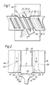
- a blade preform or blank 2 is bonded to the periphery of disc 4, a fragment of which is shown in the drawing, at a predetermined location.
- Figure 1 shows such a blade preform 2 clamped between jaw pieces 6,8 at the start of a bonding operation.
- the preform 2 consists of solid block of metal of appropriate shape and size. At the leading and trailing edge regions 10,12 a considerable amount of sacrificial metal is left by which the jaw pieces 6,8 grip the preform 2. The edges are formed with angled faces for engagement by the jaw pieces 6,8. In figure 1 the radially outer ends of preforms 2 are shown hatched for easier reference. After finishing of the blade airfoil shape these end faces form the blade tip faces.
- the jaw pieces 6,8 are moveably located in channels 24,26 in the inner faces of limbs 14,16 respectively of a C-shaped frame 18.
- the jaw pieces 6,8 have angled grip faces, V-shaped in plan to grip the complementary angled faces on the leading and trailing edges of the preform 2.
- At the apex of the angled faces relatively deep grooves 20,22 are cut into the jaw pieces to provide the angled faces with a degree of resilience in gripping the preform.
- the jaw pieces 6,8 are located, as mentioned above, in channels 24,26 formed in the inner faces of the frame limbs 14,16.
- the jaw pieces are slideable longitudinally in the channels 24,26 in the direction of arrows 28,30..
- Towards the distal end of each limb 14,16 the base of the channel and the abutting face of the respective jaw piece 6,8 are angled obliquely with respect to the longitudinal direction of movement 28,30. These angled surfaces converge towards the upper or closed part of the clamping frame so that by drawing the jaw pieces 6,8 upwardly in figure 2, in the direction of arrows 28,30, their grip on the blade preform 2 is tightened.
- the jaw pieces 6,8 may extend longitudinally in the directions of arrows 28,30 as shown in the drawings or may be attached to tensile members.
- the remote ends of the jaw piece extensions or the tensile members are connected to hydraulic tensioning means (not shown) which is energised to draw the jaw pieces upwardly to grip the preform.
- the clamping means may be released from the preform after a bonding operation by relaxing the tensioning force in the jaw pieces.
- the moveable clamping frame 18 also carries a ram 32 which bears against the tip face of blade preform 2 and applies the required upset force to effect bonding at the end of the frictional heating phase of the operation.
- the old or damaged blade is removed just above the peripheral surface 34 of the disc rim leaving a stub portion 36.
- the upper surface 38 of this stub is made flat and the foot of the replacement blade preform is bonded to it.
- the preform 2 is at least longer than the stub 36 due to the presence of the sacrificial gripping regions 10 and 12. It may be slightly wider also.
- the lower margin of the preform is therefore preferably chamfered so that lower surface 40 matches upper surface 38 of stub 36.
- the surface 40 may be made shaped for better control of the frictional heating phase.
- the clamping means containing the preform 2 is moved back and forth.
- Several directions of movement are available in the plane of the joint. The amplitude of this movement is small, generally only a few millimetres is required and is at a low frequency.
- the jaws of the clamping means are wider than the inter-blade spacing. Because of the resulting overlap the distance between the jaws must provide sufficient clearance for the chosen motion. The extra distance is easily provided for in the edge regions 10,12 on the preform 2. Thus, during the whole of a bonding operation clearance is maintained between the clamping means and adjacent blade tips.
- the jaw pieces 6,8 are preferably flush with the face of the clamping means. Where the blades are closely spaced the clearance distance must be maintained to avoid blade damage. It follows, therefore, that the edge regions 10,12 of a blade preform which are intended to be engaged by the clamping means must be removed after bonding and before another blade may be bonded at an adjacent location.
- a number of blade preforms may be bonded sequentially at locations sufficiently far apart.
- the minimum spacing is alternate locations.
- a whole BLISK could be manufactured, if desired, in this way by bonding blades at, say, alternate locations in a first operation, subsequently removing surplus metal and then bonding the remaining blades in a further operation.
- the preform or preforms are finished to final blade airfoil shape by a further manufacturing operation.
- Surplus metal including that upset during bonding is removed at this stage, for example, by electro-chemical machining.
Landscapes
- Engineering & Computer Science (AREA)
- Mechanical Engineering (AREA)
- Pressure Welding/Diffusion-Bonding (AREA)
- Turbine Rotor Nozzle Sealing (AREA)
Claims (4)
- Vorrichtung zum Verbinden eines ersten Bauteils (2), das eine Längsrichtung (28, 30) definiert, mit einem zweiten Bauteil (4) durch geradlinige Reibschweißung, wobei die Vorrichtung einen etwa C-förmigen Rahmenkörper (18) mit zwei in Längsrichtung verlaufenden Schenkeln (14, 16), die beiderseits des ersten Bauteils (2) angeordnet sind, und Backenstücke (6, 8) aufweist, die für ein Ergreifen des ersten Bauteils (2) an gegenüberliegenden Seiten ausgebildet sind, dadurch gekennzeichnet, daß jeder Schenkel (14, 16) mit einer von seinem distalen Ende aus längsverlaufenden Nut (24, 26) versehen ist, die der entsprechenden Nut (24, 26) des anderen Schenkels (14, 16) zugewandt ist, wobei jede Nut (24, 26) so gestaltet ist, daß sie einen über ihrem Längsverlauf von dem betreffenden distalen Ende aus sich verjüngenden Querschnitt hat, und daß jedes Backenstück (6, 8) gleitend längsverschiebbar mit der entsprechenden Nut (24, 26) zusammenwirkt, so daß, wenn die Backenstücke (6, 8) in den Nuten (24, 26) von den distalen Enden der Schenkel (14, 16) weg verschoben werden, die Backenstücke (6, 8) das erste Bauteil (2) fester ergreifen.
- Vorrichtung nach Anspruch 1, dadurch gekennzeichnet, daß jedes Backenstück (6, 8) mit einer abgewinkelten Griffläche versehen ist, die in der Draufsicht V-förmig ist, um eine entsprechend komplementär abgewinkelte Fläche des Bauteils (2) zu ergreifen.
- Vorrichtung nach Anspruch 2, dadurch gekennzeichnet, daß in jedem Backenstück (6, 8) am Scheitel der betreffenden abgewinkelten Griffläche eine Nut (20, 22) vorgesehen ist, um die abgewinkelte Griffläche mit einem gewissen Maß an Elastizität beim Ergreifen des ersten Bauteils (2) auszustatten, wenn das Backenstück (6, 8) sich in der betreffenden Nut (24, 26) verschiebt und mit deren Verjüngung zusammenwirkt.
- Vorrichtung nach einem der vorhergeheden Ansprüche, dadurch gekennzeichnet, daß der C-förmige Rahmenkörper (18) mit einem Stößel (32) versehen ist, der in Längsrichtung an dem ersten Bauteil (2) anlegbar ist, um eine erforderliche Kraft zur Bewirkung der Verschweißung zwischen dem ersten Bauteil (2) und dem zweiten Bauteil (4) zu bewirken.
Applications Claiming Priority (2)
| Application Number | Priority Date | Filing Date | Title |
|---|---|---|---|
| GB909011605A GB9011605D0 (en) | 1990-05-24 | 1990-05-24 | Friction bonding |
| GB9011605 | 1990-05-24 |
Publications (2)
| Publication Number | Publication Date |
|---|---|
| EP0458630A1 EP0458630A1 (de) | 1991-11-27 |
| EP0458630B1 true EP0458630B1 (de) | 1994-07-13 |
Family
ID=10676466
Family Applications (1)
| Application Number | Title | Priority Date | Filing Date |
|---|---|---|---|
| EP91304660A Expired - Lifetime EP0458630B1 (de) | 1990-05-24 | 1991-05-22 | Reibschweissung |
Country Status (4)
| Country | Link |
|---|---|
| EP (1) | EP0458630B1 (de) |
| JP (1) | JPH04228279A (de) |
| DE (1) | DE69102820T2 (de) |
| GB (1) | GB9011605D0 (de) |
Cited By (1)
| Publication number | Priority date | Publication date | Assignee | Title |
|---|---|---|---|---|
| BE1031533B1 (fr) * | 2023-04-21 | 2024-11-28 | Safran Aero Boosters | Procédé de soudage par friction orbitale d'un disque aubagé de compresseur de turbomachine |
Families Citing this family (17)
| Publication number | Priority date | Publication date | Assignee | Title |
|---|---|---|---|---|
| EP0513669B1 (de) * | 1991-05-17 | 1995-11-08 | Mtu Motoren- Und Turbinen-Union MàNchen Gmbh | Reibschweissverfahren zur Beschaufelung eines Schaufelträgers für Strömungsmaschinen |
| GB2271816B (en) * | 1992-10-23 | 1995-07-05 | Rolls Royce Plc | Linear friction welding of blades |
| FR2700130B1 (fr) * | 1993-01-06 | 1995-02-03 | Snecma | Procédé de fabrication d'un rotor monobloc à aubes creuses et rotor monobloc à aubes creuses. |
| GB9309822D0 (en) * | 1993-05-13 | 1993-06-23 | Allwood Searle & Timney | Improvements relating to friction welding |
| GB9309819D0 (en) * | 1993-05-13 | 1993-06-23 | Allwood Searle & Timney | Imprivements relating to friction welding |
| GB2279597B (en) * | 1993-05-13 | 1996-05-15 | Rolls Royce Plc | Improvements relating to friction welding |
| GB9309864D0 (en) * | 1993-05-13 | 1993-06-23 | Allwood Searle & Timney | Improvements relating to friction welding |
| DE69502467T2 (de) * | 1994-12-23 | 1998-12-24 | Rolls-Royce Plc, London | Reibschweisswerkzeug |
| GB2296212B (en) * | 1994-12-23 | 1998-02-04 | Rolls Royce Plc | Friction welding tooling |
| GB2296885B (en) * | 1994-12-23 | 1998-02-04 | Rolls Royce Plc | Friction welding tooling |
| US6244495B1 (en) * | 1998-11-06 | 2001-06-12 | United Technologies Corporation | Gripper |
| FR2859933B1 (fr) | 2003-09-19 | 2006-02-10 | Snecma Moteurs | Procede de fabrication ou de reparation d'un disque aubage monobloc |
| JP4930265B2 (ja) * | 2007-08-08 | 2012-05-16 | 株式会社Ihi | 部品の接合方法及び翼部品の補修方法 |
| JP5510137B2 (ja) * | 2010-07-09 | 2014-06-04 | 株式会社Ihi | 修理方法及び一体型翼車 |
| JP6255956B2 (ja) * | 2013-12-05 | 2018-01-10 | 株式会社Ihi | 一体型翼車の線形摩擦接合装置用治具ユニット |
| US9551230B2 (en) * | 2015-02-13 | 2017-01-24 | United Technologies Corporation | Friction welding rotor blades to a rotor disk |
| GB2553146A (en) * | 2016-08-26 | 2018-02-28 | Rolls Royce Plc | A friction welding process |
Family Cites Families (5)
| Publication number | Priority date | Publication date | Assignee | Title |
|---|---|---|---|---|
| US3512792A (en) * | 1967-07-12 | 1970-05-19 | Caterpillar Tractor Co | Collet chuck for inertia welders |
| US3584777A (en) * | 1968-12-11 | 1971-06-15 | Caterpillar Tractor Co | Tailstock and feed means therefor |
| BE789029A (fr) * | 1971-12-20 | 1973-01-15 | Gen Electric | Article metallique soude par frottement et procede de fabrication d'un tel article |
| GB8709286D0 (en) * | 1987-04-16 | 1987-05-20 | Rolls Royce Plc | Oscillating mechanism |
| GB2237758B (en) * | 1989-11-07 | 1992-10-21 | Rolls Royce Plc | Rotor assembly and method of manufacture |
-
1990
- 1990-05-24 GB GB909011605A patent/GB9011605D0/en active Pending
-
1991
- 1991-05-21 JP JP3145569A patent/JPH04228279A/ja active Pending
- 1991-05-22 DE DE69102820T patent/DE69102820T2/de not_active Expired - Lifetime
- 1991-05-22 EP EP91304660A patent/EP0458630B1/de not_active Expired - Lifetime
Cited By (1)
| Publication number | Priority date | Publication date | Assignee | Title |
|---|---|---|---|---|
| BE1031533B1 (fr) * | 2023-04-21 | 2024-11-28 | Safran Aero Boosters | Procédé de soudage par friction orbitale d'un disque aubagé de compresseur de turbomachine |
Also Published As
| Publication number | Publication date |
|---|---|
| GB9011605D0 (en) | 1990-07-11 |
| DE69102820T2 (de) | 1994-11-24 |
| EP0458630A1 (de) | 1991-11-27 |
| JPH04228279A (ja) | 1992-08-18 |
| DE69102820D1 (de) | 1994-08-18 |
Similar Documents
| Publication | Publication Date | Title |
|---|---|---|
| EP0458630B1 (de) | Reibschweissung | |
| US5188275A (en) | Friction bonding clamp for a rotor blade | |
| US7337520B2 (en) | Method for utilizing fixture having integrated datum locators | |
| KR100785543B1 (ko) | 블리스크와, 그 제조 및 수리 방법 | |
| US6767168B2 (en) | Method and apparatus for forming openings in a workpiece | |
| EP0924016B1 (de) | Linearreibschweissverfahren | |
| US5813593A (en) | Translational friction welding apparatus and method | |
| US4285108A (en) | Apparatus and method for refinishing turbine blade airseals | |
| US8516676B2 (en) | Method of manufacture of aerofoil assemblies having datum features located in complementary fixtures | |
| JP4579900B2 (ja) | 硬質金属からなる工具の製造における円筒研削方法、および硬質金属からなる工具の製造における円筒形の原料体を研削するための円筒研削機械 | |
| KR100468982B1 (ko) | 일체식블레이드형로터의에어포일을가공하는데사용하는고정물및에어포일표면의가공방법 | |
| EP0624418B1 (de) | Reibschweissen | |
| CA2669202A1 (en) | Method of machining airfoils by disc tools | |
| CA3042636C (en) | Linear friction welding apparatus and method | |
| AU5220690A (en) | Method of repairing or modifying turbine blades | |
| JP2000280201A (ja) | あさり刃を備える帯鋸身及びその製造方法 | |
| US7784180B2 (en) | Method and blade repair element for blisk repair or new blisk manufacture | |
| GB2533971A (en) | Method and apparatus for machining a blade | |
| EP1495829B1 (de) | Linearreibschweissverfahren von Schaufeln zu Integralrotorer und Schaufel mit einem Fuss, der einen reduzierten Flächesatz von weniger als 2 aufweist | |
| US11098729B2 (en) | Gas turbine wheel assembly, method of modifying a compressor wheel, and method of mounting a blade to a gas turbine wheel | |
| JPH05116027A (ja) | 金属を切断する工具 | |
| RU2245766C1 (ru) | Способ правки деформированных дисковых пил (варианты) | |
| KR20250072055A (ko) | 드라이아이스를 이용한 조향기어의 가공 버 제거 기술 |
Legal Events
| Date | Code | Title | Description |
|---|---|---|---|
| PUAI | Public reference made under article 153(3) epc to a published international application that has entered the european phase |
Free format text: ORIGINAL CODE: 0009012 |
|
| AK | Designated contracting states |
Kind code of ref document: A1 Designated state(s): DE FR GB |
|
| 17P | Request for examination filed |
Effective date: 19920521 |
|
| 17Q | First examination report despatched |
Effective date: 19930303 |
|
| GRAA | (expected) grant |
Free format text: ORIGINAL CODE: 0009210 |
|
| AK | Designated contracting states |
Kind code of ref document: B1 Designated state(s): DE FR GB |
|
| REF | Corresponds to: |
Ref document number: 69102820 Country of ref document: DE Date of ref document: 19940818 |
|
| ET | Fr: translation filed | ||
| PLBE | No opposition filed within time limit |
Free format text: ORIGINAL CODE: 0009261 |
|
| STAA | Information on the status of an ep patent application or granted ep patent |
Free format text: STATUS: NO OPPOSITION FILED WITHIN TIME LIMIT |
|
| 26N | No opposition filed | ||
| REG | Reference to a national code |
Ref country code: GB Ref legal event code: IF02 |
|
| PGFP | Annual fee paid to national office [announced via postgrant information from national office to epo] |
Ref country code: FR Payment date: 20100611 Year of fee payment: 20 |
|
| PGFP | Annual fee paid to national office [announced via postgrant information from national office to epo] |
Ref country code: DE Payment date: 20100521 Year of fee payment: 20 |
|
| PGFP | Annual fee paid to national office [announced via postgrant information from national office to epo] |
Ref country code: GB Payment date: 20100519 Year of fee payment: 20 |
|
| REG | Reference to a national code |
Ref country code: DE Ref legal event code: R071 Ref document number: 69102820 Country of ref document: DE |
|
| REG | Reference to a national code |
Ref country code: GB Ref legal event code: PE20 Expiry date: 20110521 |
|
| PG25 | Lapsed in a contracting state [announced via postgrant information from national office to epo] |
Ref country code: GB Free format text: LAPSE BECAUSE OF EXPIRATION OF PROTECTION Effective date: 20110521 |
|
| PG25 | Lapsed in a contracting state [announced via postgrant information from national office to epo] |
Ref country code: DE Free format text: LAPSE BECAUSE OF EXPIRATION OF PROTECTION Effective date: 20110523 |