EP0458638B1 - Schwingungswellenmotor - Google Patents
Schwingungswellenmotor Download PDFInfo
- Publication number
- EP0458638B1 EP0458638B1 EP91304684A EP91304684A EP0458638B1 EP 0458638 B1 EP0458638 B1 EP 0458638B1 EP 91304684 A EP91304684 A EP 91304684A EP 91304684 A EP91304684 A EP 91304684A EP 0458638 B1 EP0458638 B1 EP 0458638B1
- Authority
- EP
- European Patent Office
- Prior art keywords
- vibration
- piezo
- vibration member
- motor
- electric element
- Prior art date
- Legal status (The legal status is an assumption and is not a legal conclusion. Google has not performed a legal analysis and makes no representation as to the accuracy of the status listed.)
- Expired - Lifetime
Links
- 239000000919 ceramic Substances 0.000 claims description 21
- 230000006835 compression Effects 0.000 claims description 15
- 238000007906 compression Methods 0.000 claims description 15
- 238000006243 chemical reaction Methods 0.000 claims description 14
- 230000003287 optical effect Effects 0.000 claims description 6
- 230000000295 complement effect Effects 0.000 claims 1
- 230000002093 peripheral effect Effects 0.000 description 21
- 238000000034 method Methods 0.000 description 15
- 229910052751 metal Inorganic materials 0.000 description 13
- 239000002184 metal Substances 0.000 description 13
- 230000015572 biosynthetic process Effects 0.000 description 12
- 238000007650 screen-printing Methods 0.000 description 12
- 238000009826 distribution Methods 0.000 description 7
- 230000000694 effects Effects 0.000 description 7
- BQCADISMDOOEFD-UHFFFAOYSA-N Silver Chemical compound [Ag] BQCADISMDOOEFD-UHFFFAOYSA-N 0.000 description 4
- 239000000463 material Substances 0.000 description 4
- 229910052709 silver Inorganic materials 0.000 description 4
- 239000004332 silver Substances 0.000 description 4
- 230000001771 impaired effect Effects 0.000 description 3
- 238000000465 moulding Methods 0.000 description 3
- 238000007639 printing Methods 0.000 description 3
- 239000002904 solvent Substances 0.000 description 3
- 125000006850 spacer group Chemical group 0.000 description 3
- RYGMFSIKBFXOCR-UHFFFAOYSA-N Copper Chemical compound [Cu] RYGMFSIKBFXOCR-UHFFFAOYSA-N 0.000 description 2
- PXHVJJICTQNCMI-UHFFFAOYSA-N Nickel Chemical compound [Ni] PXHVJJICTQNCMI-UHFFFAOYSA-N 0.000 description 2
- RTAQQCXQSZGOHL-UHFFFAOYSA-N Titanium Chemical compound [Ti] RTAQQCXQSZGOHL-UHFFFAOYSA-N 0.000 description 2
- 230000008602 contraction Effects 0.000 description 2
- 229910052802 copper Inorganic materials 0.000 description 2
- 239000010949 copper Substances 0.000 description 2
- 238000005336 cracking Methods 0.000 description 2
- 238000006073 displacement reaction Methods 0.000 description 2
- 238000003780 insertion Methods 0.000 description 2
- 230000037431 insertion Effects 0.000 description 2
- 238000003754 machining Methods 0.000 description 2
- 238000001465 metallisation Methods 0.000 description 2
- 230000004048 modification Effects 0.000 description 2
- 238000012986 modification Methods 0.000 description 2
- BASFCYQUMIYNBI-UHFFFAOYSA-N platinum Chemical compound [Pt] BASFCYQUMIYNBI-UHFFFAOYSA-N 0.000 description 2
- 239000000843 powder Substances 0.000 description 2
- 239000011347 resin Substances 0.000 description 2
- 229920005989 resin Polymers 0.000 description 2
- 238000005245 sintering Methods 0.000 description 2
- 238000012935 Averaging Methods 0.000 description 1
- 229910001369 Brass Inorganic materials 0.000 description 1
- 239000010951 brass Substances 0.000 description 1
- 230000015556 catabolic process Effects 0.000 description 1
- 230000006378 damage Effects 0.000 description 1
- 230000003247 decreasing effect Effects 0.000 description 1
- 238000006731 degradation reaction Methods 0.000 description 1
- 238000000151 deposition Methods 0.000 description 1
- 230000008021 deposition Effects 0.000 description 1
- 238000007667 floating Methods 0.000 description 1
- 239000000203 mixture Substances 0.000 description 1
- 229910052759 nickel Inorganic materials 0.000 description 1
- SWELZOZIOHGSPA-UHFFFAOYSA-N palladium silver Chemical compound [Pd].[Ag] SWELZOZIOHGSPA-UHFFFAOYSA-N 0.000 description 1
- 229910052697 platinum Inorganic materials 0.000 description 1
- 238000007517 polishing process Methods 0.000 description 1
- 239000007787 solid Substances 0.000 description 1
- 239000000758 substrate Substances 0.000 description 1
Images





Classifications
-
- H—ELECTRICITY
- H02—GENERATION; CONVERSION OR DISTRIBUTION OF ELECTRIC POWER
- H02N—ELECTRIC MACHINES NOT OTHERWISE PROVIDED FOR
- H02N2/00—Electric machines in general using piezoelectric effect, electrostriction or magnetostriction
- H02N2/10—Electric machines in general using piezoelectric effect, electrostriction or magnetostriction producing rotary motion, e.g. rotary motors
- H02N2/106—Langevin motors
Definitions
- the present invention relates to a vibration wave driven motor for supplying electrical energy to an electro-mechanical energy conversion element such as a piezo-electric element arranged on an elastic member to vibrate a vibration member constituted by the elastic member and the conversion element, and to cause it to perform circular or elliptic motion about the mass point of the vibration member, thereby frictionally driving a moving member pressed against the vibration member and, more particularly, to a structure of the vibration wave driven motor.
- an electro-mechanical energy conversion element such as a piezo-electric element arranged on an elastic member to vibrate a vibration member constituted by the elastic member and the conversion element, and to cause it to perform circular or elliptic motion about the mass point of the vibration member, thereby frictionally driving a moving member pressed against the vibration member and, more particularly, to a structure of the vibration wave driven motor.
- a motor of a type which causes flexural vibration in a ring-like vibration member which is driven with a moving member frictionally engaged with the vibration member relative to each other is put into practical applications, e.g., an AF mechanism for a camera.
- the motor since the motor has a ring-like structure, cost of a unit including a compression mechanism is unexpectedly high.
- a motor is disadvantageous in terms of cost in applications of motors, which do not require a ring-like structure, in other words, a hollow structure.
- a rod-like vibration wave driven motor which is of a solid type, and has a simple arrangement of, e.g., a compression system, as shown in Figs. 4 and 5, has been recently proposed.
- the conventional rod-like vibration wave driven motor will be briefly described below.
- a hollow upper vibration member 1 comprises a round metal rod constituted by forming a horn-shaped horn portion 1c between a small-diameter shaft portion 1a as a distal end portion, and a large-diameter shaft portion 1b as a rear end portion.
- a threaded portion 1d is formed in the inner circumferential surface of an axial hole of the member 1.
- a lower vibration member 2 comprises a round metal rod formed to have the same outer diameter as the large-diameter shaft portion 1b of the vibration member 1.
- a bolt insertion hole 2a is formed to coincide with the axis of the vibration member 2.
- Each of two ring-like piezo-electric element disks 3 and 4 is formed to have the same outer diameter as that of the large-diameter shaft portion 1b. These disks 3 and 4 are arranged between the vibration members 1 and 2 via an electrode disk (not shown). Each of these piezo-electricelement disks 3 and 4 is divided into two regions, and these two regions are polarized in different polarities in the direction of thickness.
- a bolt 6 fastens the vibration members 1 and 2, and is threadably engaged with the threaded portion 1d of the vibration member 1 via the bolt insertion hole 2a of the vibration member 2, thereby clamping and fixing the piezo-electric element disks 3 and 4 between the lower and upper vibration members 2 and 1.
- One piezo-electric element disk 3 is positionally offset from the other piezo-electric element disk 4 by 90°, and these disks 3 and 4 are arranged in the same direction.
- the two-divided electrode surface of one piezo-electric element disk 3 opposes the rear end face of the vibration member 1, and the electrode surface of the other piezo-electric element disk 4 opposes the common electrode surface of the piezo-electricelement disk 3 via the electrode disk (not shown).
- the common electrode surface of the other piezo-electric element disk 4 is in contact with the front end face of the lower vibration member 2.
- the AC voltages V 1 and V 2 have the same amplitude and frequency, and have a 90° time phase difference.
- the piezo-electric element disks 3 and 4 are arranged to be positionally offset by 90° from each other.
- the vibration member A performs a circular motion around its axis like a rope of rope skipping.
- the phases of the voltages V 1 and V 2 are inverted, the rotation of the circular motion is reversed.
- the principle of causing the circular or elliptic motion is known to those who are skilled in the art in, e.g., Japanese Patent Appln. Laid-Open No. 62-141980, and a detailed description thereof will be omitted.
- a vibration mode is set such that the loop of the vibration is located at a predetermined position on the horn portion 1c.
- a rotor R is rotated by frictional contact between the distal end portion of the rotor R frictionally engaged with the distal end portion of the upper vibration member 1, and an antinode portion of the vibration formed in the horn portion 1c.
- a spring 5 biases the rotor R against the vibration member 1, and is looped between the distal end portion of the bolt 6 and the distal end portion of a hooking pin 7.
- the hooking pin 7 is mounted on an inner race portion of a thrust bearing 8 attached to one end portion of the rotor R, and applies the biasing force of the spring 5 to the rotor R.
- Such a state occurs for the following reason. That is, when the piezo-electric element disks 3 and 4 are clamped, the upper and lower vibration members 1 and 2 are elastically deformed, and a stress is concentrated on the inner periphery side near the threaded portion of the bolt 6, in particular, on the inner periphery side of the upper vibration member 1.
- the piezo-electric element disks 3 and 4 when the piezo-electric element disks 3 and 4 are clamped by fastening the bolt 6, the piezo-electric element disks 3 and 4 consisting of a piezo-electric ceramic easily crack, and the piezo-electric element disks 3 and 4 cannot be in uniform contact with the vibration members 1 and 2. As a result, vibration characteristics easily vary, resulting in low efficiency of the motor.
- the present invention aims to provide a vibration wave driven motor in which piezo-electric element disks are clamped without causing a difference in strain, i.e. the stress distribution of the piezo-electric element disks is uniform and can prevent the disks from being cracked, and can prevent degradation in the vibration characteristics.
- US-A-4652786 discloses a torsional vibration apparatus in which a plurality of electrodes are formed on the two surfaces of a circular member of electrostrictive material, the adjacent electrodes being simultaneously so polarized as to be mutually reverse in the circumferential direction.
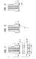
- Fig. 1 is an exploded sectional view of a vibration member of a rod-like vibration wave driven motor (to be simply referred to as a vibration wave driven motor hereinafter).
- a clamping surface 1e of an upper vibration member 1 for a piezo-electric element disk 3 is formed to be a tapered surface (angle ⁇ ) having a concave surface
- a clamping surface 2b of a lower vibration member 2 for a piezo-electric element disk 4 is also formed to be a tapered surface (angle ⁇ A) having a concave surface.
- the piezo-electric element disks 3 and 4 consisting of e.g., PZTs are clamped and fixed between the upper and lower vibration members 1 and 2 by a bolt 6 (not shown) like in the prior art
- the piezo-electric element disks 3 and 4 begin to gradually contact with the members 1 and 2 from the outer peripheral portions of the clamping surfaces 1e and 2b.
- the bolt 6 as a fastening member is fastened up to a predetermined value, the clamping surface 1e near a threaded hole 1d of the upper vibration member 1, and the clamping surface 2b near a bolt hole 2a of the lower vibration member 2 suffer from an increased strain.
- a pressure acting on the piezo-electric element disks 3 and 4 can be uniformed or almost uniformed with a compression force by other surface portions, or a compression force on the outer peripheral portions can be slightly increased by the portions with the increased strain.
- the entire surfaces of the piezo-electric element disks 3 and 4 can be compressed with an almost uniform pressure, or a pressure at the outer periphery side can be slightly larger than that at the inner periphery side. Therefore, the piezo-electric element disks 3 and 4 can be free from floating and excessive pressure portions in a driving state, thus improving vibration characteristics and efficiency.
- the clamping surfaces of the upper and lower vibration members 1 and 2 for the piezo-electric element disks are formed to be tapered surfaces having concave surfaces.
- the clamping surfaces may have a spherical shape, as shown in Fig. 2, or may have a curved surface shape for making a strain, i.e., a stress distribution of the piezo-electric element disks 3 and 4 constant, as shown in Fig. 3.
- the strain of the piezo-electric element disks can be more uniform, or a strain of their outer peripheral portions can be slightly larger than that at their inner peripheral portions.
- the concave surface of the clamping surface is formed by a curve f(r) which makes a strain of the piezo-electric element disks 3 and 4 constant, or a curve f(r) obtained to make a strain at an outer periphery side slightly larger than that at an inner periphery side. Both curves are obtained by theoretical calculations.
- the curve f(r) is constituted by a curve section having a large curvature at an outer periphery side, and a curve section having a small curvature at an inner periphery side.
- Fig. 7 shows a structure in which a lens barrel comprising a photographic lens is driven using the motor according to the present invention.
- a gear 12 is coaxially fitted on a moving member 8, and transmits a rotational output to a gear 13, thereby rotating a lens barrel 14 having a gear mated with the gear 13.
- an optical encoder slit disk 15 is arranged coaxially with the gear 13, and the position and speed are detected by a photocoupler 16.
- This mechanism also includes a spring post 9, a bearing 10, and a spring 11 for urging the vibration member against the moving member. Note that two piezo-electric element disks are stacked to increase a vibration amplitude.
- an axial strain, caused by clamping, of an electro-mechanical energy conversion element such as a piezo-electric element disk is substantially uniform at an outer periphery side, or an arbitrary strain distribution can be obtained. Therefore, the piezo-electric element disk does not easily crack upon clamping, and a motor with improved vibration characteristics and efficiency can be obtained.
- the contact surfaces of the vibration members 1 and 2, which are in contact with the piezo-electric element disks 3 and 4 are formed to be concave contact surfaces to change the rigidity of each vibration member, whereby a strain in the axial direction of the vibration member in the piezo-electric element disks 3 and 4 is consequently substantially uniform.
- a plastic spacer 20 may be inserted between the lower vibration member 2 and the piezo-electric element disk 4, or between the upper vibration member 1 and the piezo-electric element disk 3 as well as the former position, thus obtaining the same effect as in each of the above embodiments.
- the spacer 20 is a hollow spacer having the same diameter as those of the piezo-electric element disks 3 and 4, and the same inner diameters as those of the disks 3 and 4, and its outer peripheral portion is thicker than the inner peripheral portion.
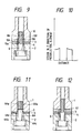
- Fig. 9 is a longitudinal sectional view of a vibration member of a vibration wave driven motor according to still another embodiment of the present invention.
- a recess portion 10b is formed in an inner portion of an end face 10a contacting a piezo-electric element disk 3.
- An inner threaded portion 10c which is threadably engaged with a threaded portion of a bolt 6 is formed in the vibration member 10 on the distal end side of the recess portion 10b.
- the end face of the vibration member 1 being contact with the piezo-electric element disk 3 coincides in the same plane with a screw end face 1d of the inner threaded portion of the vibration member 1, which portion is threadably engaged with the bolt 6.
- the end face of the inner threaded portion 10c is separated from the end face contacting the piezo-electric element disk 3 by a distance corresponding to the depth of the recess portion 10b, thereby forming a gap 10e, which is not threadably engaged with the bolt 6, between the inner wall surface of the recess portion 10b and the outer circumferential surface of the bolt 6.
- the piezo-electric element disks 3 and 4 are arranged between the end face of a lower vibration member 2 and the end face of the vibration member 10, and are clamped and fixed by the bolt 6 like in the prior art.
- a portion of the vibration member 10 where stress concentration most easily occurs by fastening the bolt 6 is a corner portion 10f of the bottom portion of the recess portion 10b.
- the corner portion 10f is separated from the end face 10a of the vibration member 10, which is in contact with the piezo-electric element disk 3, a clamping pressure applied to the piezo-electric element disks 3 and 4 can be almost uniformed.
- the contact end face of the piezo-electric element disk, and the end face of the inner threaded portion of the vibration member 10 for the bolt 6 are separated from each other in the axial direction by the gap 10e, thereby separating the portion 10f where stress concentration most easily occurs by the bolt 6 from the piezo-electric element disk, thereby averaging the clamping pressure applied to the piezo-electric element disks 3 and 4.
- the piezo-electric element disks 3 and 4 are clamped and fixed between the upper and lower vibration members 1 and 2 using a bolt 6A in place of the bolt 6 in the prior art shown in Fig. 4.
- the bolt 6A has a threaded portion 6Aa only on its distal end portion, thereby forming a gap around a shaft portion 6Ac between the threaded portion 6Aa and a head portion 6Ab.
- a ring-like distance plate 40 is interposed between the vibration member 1 and the piezo-electric element disk 3, thereby separating the end face of the vibration member 1 and the piezo-electric element disk 3 in the axial direction.
- a threaded portion 53 threadably engaged with a lower vibration member 52 is integrally formed on an upper vibration member 51, and a circumferential groove 54 is formed around the root portion of the threaded portion 53, thereby separating the end face of the vibration member 51, and the proximal end of the threaded portion 53 in the axial direction.
- a recess portion 56 is formed in the lower vibration member 52.
- a threaded portion 63 to be threadably engaged with an upper vibration member 61 is integrally formed on a lower vibration member 62 in contrast to the embodiment shown in Fig. 13.
- a circumferential groove 64 is formed like in the embodiment shown in Fig. 13.
- a recess portion 65 is formed in the upper vibration member 61, thereby separating, in the axial direction, the end face of the vibration member 61 and the end face of a threaded hole 66 to be threadably engaged with the threaded portion 63.
- a member 70 having low rigidity e.g., felt, rubber, resin, a flexible substrate, or the like is arranged in the gap 10e in the embodiment shown in Fig. 9.
- Fig. 16 shows a structure in which a lens barrel of an optical lens is driven using the motor according to the embodiment shown in Fig. 11.
- FIG. 17 shows another embodiment of a vibration wave driven motor according to the present invention.
- a metal vibration member B similar to a lower vibration member in a conventional motor has a threaded portion BB which is threadably engaged with a bolt E extending to a top portion ab of an upper vibration member a , and has a grooved portion d for increasing the diameter on the inner periphery side of the vibration member B.
- a bottom portion BA of the lower vibration member B is fixed to a portion of, e.g., a camera or a printer, and its top portion BC opposes a piezo-electric element C as an electro-mechanical energy conversion element, for example, a PZT.
- the piezo-electric element C is the same as a piezo-electric element of a known vibration wave driven motor, and is constituted by two piezo-electric elements C1 and C2.
- the vibration member a is the same as an upper vibration member of the conventional motor.
- the bolt E for clamping the piezo-electric element C by the upper and lower vibration members is substantially the same as a bolt of the conventional motor.
- a spring (not shown) which is the same as the spring 5 shown in Fig. 5 is attached to the bolt E, as shown in Fig. 5. With this spring, a rotor R (not shown; see Fig. 5) is urged against a portion of the vibration member a .
- Other constituting elements of the motor are the same as those in the prior art shown in Figs. 4 and 5, and a detailed description thereof will be omitted.
- Fig. 18 shows a radial distribution of a strain in a Z direction of the piezo-electric element when the piezo-electric element C is clamped by inserting the bolt E at the center of the vibration members a and B each having an outer diameter of 8 mm, and an inner diameter of 3 mm.
- a curve c represents characteristics when the diameter of the groove of the grooved portion d is 5.5 mm
- a curve b represents characteristics when the diameter of the groove is 6.0 mm.
- a change in strain of the piezo-electric element C is smallest when the diameter of the groove is 5.5 mm.
- the operation of the vibration wave driven motor shown in Fig. 17 is the same as that of the conventional motor, and a detailed description thereof will be omitted.
- Fig. 19 is a sectional view showing another embodiment of the present invention.
- a grooved portion d1 which is the same as the grooved portion d in Fig. 17 is also formed in an upper vibration member.
- the grooved portions d and d1 are formed in the upper and lower vibration members, the warp of the piezo-electric element can be eliminated, and an almost uniform deformation can be attained.
- a grooved portion similar to that in the above embodiment is constituted by a notched portion d2 and a washer K. With this method, a working process can also be facilitated.
- a portion of an upper vibration member A is extended to form a bolt E1 to be threadably engaged with the lower vibration member B.
- Other structures are substantially the same as the embodiment shown in Fig. 17.
- a portion of a lower vibration member B2 is extended to form a bolt E2 to be threadably engaged with the upper vibration member a contrary to the embodiment shown in Fig. 22.
- Other structures are substantially the same as the embodiment shown in Fig. 19, and a detailed description thereof will be omitted.
- silver electrode films 107 having a thickness of 2 to 3 ⁇ m are respectively formed on the two surfaces of a piezo-electric ceramic 106 having, e.g., an outer diameter of 15 mm, an inner diameter of 6.2 mm, and a thickness of 0.5 mm.
- the piezo-electric ceramic 106 comprises a three-component-based PZT prepared by adding the third component to a titanate zirconate, and has characteristics having a high mechanical quality coefficient suitable for a vibration wave driven vibration member.
- the piezo-electric ceramic 106 is a quite conventional, commercially available one prepared by molding and sintering a powder. The two surfaces of the ceramic 106 are subjected to a lapping treatment, and its inner and outer diameters are finished by a grinding process.
- Each electrode film 107 uses silver as a major component, and a commercially available paste consisting of frits and a solvent. These materials are screen-printed on the piezo-electric ceramic 106, and are baked at a temperature of about 800°C.
- the electrode film When an electrode film is formed by screen printing or deposition (to be described later), if the electrode film is formed on the entire surface of a piezo-electric element, the electrode film may extend to the end face of the piezo-electric element. In this case, when a voltage is applied to the piezo-electric element, it is short-circuited by the extended electrode film, and the piezo-electric element can no longer be used.
- a portion 108 having a width of 0.1 mm to 0.25 mm where no electrode film is formed is provided, thereby preventing short-circuiting.
- the portion where no electrode film is formed is formed on a peripheral portion, if the performance of a vibration member is impaired, and if any other problems are posed, a non - formation portion of the electrode film on the inner or outer peripheral portion can be removed by machining, thus solving the above problems.
- Fig. 30 is a sectional view showing an embodiment in which a vibration member 500 for a vibration wave driven motor is constituted by using a piezo-electric element 100 in the embodiment shown in Figs. 24A and 24B.
- Metal members 2-1 and 2-2 formed of brass have the same outer diameter, but have different inner diameters.
- a female screw portion is formed at the center of one metal member 2-1, while a hollow portion having a diameter (e.g., 6.2 mm) larger than that of the female screw portion is formed at the center of the other metal member 2-2.
- the total length of one metal member 2-1 is set to be 25 mm, and that of the other metal member 2-2 is set to be 15 mm.
- a spot facing portion for an M6 hexagon socket head cap bolt 6 is formed in the other metal member 2-1.
- Each electrode plate 300 formed of copper plates are interposed between the two piezo-electric elements 100 and the metal member 2-1, and are fastened by the M6 hexagon socket head cap bolt 6 via the metal members 2-1 and 2-2, thus forming the vibration member 500.
- Each electrode plate 300 is formed to have an outer diameter of 17.5 mm, an inner diameter of 6.2 mm, and a thickness of 0.2 mm in this embodiment.
- the non-electrode formation portion 108 where no electrode film is formed is present on and near the inner peripheral portion of the piezo-electric ceramic, and its radial length is equal to or larger than 1/2 the thickness of the piezo-electric ceramic.
- the length of this portion is preferably as small as possible.
- the portion where no electrode film 107 is formed does not directly contact the metal members 2-1 and 2-2 and the electrode plates 300, and does not receive a compression stress. As a result, the compression stress is applied to only the portion where the electrode film is formed.
- the minimum thickness of the electrode film 107 is limited to 2 to 3 ⁇ m even when contents of frits and a solvent in the paste are adjusted using various fine screens in conventional screen printing. If the thickness of the electrode film is increased, the metal members 2-1 and 2-2, and the piezo-electric ceramic 106 do not directly contact each other. Therefore, the same effect as described above can be obtained.
- a thinner film may be formed by metal deposition.
- the effect of this embodiment requires a thickness of 0.5 ⁇ m or more of the electrode film in practice.
- the above-described effect can be expected, if a difference between film thicknesses of the portion 107 where the electrode film is formed on the outer peripheral portion and the electrode film on the inner peripheral portion is 0.5 ⁇ m or more enough to disperse the compression stress to the outer peripheral portion.
- the material of the electrode film 107 is not limited to silver.
- platinum, silver-palladium, copper, nickel, and the like may be used.
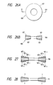
- the electrode films 107 are formed on the two surfaces of the piezo-electric ceramic 106 to have the non-electrode formation portions 108. As shown in Fig. 25, the electrode films 107 may be formed to have the non-electrode formation portion 108 on only one surface of the ceramic 106.
- Fig. 26B is a sectional view of a main part of a piezo-electric element according to another embodiment of the present invention.
- the thickness of each of electrode films 107 formed on two surfaces of a piezo-electric ceramic 106 is increased from the inner periphery side toward the outer periphery side.
- the electrode film 107 having a thickness of 2 to 3 ⁇ m on the inner peripheral portion, and a thickness of 6 to 9 ⁇ m on the outer peripheral portion is formed on each surface of the piezo-electric ceramic 106 having, e.g., an outer diameter of 15 mm, an inner diameter of 6.2 mm, and a thickness of 0.5 mm.
- the piezo-electric ceramic 106 comprises a three-component-based PZT prepared by adding the third component to a titanate zirconate, and has characteristics having a high mechanical quality coefficient suitable for a vibration wave driven vibration member.
- the piezo-electric ceramic 106 is a quite conventional, commercially available one prepared by molding and sintering a powder. The two surfaces of the ceramic 106 are subjected to a lapping treatment, and its inner and outer diameters are finished by a grinding process.
- Each electrode film 107 uses silver as a major component, and a commercially available paste consisting of frits and a solvent. These materials are screen-printed and stacked on the piezo-electric ceramic 106 several times.
- Fig. 27 shows a case wherein the electrode films are stacked in three formation processes.
- an electrode film 107-1 is formed by screen printing on the entire surface from the inner periphery toward the outer periphery.
- an electrode film 107-2 is formed by screen printing on the electrode film 107-1 from a position offset from the inner periphery to the outer periphery by 3 mm toward the outer peripheral edge.
- an electrode film 107-3 is formed by screen printing on the electrode film 107-2 from a position offset by 3 mm from the above-mentioned offset position to the outer peripheral edge.
- the formed films are baked at a temperature of about 800°C.
- the thickness of the electrode film is as described above.
- screen printing need only be performed several times. If the number of times of screen printing is increased, this requires troublesome operations, and corner portions of the electrode films formed by printing tend to be rounded upon baking. When printing was performed three times using three different screens, almost smooth changes in thickness could be obtained.
- the thickness of a resin film of a screen may be continuously changed to form the film in single screen printing.
- the present inventors examined various changes in thickness in addition to this embodiment.
- the thickness of the electrode film formed by screen printing is limited to a minimum of 2 to 3 ⁇ m, and in order to provide a smooth change in thickness from the inner peripheral portion toward the outer peripheral portion, screen printing must be performed about three times.
- the thickness of this embodiment is a minimum thickness of the electrode film 107 which can be formed by the screen printing method.
- a metal deposition method may be performed several times using masks having different sizes like in the screen printing method.
- the piezo-electric element 100 formed in this manner can be used in the vibration member shown in Fig. 30.
- an inclined electrode film may be formed on only one side, or as shown in Fig. 29B, the piezo-electric ceramic 106 may be tapered by a machining process, a grinding process, or a polishing process, and an electrode film having a uniform thickness may be formed, so that the thickness of the piezo-electric element itself can be apparently increased from the inner periphery side toward the outer periphery side.
- a compression stress acting on the piezo-electric element can be uniformed, and cracks which may be produced in the piezo-electric element can be prevented.
- the piezo-electric element can be fastened by a larger fastening force.
Landscapes
- General Electrical Machinery Utilizing Piezoelectricity, Electrostriction Or Magnetostriction (AREA)
Claims (15)
- Schwingungsmotor mit einem ersten Schwingungsbauteil (2, 20) mit einer Bohrung, die auf der Längsachse des Motors angeordnet ist, einem zweiten Schwingungsbauteil (1) mit einer Bohrung, die auf dieser Achse angeordnet ist, wenigstens einem elektro-mechanischen Energieumwandlungsbauteil (3, 4; 106) mit einer Bohrung, die auf der Achse angeordnet und zwischen dem ersten und dem zweiten Schwingungsbauteil vorgesehen ist, und einer Befestigungseinrichtung (6) zum Befestigen des Umwandlungsbauteils unter Kompressionsdruck zwischen dem ersten Schwingungsbauteil und dem zweiten Schwingungsbauteil; wobei das Umwandlungsbauteil zum Erzeugen einer Schwingungswelle im ersten und zweiten Schwingungsbauteil abhängig von einem dem Umwandlungsbauteil zugeführten elektrischen Signal dient,
dadurch gekennzeichnet, daß
wenigstens eine der Kontaktflächen zwischen dem ersten Schwingungsbauteil und dem Umwandlungsbauteil und zwischen dem Umwandlungsbauteil und dem zweiten Schwingungsbauteil als eine konkave Aussparung ausgebildet ist. - Schwingungsmotor nach Anspruch 1,
dadurch gekennzeichnet, daß
zwei Umwandlungselemente (3, 4) mit flachen Kontaktflächen zwischen dem ersten und dem zweiten Schwingungsbauteil vorgesehen sind, wobei jedes Schwingungsbauteil eine konkave Kontaktfläche hat. - Schwingungsmotor nach Anspruch 1,
dadurch gekennzeichnet, daß
das erste oder zweite Schwingungsbauteil zweigeteilt ausgebldet ist, von denen ein Teil deformierbar und mit der konkaven Aussparung versehen ist. - Schwingungsmotor nach Anspruch 1,
dadurch gekennzeichnet, daß
ein einziges Umwandlungselement vorgesehen ist, das eine scheibenförmige piezo-elektrische Keramikschicht hat, die auf jeder Kontaktfläche mit einem Elektrodenfilm (107) versehen ist, wobei jeder Film die konkave Aussparung definiert. - Schwingungsmotor nach Anspruch 4,
dadurch gekennzeichnet, daß
die konkave Aussparung kegelstumpfförmig (107), gestuft (107-1, 107-2, 107-3) ist, oder einen gewundenen Abschnitt (7) hat. - Schwingungsmotor nach Anspruch 1, 2 oder 3,
dadurch gekennzeichnet, daß
die Aussparung im ersten Schwingungsbauteil vorgesehen ist. - Schwingungsmotor nach Anspruch 1, 2 oder 3,
dadurch gekennzeichnet, daß
die Aussparung im zweiten Schwingungsbauteil vorgesehen ist. - Schwingungsmotor nach Anspruch 1, 2 oder 3,
dadurch gekennzeichnet, daß
die Aussparung im Umwandlungsbauteil vorgesehen ist. - Schwingungsmotor nach Anspruch 6, 7 oder 8,
dadurch gekennzeichnet, daß
die Aussparung eine Sphärenstumpfform hat. - Schwingungsmotor nach Anspruch 6, 7 oder 8,
dadurch gekennzeichnet, daß
die Aussparung eine gekrümmte Oberflächenform hat. - Schwingungsmotor nach einem der Ansprüche 1 bis 10,
dadurch gekennzeichnet, daß
die Befestigungseinrichtung zum Befestigen des ersten und zweiten Schwingungsbauteils und des wenigstens einen Umwandlungselements einen Schraubenbolzen (6) umfaßt, der sich durch eines der Schwingungsbauteile erstreckt und mit einem Gewinde in Eingriff ist, das in der Bohrung des anderen Schwingungselements vorgesehen ist. - Motor nach einem der Ansprüche 1 bis 11,
dadurch gekennzeichnet, daß
ein Schwingungsbauteil ein elastisches Bauteil ist. - Motor nach einem der Ansprüche 1 bis 12,
dadurch gekennzeichnet, daß
eines der Schwingungsbauteile (1) eine kegelstumpfförmige Fläche hat, die mit einer komplementären kegelstumpfförmigen Fläche eines Drehausgangsbauteils in Eingriff ist, wobei das Ausgangsbauteil durch die Wellenbewegung des einen Schwingungsbauteils antreibbar ist. - Objektivantriebssystem mit einem Motor nach einem der Ansprüche 1 bis 13, wobei ein Objektivtubus über Zahnräder mittels des Motors angetrieben wird.
- Fotoapparat mit einem Objektivantriebssystem nach Anspruch 14.
Applications Claiming Priority (8)
| Application Number | Priority Date | Filing Date | Title |
|---|---|---|---|
| JP02134317A JP3137194B2 (ja) | 1990-05-24 | 1990-05-24 | 振動波駆動装置 |
| JP2134316A JPH0429574A (ja) | 1990-05-24 | 1990-05-24 | 棒状超音波モータ |
| JP134317/90 | 1990-05-24 | ||
| JP134316/90 | 1990-05-24 | ||
| JP2206597A JPH0491680A (ja) | 1990-08-03 | 1990-08-03 | 超音波モータ |
| JP206597/90 | 1990-08-03 | ||
| JP2288135A JPH04162579A (ja) | 1990-10-25 | 1990-10-25 | 圧電素子 |
| JP288135/90 | 1990-10-25 |
Publications (2)
| Publication Number | Publication Date |
|---|---|
| EP0458638A1 EP0458638A1 (de) | 1991-11-27 |
| EP0458638B1 true EP0458638B1 (de) | 1997-04-09 |
Family
ID=27471819
Family Applications (1)
| Application Number | Title | Priority Date | Filing Date |
|---|---|---|---|
| EP91304684A Expired - Lifetime EP0458638B1 (de) | 1990-05-24 | 1991-05-23 | Schwingungswellenmotor |
Country Status (3)
| Country | Link |
|---|---|
| US (1) | US5508580A (de) |
| EP (1) | EP0458638B1 (de) |
| DE (1) | DE69125525T2 (de) |
Families Citing this family (13)
| Publication number | Priority date | Publication date | Assignee | Title |
|---|---|---|---|---|
| US6016821A (en) * | 1996-09-24 | 2000-01-25 | Puskas; William L. | Systems and methods for ultrasonically processing delicate parts |
| JP2925272B2 (ja) * | 1990-08-31 | 1999-07-28 | キヤノン株式会社 | 振動波モータ |
| DE69233721T2 (de) * | 1991-11-20 | 2009-01-08 | Canon K.K. | Vibrationsangetriebener Motor |
| DE4438876B4 (de) * | 1994-10-31 | 2004-04-01 | Pi Ceramic | Piezoelektrischer Motor |
| SE9502225L (sv) * | 1995-06-19 | 1996-09-16 | Tetra Laval Holdings & Finance | Anordning vid en drivenhet för en ultraljudsförseglingsenhet |
| AU723618B2 (en) * | 1996-06-21 | 2000-08-31 | Tetra Laval Holdings & Finance Sa | An arrangement in a drive unit for an ultrasound sealing unit |
| JPH1094274A (ja) * | 1996-09-11 | 1998-04-10 | Canon Inc | 振動型駆動装置およびこれを備えた装置 |
| JP3406165B2 (ja) * | 1996-12-09 | 2003-05-12 | 愛三工業株式会社 | 超音波振動子 |
| US6879988B2 (en) * | 2000-03-09 | 2005-04-12 | Pkware | System and method for manipulating and managing computer archive files |
| JP3566711B2 (ja) * | 2002-07-12 | 2004-09-15 | キヤノン株式会社 | 振動波駆動装置 |
| US7285895B2 (en) * | 2005-03-15 | 2007-10-23 | Crescendo Technologies, Llc | Ultrasonic medical device and method |
| US20060244340A1 (en) * | 2005-04-27 | 2006-11-02 | Marathe Kaustubh P | High power ultrasonic transducer |
| JP2014168736A (ja) * | 2013-03-01 | 2014-09-18 | Seidensha Electronics Co Ltd | ボルト締めランジュバン型振動子及びボルト締めランジュバン型振動子を用いた超音波溶着装置 |
Family Cites Families (19)
| Publication number | Priority date | Publication date | Assignee | Title |
|---|---|---|---|---|
| US3370186A (en) * | 1965-02-05 | 1968-02-20 | Blackstone Corp | Ultrasonic transducers |
| US3694675A (en) * | 1971-02-25 | 1972-09-26 | Eastman Kodak Co | Cooled ultrasonic transducer |
| SU907798A1 (ru) * | 1979-04-26 | 1982-02-23 | Специальное Проектно-Конструкторское И Технологическое Бюро Малых Электрических Машин Производственного Объединения "Эльфа" | Сенсорный переключатель |
| US4530138A (en) * | 1982-09-30 | 1985-07-23 | Westinghouse Electric Corp. | Method of making a transducer assembly |
| DE3330411A1 (de) * | 1983-08-23 | 1985-03-14 | Siemens AG, 1000 Berlin und 8000 München | Piezo-wandler |
| JPS60257777A (ja) * | 1984-06-04 | 1985-12-19 | Taga Denki Kk | ねじり振動装置 |
| US4633119A (en) * | 1984-07-02 | 1986-12-30 | Gould Inc. | Broadband multi-resonant longitudinal vibrator transducer |
| JPS61224881A (ja) * | 1985-03-29 | 1986-10-06 | Canon Inc | 振動波モ−タ |
| US4752711A (en) * | 1985-03-29 | 1988-06-21 | Canon Kabushiki Kaisha | Vibration wave motor |
| US4659014A (en) * | 1985-09-05 | 1987-04-21 | Delavan Corporation | Ultrasonic spray nozzle and method |
| US4728843A (en) * | 1985-11-11 | 1988-03-01 | Taga Electric Co., Ltd. | Ultrasonic vibrator and drive control method thereof |
| US4697117A (en) * | 1985-11-27 | 1987-09-29 | Taga Electric Co., Ltd. | Rotary ultrasonic motor |
| JPS62141980A (ja) * | 1985-12-16 | 1987-06-25 | Taga Denki Kk | 超音波振動子とその駆動制御方法 |
| US4757227A (en) * | 1986-03-24 | 1988-07-12 | Intersonics Incorporated | Transducer for producing sound of very high intensity |
| JP2524346B2 (ja) * | 1987-03-27 | 1996-08-14 | オリンパス光学工業株式会社 | 超音波モ−タ |
| DE3904070C2 (de) * | 1988-02-12 | 1997-02-20 | Ngk Spark Plug Co | Ultraschallmotor |
| JPH01234067A (ja) * | 1988-03-11 | 1989-09-19 | Nec Corp | 超音波モータ |
| US4965482A (en) * | 1988-06-17 | 1990-10-23 | Nec Corporation | Ultrasonic motor and method of adjusting the same |
| JP2935504B2 (ja) * | 1989-07-05 | 1999-08-16 | キヤノン株式会社 | モータ |
-
1991
- 1991-05-23 EP EP91304684A patent/EP0458638B1/de not_active Expired - Lifetime
- 1991-05-23 DE DE69125525T patent/DE69125525T2/de not_active Expired - Lifetime
-
1994
- 1994-08-26 US US08/296,976 patent/US5508580A/en not_active Expired - Lifetime
Also Published As
| Publication number | Publication date |
|---|---|
| DE69125525D1 (de) | 1997-05-15 |
| US5508580A (en) | 1996-04-16 |
| EP0458638A1 (de) | 1991-11-27 |
| DE69125525T2 (de) | 1997-09-04 |
Similar Documents
| Publication | Publication Date | Title |
|---|---|---|
| US5508580A (en) | Vibration wave driven motor | |
| JP3823340B2 (ja) | 振動モータ | |
| US4703214A (en) | Ultrasonic vibrator and its drive control method | |
| US6707232B2 (en) | Piezoelectric driving body, ultrasonic motor and electronic apparatus having an ultrasonic motor | |
| JPH10136665A (ja) | 圧電アクチュエータ | |
| US6201339B1 (en) | Piezoelectric actuator | |
| US5798598A (en) | Vibration driven device | |
| JPH04112686A (ja) | 振動波モータ | |
| US8675295B2 (en) | Piezoelectric actuator, lens barrel, and camera | |
| US7825566B2 (en) | Ultrasonic actuator and method for manufacturing piezoelectric deformation portion used in the same | |
| JPH0636673B2 (ja) | 駆動装置 | |
| JPH0740791B2 (ja) | 振動波モ−タ | |
| JP3016577B2 (ja) | 振動波装置 | |
| JPS62213585A (ja) | 振動波モ−タ | |
| GB2195821A (en) | Ultrasonic vibrator | |
| JPH09117168A (ja) | 超音波モータ | |
| JP2559729B2 (ja) | 振動発生器 | |
| CN119923792A (zh) | 振动式致动器和电子装置 | |
| US9300228B2 (en) | Vibratory drive apparatus using lubricant between elastic member and piezoelectric member | |
| JPH0491670A (ja) | 振動波駆動装置 | |
| JP2698412B2 (ja) | 振動波装置 | |
| JP2549310B2 (ja) | 超音波モータ | |
| JPH08163879A (ja) | 超音波振動子および超音波モータ | |
| JPS61295881A (ja) | 振動波モ−タ− | |
| JPS5893478A (ja) | 超音波モ−タ |
Legal Events
| Date | Code | Title | Description |
|---|---|---|---|
| PUAI | Public reference made under article 153(3) epc to a published international application that has entered the european phase |
Free format text: ORIGINAL CODE: 0009012 |
|
| AK | Designated contracting states |
Kind code of ref document: A1 Designated state(s): DE FR GB |
|
| 17P | Request for examination filed |
Effective date: 19920413 |
|
| 17Q | First examination report despatched |
Effective date: 19940912 |
|
| GRAG | Despatch of communication of intention to grant |
Free format text: ORIGINAL CODE: EPIDOS AGRA |
|
| GRAH | Despatch of communication of intention to grant a patent |
Free format text: ORIGINAL CODE: EPIDOS IGRA |
|
| GRAH | Despatch of communication of intention to grant a patent |
Free format text: ORIGINAL CODE: EPIDOS IGRA |
|
| GRAA | (expected) grant |
Free format text: ORIGINAL CODE: 0009210 |
|
| AK | Designated contracting states |
Kind code of ref document: B1 Designated state(s): DE FR GB |
|
| REF | Corresponds to: |
Ref document number: 69125525 Country of ref document: DE Date of ref document: 19970515 |
|
| ET | Fr: translation filed | ||
| PLBE | No opposition filed within time limit |
Free format text: ORIGINAL CODE: 0009261 |
|
| STAA | Information on the status of an ep patent application or granted ep patent |
Free format text: STATUS: NO OPPOSITION FILED WITHIN TIME LIMIT |
|
| 26N | No opposition filed | ||
| REG | Reference to a national code |
Ref country code: GB Ref legal event code: IF02 |
|
| PGFP | Annual fee paid to national office [announced via postgrant information from national office to epo] |
Ref country code: FR Payment date: 20090520 Year of fee payment: 19 |
|
| PGFP | Annual fee paid to national office [announced via postgrant information from national office to epo] |
Ref country code: GB Payment date: 20090527 Year of fee payment: 19 |
|
| PGFP | Annual fee paid to national office [announced via postgrant information from national office to epo] |
Ref country code: DE Payment date: 20100531 Year of fee payment: 20 |
|
| GBPC | Gb: european patent ceased through non-payment of renewal fee |
Effective date: 20100523 |
|
| REG | Reference to a national code |
Ref country code: FR Ref legal event code: ST Effective date: 20110131 |
|
| REG | Reference to a national code |
Ref country code: DE Ref legal event code: R071 Ref document number: 69125525 Country of ref document: DE |
|
| PG25 | Lapsed in a contracting state [announced via postgrant information from national office to epo] |
Ref country code: FR Free format text: LAPSE BECAUSE OF NON-PAYMENT OF DUE FEES Effective date: 20100531 |
|
| PG25 | Lapsed in a contracting state [announced via postgrant information from national office to epo] |
Ref country code: GB Free format text: LAPSE BECAUSE OF NON-PAYMENT OF DUE FEES Effective date: 20100523 |
|
| PG25 | Lapsed in a contracting state [announced via postgrant information from national office to epo] |
Ref country code: DE Free format text: LAPSE BECAUSE OF EXPIRATION OF PROTECTION Effective date: 20110524 |