EP0458663A1 - Automatische Maschine zum Montieren von Schliessblechen an Fenster- oder Türrahmen - Google Patents
Automatische Maschine zum Montieren von Schliessblechen an Fenster- oder Türrahmen Download PDFInfo
- Publication number
- EP0458663A1 EP0458663A1 EP91400972A EP91400972A EP0458663A1 EP 0458663 A1 EP0458663 A1 EP 0458663A1 EP 91400972 A EP91400972 A EP 91400972A EP 91400972 A EP91400972 A EP 91400972A EP 0458663 A1 EP0458663 A1 EP 0458663A1
- Authority
- EP
- European Patent Office
- Prior art keywords
- frame
- strikes
- machine according
- laying
- carriage
- Prior art date
- Legal status (The legal status is an assumption and is not a legal conclusion. Google has not performed a legal analysis and makes no representation as to the accuracy of the status listed.)
- Withdrawn
Links
- 238000009434 installation Methods 0.000 claims abstract description 19
- 238000004519 manufacturing process Methods 0.000 abstract description 2
- 238000006073 displacement reaction Methods 0.000 description 2
- 230000006978 adaptation Effects 0.000 description 1
- 238000010276 construction Methods 0.000 description 1
- 238000005553 drilling Methods 0.000 description 1
- 230000003100 immobilizing effect Effects 0.000 description 1
- 238000003801 milling Methods 0.000 description 1
Images

Classifications
-
- E—FIXED CONSTRUCTIONS
- E05—LOCKS; KEYS; WINDOW OR DOOR FITTINGS; SAFES
- E05B—LOCKS; ACCESSORIES THEREFOR; HANDCUFFS
- E05B17/00—Accessories in connection with locks
- E05B17/06—Templates for marking the position of apertures in fittings of wings or frames; Apparatus for installation of a lockset
-
- B—PERFORMING OPERATIONS; TRANSPORTING
- B23—MACHINE TOOLS; METAL-WORKING NOT OTHERWISE PROVIDED FOR
- B23P—METAL-WORKING NOT OTHERWISE PROVIDED FOR; COMBINED OPERATIONS; UNIVERSAL MACHINE TOOLS
- B23P19/00—Machines for simply fitting together or separating metal parts or objects, or metal and non-metal parts, whether or not involving some deformation; Tools or devices therefor so far as not provided for in other classes
- B23P19/04—Machines for simply fitting together or separating metal parts or objects, or metal and non-metal parts, whether or not involving some deformation; Tools or devices therefor so far as not provided for in other classes for assembling or disassembling parts
-
- B—PERFORMING OPERATIONS; TRANSPORTING
- B23—MACHINE TOOLS; METAL-WORKING NOT OTHERWISE PROVIDED FOR
- B23P—METAL-WORKING NOT OTHERWISE PROVIDED FOR; COMBINED OPERATIONS; UNIVERSAL MACHINE TOOLS
- B23P2700/00—Indexing scheme relating to the articles being treated, e.g. manufactured, repaired, assembled, connected or other operations covered in the subgroups
- B23P2700/08—Fittings for doors and windows of buildings
-
- Y—GENERAL TAGGING OF NEW TECHNOLOGICAL DEVELOPMENTS; GENERAL TAGGING OF CROSS-SECTIONAL TECHNOLOGIES SPANNING OVER SEVERAL SECTIONS OF THE IPC; TECHNICAL SUBJECTS COVERED BY FORMER USPC CROSS-REFERENCE ART COLLECTIONS [XRACs] AND DIGESTS
- Y10—TECHNICAL SUBJECTS COVERED BY FORMER USPC
- Y10T—TECHNICAL SUBJECTS COVERED BY FORMER US CLASSIFICATION
- Y10T29/00—Metal working
- Y10T29/53—Means to assemble or disassemble
- Y10T29/53004—Means to assemble or disassemble with means to regulate operation by use of templet, tape, card or other replaceable information supply
-
- Y—GENERAL TAGGING OF NEW TECHNOLOGICAL DEVELOPMENTS; GENERAL TAGGING OF CROSS-SECTIONAL TECHNOLOGIES SPANNING OVER SEVERAL SECTIONS OF THE IPC; TECHNICAL SUBJECTS COVERED BY FORMER USPC CROSS-REFERENCE ART COLLECTIONS [XRACs] AND DIGESTS
- Y10—TECHNICAL SUBJECTS COVERED BY FORMER USPC
- Y10T—TECHNICAL SUBJECTS COVERED BY FORMER US CLASSIFICATION
- Y10T29/00—Metal working
- Y10T29/53—Means to assemble or disassemble
- Y10T29/53313—Means to interrelatedly feed plural work parts from plural sources without manual intervention
- Y10T29/53378—Means to interrelatedly feed plural work parts from plural sources without manual intervention including converging conveyors
-
- Y—GENERAL TAGGING OF NEW TECHNOLOGICAL DEVELOPMENTS; GENERAL TAGGING OF CROSS-SECTIONAL TECHNOLOGIES SPANNING OVER SEVERAL SECTIONS OF THE IPC; TECHNICAL SUBJECTS COVERED BY FORMER USPC CROSS-REFERENCE ART COLLECTIONS [XRACs] AND DIGESTS
- Y10—TECHNICAL SUBJECTS COVERED BY FORMER USPC
- Y10T—TECHNICAL SUBJECTS COVERED BY FORMER US CLASSIFICATION
- Y10T29/00—Metal working
- Y10T29/53—Means to assemble or disassemble
- Y10T29/53313—Means to interrelatedly feed plural work parts from plural sources without manual intervention
- Y10T29/53383—Means to interrelatedly feed plural work parts from plural sources without manual intervention and means to fasten work parts together
Definitions
- the present invention relates to an automatic striker fitting machine.
- this machine is intended to equip window frames or French windows.
- the frame is intended to receive one or more openings.
- the frame comprises in addition to a conventional frame one or more crosspieces or one or more uprights and the frame is then made up of several sub-frames.
- the machine according to the invention allows the installation of strikes whatever the constitution of the frame to be fitted.
- the frame In order to allow the mounting of the opening (s), the frame must be fitted with various fittings and in particular with appropriate strikes.
- strikes are fitted to the entire periphery of the frame and it is customary to speak of perimeter fitting or perimeter closure.
- the material constituting the frame is treated or milled to receive the installation components which are as for them fixed manually.
- semi-automatic machines which are made up of individual machines erected in line and in front of which we pass either an upright or a crosspiece.
- current machines still require the presence of operators for certain manipulations of the frame or frame or the tool.
- current semi-automatic lines require various tools or automata and in the end very often the manual station is kept because it is more profitable than a machine that automates work only for a specific application.
- the object of the invention is to produce a fully automatic machine operating whatever the type of strike or the type of frame, any manual intervention being eliminated, and the bare frame being brought automatically to the machine.
- the present machine allows the installation of both conventional upper strikes as well as lower strikes, the latter being used in particular for tilt and turn equipment.
- the automatic strike laying machine on window or French window frames intended for equipping prefabricated frame frames and associated with a frame feeding device according to the invention comprises at least one unit. laying of automatic relative displacement relative to the frame of the frame.
- this installation unit is equipped with installation tools and mainly with at least one screwing station and a strike positioning drawer.
- the laying unit is mounted on a carriage which can be moved longitudinally on a beam which is itself translatable in the direction perpendicular to the direction of movement of the carriage on a portal frame.
- This embodiment is preferred, but the same result can be obtained by producing a fixed laying unit and by slaving the table on the transfer band supporting the frame.
- the machine comprises at least a second striker laying unit of identical construction and mounting to the first unit.
- This second unit is preferably connected to a jack, the body of which is fixed to the gantry frame so that it can be retracted or, on the contrary, brought into the working position depending on the type of frame to be fitted.
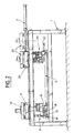
- Figures 1 and 2 show only the automatic striker installation machine per se. On the frame equipment line, it is associated with means for fitting the frame, the latter being disposed on the outside face on the belt and the upper cross member downstream in the direction of movement.
- the machine comprises, as a support, a chassis or gantry 1 equipped with means for moving the frame, preferably with a transfer band as well as means for immobilizing the frame, a once it arrived in equipment positioning.
- the chassis 1 is provided with two rails 4 and 5 on which two beams 10 and 20 are arranged.
- Each of these beams has longitudinal rails 11 and 12, 21 and 22 on which a strike-laying module P1, P2 moves longitudinally at each beam.
- Figure 1 shows the machine when the frame D is positioned and locked in the equipment position, and the installation modules P1 and P2 ready for mounting the strikes.
- One of the beams 20 is connected to a pneumatic cylinder or equivalent 2, this cylinder 2 acting to retract the beam 20 or, on the contrary, allow it to operate in the case of equipment of the lower cross member of the frame by lower strikes.
- the other beam 10 has a controlled stroke to come to equip the upper cross member as well as possibly the uprights of the frame D.
- the laying module P2 is therefore moved on the rails 21, 22 of the beam 20 by simple translation and rotation without the need for intermediate positioning from 0 ° to 180 ° to place the strikes at the lower corners of the dormant.
- the upper strike module P1 is equipped with a 180 ° rotation device in order to equip on the one hand the upper cross member and on the other hand possibly the uprights of the frame D.
- Each installation module is therefore mainly equipped with a rotating was relative to the carriage 10, 20 in order to allow the installation tools to rotate.
- These installation tools are in particular visible in FIG. 2, they include a strike supply hose 17, 27, a screwing station 14 with which screw supply hoses are associated 18, a holding device 15 and a striker positioning drawer 16.
- the installation tools to allow adaptation to any type of frame are also vertically movable.
- the parts which must be supplied with the laying tools are stored and supplied by vibrating bowl systems associated with a flexible hose so that the parts storage means does not have to follow the movement of the laying tools.
- the installation tools are placed at the installation location, the installation and fixing of the type of strike being also selected by program.
- the positioning drawer 16 is lowered by jack to the working location of the corresponding frame D and the keeper is released from the drawer 16 and held by a holding device 15 which possibly can also be used of template. Then it is the screwing device 14 which is maneuvered to ensure the screwing and to do so it has two heads supplied by a screw supply hose 18. These two screwing heads can be fixed one with respect to the 'other when the fixing dimensions are standard or their distances can be adjustable according to the drawer 16 then serving as a template for positioning and screwing at the locations of the striker orifices.
- the devices described above equip the laying unit P1 and also the laying unit P2.
- the latter can also receive other frame finishing tools such as milling, drilling, etc. as required.
- the installation unit includes the tooling devices described above, only the relative positioning between the installation unit and the frame being reversed.
Landscapes
- Engineering & Computer Science (AREA)
- Mechanical Engineering (AREA)
- Automatic Assembly (AREA)
Applications Claiming Priority (2)
| Application Number | Priority Date | Filing Date | Title |
|---|---|---|---|
| FR9006303 | 1990-05-21 | ||
| FR9006303A FR2662107B1 (fr) | 1990-05-21 | 1990-05-21 | Machine automatique de pose de gaches sur des dormants de fenetres ou de porte-fenetres. |
Publications (1)
| Publication Number | Publication Date |
|---|---|
| EP0458663A1 true EP0458663A1 (de) | 1991-11-27 |
Family
ID=9396792
Family Applications (1)
| Application Number | Title | Priority Date | Filing Date |
|---|---|---|---|
| EP91400972A Withdrawn EP0458663A1 (de) | 1990-05-21 | 1991-04-11 | Automatische Maschine zum Montieren von Schliessblechen an Fenster- oder Türrahmen |
Country Status (7)
| Country | Link |
|---|---|
| US (1) | US5140743A (de) |
| EP (1) | EP0458663A1 (de) |
| JP (1) | JPH0557543A (de) |
| CA (1) | CA2040359A1 (de) |
| FI (1) | FI911759A7 (de) |
| FR (1) | FR2662107B1 (de) |
| NO (1) | NO911932L (de) |
Cited By (2)
| Publication number | Priority date | Publication date | Assignee | Title |
|---|---|---|---|---|
| EP0683297A1 (de) * | 1994-05-20 | 1995-11-22 | August Winkhaus GmbH & Co KG | Verfahren zur montageautomaten-unterstützten Montage von Beschlagsteilen an den Flügel eines Fensters, einer Tür oder dergleichen |
| EP0884131A3 (de) * | 1997-06-12 | 1999-04-21 | Wegoma GmbH Maschinenfabrik in Konkurs | Vorrichtung zur Verschraubung von einem Beschlagteil mit einem Flügelrahmen |
Families Citing this family (9)
| Publication number | Priority date | Publication date | Assignee | Title |
|---|---|---|---|---|
| DE4444178C5 (de) * | 1994-12-12 | 2013-02-07 | Afs Federhenn Maschinen Gmbh | Verfahren zum Verkoppeln eines ersten Beschlags mit einem zweiten Beschlag und Vorrichtung für die automatische Montage von Beschlägen an Fenstern und dergleichen |
| DE4445888B4 (de) * | 1994-12-22 | 2004-10-21 | Afs Federhenn Maschinen Gmbh | Vorrichtung zum Anbringen von Beschlägen oder dergleichen an einem Fensterflügel und dergleichen |
| DE19712082C2 (de) * | 1997-03-22 | 2001-08-23 | Lemuth Praez Steile Gmbh | Vorrichtung zur automatischen Montage von Beschlagteilen an den Flügeln eines Fensters oder dergleichen |
| DE19812411A1 (de) * | 1998-03-20 | 1999-09-23 | Federhenn Maschinen Gmbh | Vorrichtung für die Montage von Fensterflügeln und dergleichen |
| DE19817610B4 (de) * | 1998-04-21 | 2010-02-18 | Afs Federhenn Maschinen Gmbh | Montagetisch |
| DE19843269A1 (de) * | 1998-09-21 | 2000-03-30 | Roto Frank Ag | Verfahren zur maschinellen Montage von Beschlagteilen an Flügel- und/oder Blendrahmen von Fenstern, Türen oder dergleichen und Vorrichtung zur maschinellen Montage von Beschlagteilen an Flügel- und/oder Blendrahmen von Fenstern, Türen oder dergleichen |
| DE10052158A1 (de) * | 2000-10-20 | 2002-05-02 | R & R Sondermaschinen Gmbh | Verfahren und Vorrichtung zur Montage von Sprossen in einem Rahmen |
| JP5807750B2 (ja) * | 2012-01-05 | 2015-11-10 | トヨタ自動車株式会社 | 締付装置及び締付方法 |
| CN114310269B (zh) * | 2021-11-10 | 2024-03-22 | 浙江东建幕墙工程有限公司 | 一种门窗生产用加工装置 |
Citations (5)
| Publication number | Priority date | Publication date | Assignee | Title |
|---|---|---|---|---|
| DE2361926A1 (de) * | 1973-07-13 | 1975-01-30 | Elektroprojekt Anlagenbau Veb | Einrichtung zum elektronisch gesteuerten montieren und fuegen von bauteilen, insbesondere zur herstellung von rahmen |
| EP0240968A2 (de) * | 1986-04-04 | 1987-10-14 | Klaus Knaust | Vorrichtung zum maschinellen Eindrücken von Dichtungen |
| DE8908450U1 (de) * | 1989-07-11 | 1989-09-07 | Mayer & Co., Salzburg | Vorrichtung zur Montage von Beschlagteilen |
| EP0387124A1 (de) * | 1989-03-09 | 1990-09-12 | FERCO INTERNATIONAL Usine de Ferrures de BÀ¢timent Société à responsabilité limitée | Vorrichtung zum automatischen Eindrücken von Dichtungen, insbesondere von einer Dichtung in einer Nut eines Fensters |
| EP0401094A1 (de) * | 1989-06-01 | 1990-12-05 | FERCO INTERNATIONAL Usine de Ferrures de BÀ¢timent Société à responsabilité limitée | Einrichtung zur Endbearbeitung von Fensterrahmen |
Family Cites Families (6)
| Publication number | Priority date | Publication date | Assignee | Title |
|---|---|---|---|---|
| US3979817A (en) * | 1974-11-04 | 1976-09-14 | Norfield Manufacturing Co. | Door hinge applying method |
| GB2022664A (en) * | 1977-12-17 | 1979-12-19 | Rivers Machinery Ltd | Improvements relating to apparatus for assembling windows |
| US4175313A (en) * | 1978-04-20 | 1979-11-27 | Neumann Paul G | Method and apparatus for manufacturing door frames |
| GB2047214B (en) * | 1979-01-16 | 1982-12-01 | Crompton Nettlefold Stenman | Hinge applying apparatus |
| US4819324A (en) * | 1986-09-30 | 1989-04-11 | The Boeing Company | Nutplate installation tool |
| FR2647150B1 (fr) * | 1989-05-17 | 1991-08-09 | Ferco Int Usine Ferrures | Machine de pose automatique de joint souple en particulier d'un joint de fond de vitrage ou d'un joint de parclose |
-
1990
- 1990-05-21 FR FR9006303A patent/FR2662107B1/fr not_active Expired - Fee Related
-
1991
- 1991-04-11 FI FI911759A patent/FI911759A7/fi unknown
- 1991-04-11 EP EP91400972A patent/EP0458663A1/de not_active Withdrawn
- 1991-04-12 CA CA002040359A patent/CA2040359A1/fr not_active Abandoned
- 1991-05-02 US US07/694,483 patent/US5140743A/en not_active Expired - Fee Related
- 1991-05-16 NO NO91911932A patent/NO911932L/no unknown
- 1991-05-17 JP JP3141473A patent/JPH0557543A/ja active Pending
Patent Citations (5)
| Publication number | Priority date | Publication date | Assignee | Title |
|---|---|---|---|---|
| DE2361926A1 (de) * | 1973-07-13 | 1975-01-30 | Elektroprojekt Anlagenbau Veb | Einrichtung zum elektronisch gesteuerten montieren und fuegen von bauteilen, insbesondere zur herstellung von rahmen |
| EP0240968A2 (de) * | 1986-04-04 | 1987-10-14 | Klaus Knaust | Vorrichtung zum maschinellen Eindrücken von Dichtungen |
| EP0387124A1 (de) * | 1989-03-09 | 1990-09-12 | FERCO INTERNATIONAL Usine de Ferrures de BÀ¢timent Société à responsabilité limitée | Vorrichtung zum automatischen Eindrücken von Dichtungen, insbesondere von einer Dichtung in einer Nut eines Fensters |
| EP0401094A1 (de) * | 1989-06-01 | 1990-12-05 | FERCO INTERNATIONAL Usine de Ferrures de BÀ¢timent Société à responsabilité limitée | Einrichtung zur Endbearbeitung von Fensterrahmen |
| DE8908450U1 (de) * | 1989-07-11 | 1989-09-07 | Mayer & Co., Salzburg | Vorrichtung zur Montage von Beschlagteilen |
Cited By (2)
| Publication number | Priority date | Publication date | Assignee | Title |
|---|---|---|---|---|
| EP0683297A1 (de) * | 1994-05-20 | 1995-11-22 | August Winkhaus GmbH & Co KG | Verfahren zur montageautomaten-unterstützten Montage von Beschlagsteilen an den Flügel eines Fensters, einer Tür oder dergleichen |
| EP0884131A3 (de) * | 1997-06-12 | 1999-04-21 | Wegoma GmbH Maschinenfabrik in Konkurs | Vorrichtung zur Verschraubung von einem Beschlagteil mit einem Flügelrahmen |
Also Published As
| Publication number | Publication date |
|---|---|
| JPH0557543A (ja) | 1993-03-09 |
| US5140743A (en) | 1992-08-25 |
| FR2662107B1 (fr) | 1993-06-25 |
| CA2040359A1 (fr) | 1991-11-22 |
| FI911759A7 (fi) | 1991-11-22 |
| FI911759A0 (fi) | 1991-04-11 |
| NO911932L (no) | 1991-11-22 |
| FR2662107A1 (fr) | 1991-11-22 |
| NO911932D0 (no) | 1991-05-16 |
Similar Documents
| Publication | Publication Date | Title |
|---|---|---|
| FR2662107A1 (fr) | Machine automatique de pose de gaches sur des dormants de fenetres ou de porte-fenetres. | |
| CZ291102B6 (cs) | Způsob montáľe částí kování za podpory montáľních automatů | |
| US3748965A (en) | Angularly adjustable attachment for a machine tool headstock | |
| EP0388296B1 (de) | Interventionsvorrichtung, insbesondere zur Prüfung, Inspektion und Wartung von Wärmeaustauschern | |
| US5458381A (en) | Door with a latch and/or bolt lock and handle mounting for same | |
| CA2017494A1 (fr) | Installation pour la finition de chassis de fenetres | |
| FR2645576A1 (fr) | Systeme formant support d'au moins un gabarit de percage, notamment utilise pour le montage d'une serrure a encastrer dans une porte | |
| CN118809322A (zh) | 磨床及其控制方法、介质、计算机设备 | |
| EP0094883B1 (de) | Schervorrichtung für bestrahlte Brennstoffbündel | |
| FR2627117A1 (fr) | Dispositif d'assemblage des pieces d'un renvoi d'angle | |
| DE3247202C1 (de) | Bohrgerät | |
| CA2064663A1 (fr) | Machine de pose de ferrures sur des profiles, notamment de pose de gaches sur des profiles destines, apres assemblage ulterieur, a constituer des dormants de porte ou fenetre | |
| EP0444988A1 (de) | Automatische Maschine zum Befestigen von Teilen auf Tür- oder Fensterpfosten | |
| EP0494572A1 (de) | Vorrichtung zum Zusammenbauen von Teilen auf einer Stulpschiene eines Treibstangenverschlusses für einen Drehkippflügel eines Fensters | |
| CA2245081A1 (en) | Machine for the production of metal sheet panels with bent edges | |
| CN109500973A (zh) | 一种锁具木门安装打孔装置 | |
| CA2020491A1 (fr) | Installation pour l'assemblage automatique d'un dispositif de ferrure en particulier d'un verrouillage lateral destine a etre monte sur les ouvrants, notamment de fenetres oscillo-battantes | |
| FR2970020A1 (fr) | Dispositif pour l'installation d'un ouvrant dans un dormant | |
| JPH04226843A (ja) | 開放窓又はドアのフレームの直立部材又はクロスメンバに取付け金具又は周辺取付け金具部品を取付けるための自動機械 | |
| CZ66594A3 (en) | Device for liquidating old glazed windows | |
| KR102813809B1 (ko) | 분골 수거 장치 | |
| EP1013985A2 (de) | Sicherheitsvorrichtung für einen Industrieraum, Tür mit einer solchen Vorrichtung und Raum mit einer solchen Tür | |
| JPH0691396A (ja) | ワーク反転装置における回転体開閉部のロック装置 | |
| CA2107614A1 (fr) | Compas-charniere pour fenetre a l'italienne | |
| CN221068605U (zh) | 一种辅助进料装置及封边机 |
Legal Events
| Date | Code | Title | Description |
|---|---|---|---|
| PUAI | Public reference made under article 153(3) epc to a published international application that has entered the european phase |
Free format text: ORIGINAL CODE: 0009012 |
|
| AK | Designated contracting states |
Kind code of ref document: A1 Designated state(s): AT BE CH DE DK ES GB GR IT LI LU NL SE |
|
| 17P | Request for examination filed |
Effective date: 19920331 |
|
| 17Q | First examination report despatched |
Effective date: 19930304 |
|
| STAA | Information on the status of an ep patent application or granted ep patent |
Free format text: STATUS: THE APPLICATION IS DEEMED TO BE WITHDRAWN |
|
| 18D | Application deemed to be withdrawn |
Effective date: 19930720 |