EP0458680A1 - Vorrichtung zum gleichzeitigen Positionieren von mehreren Schraubverbindungselementen - Google Patents
Vorrichtung zum gleichzeitigen Positionieren von mehreren Schraubverbindungselementen Download PDFInfo
- Publication number
- EP0458680A1 EP0458680A1 EP91401261A EP91401261A EP0458680A1 EP 0458680 A1 EP0458680 A1 EP 0458680A1 EP 91401261 A EP91401261 A EP 91401261A EP 91401261 A EP91401261 A EP 91401261A EP 0458680 A1 EP0458680 A1 EP 0458680A1
- Authority
- EP
- European Patent Office
- Prior art keywords
- support member
- connecting elements
- axes
- threaded connecting
- threads
- Prior art date
- Legal status (The legal status is an assumption and is not a legal conclusion. Google has not performed a legal analysis and makes no representation as to the accuracy of the status listed.)
- Granted
Links
Images


Classifications
-
- B—PERFORMING OPERATIONS; TRANSPORTING
- B23—MACHINE TOOLS; METAL-WORKING NOT OTHERWISE PROVIDED FOR
- B23Q—DETAILS, COMPONENTS, OR ACCESSORIES FOR MACHINE TOOLS, e.g. ARRANGEMENTS FOR COPYING OR CONTROLLING; MACHINE TOOLS IN GENERAL CHARACTERISED BY THE CONSTRUCTION OF PARTICULAR DETAILS OR COMPONENTS; COMBINATIONS OR ASSOCIATIONS OF METAL-WORKING MACHINES, NOT DIRECTED TO A PARTICULAR RESULT
- B23Q3/00—Devices holding, supporting, or positioning work or tools, of a kind normally removable from the machine
- B23Q3/18—Devices holding, supporting, or positioning work or tools, of a kind normally removable from the machine for positioning only
-
- B—PERFORMING OPERATIONS; TRANSPORTING
- B23—MACHINE TOOLS; METAL-WORKING NOT OTHERWISE PROVIDED FOR
- B23P—METAL-WORKING NOT OTHERWISE PROVIDED FOR; COMBINED OPERATIONS; UNIVERSAL MACHINE TOOLS
- B23P19/00—Machines for simply fitting together or separating metal parts or objects, or metal and non-metal parts, whether or not involving some deformation; Tools or devices therefor so far as not provided for in other classes
- B23P19/10—Aligning parts to be fitted together
-
- B—PERFORMING OPERATIONS; TRANSPORTING
- B23—MACHINE TOOLS; METAL-WORKING NOT OTHERWISE PROVIDED FOR
- B23P—METAL-WORKING NOT OTHERWISE PROVIDED FOR; COMBINED OPERATIONS; UNIVERSAL MACHINE TOOLS
- B23P19/00—Machines for simply fitting together or separating metal parts or objects, or metal and non-metal parts, whether or not involving some deformation; Tools or devices therefor so far as not provided for in other classes
- B23P19/10—Aligning parts to be fitted together
- B23P19/12—Alignment of parts for insertion into bores
-
- Y—GENERAL TAGGING OF NEW TECHNOLOGICAL DEVELOPMENTS; GENERAL TAGGING OF CROSS-SECTIONAL TECHNOLOGIES SPANNING OVER SEVERAL SECTIONS OF THE IPC; TECHNICAL SUBJECTS COVERED BY FORMER USPC CROSS-REFERENCE ART COLLECTIONS [XRACs] AND DIGESTS
- Y10—TECHNICAL SUBJECTS COVERED BY FORMER USPC
- Y10T—TECHNICAL SUBJECTS COVERED BY FORMER US CLASSIFICATION
- Y10T29/00—Metal working
- Y10T29/53—Means to assemble or disassemble
- Y10T29/53022—Means to assemble or disassemble with means to test work or product
-
- Y—GENERAL TAGGING OF NEW TECHNOLOGICAL DEVELOPMENTS; GENERAL TAGGING OF CROSS-SECTIONAL TECHNOLOGIES SPANNING OVER SEVERAL SECTIONS OF THE IPC; TECHNICAL SUBJECTS COVERED BY FORMER USPC CROSS-REFERENCE ART COLLECTIONS [XRACs] AND DIGESTS
- Y10—TECHNICAL SUBJECTS COVERED BY FORMER USPC
- Y10T—TECHNICAL SUBJECTS COVERED BY FORMER US CLASSIFICATION
- Y10T29/00—Metal working
- Y10T29/53—Means to assemble or disassemble
- Y10T29/53039—Means to assemble or disassemble with control means energized in response to activator stimulated by condition sensor
- Y10T29/53061—Responsive to work or work-related machine element
-
- Y—GENERAL TAGGING OF NEW TECHNOLOGICAL DEVELOPMENTS; GENERAL TAGGING OF CROSS-SECTIONAL TECHNOLOGIES SPANNING OVER SEVERAL SECTIONS OF THE IPC; TECHNICAL SUBJECTS COVERED BY FORMER USPC CROSS-REFERENCE ART COLLECTIONS [XRACs] AND DIGESTS
- Y10—TECHNICAL SUBJECTS COVERED BY FORMER USPC
- Y10T—TECHNICAL SUBJECTS COVERED BY FORMER US CLASSIFICATION
- Y10T29/00—Metal working
- Y10T29/53—Means to assemble or disassemble
- Y10T29/531—Nuclear device
-
- Y—GENERAL TAGGING OF NEW TECHNOLOGICAL DEVELOPMENTS; GENERAL TAGGING OF CROSS-SECTIONAL TECHNOLOGIES SPANNING OVER SEVERAL SECTIONS OF THE IPC; TECHNICAL SUBJECTS COVERED BY FORMER USPC CROSS-REFERENCE ART COLLECTIONS [XRACs] AND DIGESTS
- Y10—TECHNICAL SUBJECTS COVERED BY FORMER USPC
- Y10T—TECHNICAL SUBJECTS COVERED BY FORMER US CLASSIFICATION
- Y10T29/00—Metal working
- Y10T29/53—Means to assemble or disassemble
- Y10T29/53961—Means to assemble or disassemble with work-holder for assembly
-
- Y—GENERAL TAGGING OF NEW TECHNOLOGICAL DEVELOPMENTS; GENERAL TAGGING OF CROSS-SECTIONAL TECHNOLOGIES SPANNING OVER SEVERAL SECTIONS OF THE IPC; TECHNICAL SUBJECTS COVERED BY FORMER USPC CROSS-REFERENCE ART COLLECTIONS [XRACs] AND DIGESTS
- Y10—TECHNICAL SUBJECTS COVERED BY FORMER USPC
- Y10T—TECHNICAL SUBJECTS COVERED BY FORMER US CLASSIFICATION
- Y10T29/00—Metal working
- Y10T29/53—Means to assemble or disassemble
- Y10T29/53978—Means to assemble or disassemble including means to relatively position plural work parts
Definitions
- the present invention relates to a device for simultaneously positioning several threaded connecting elements for fixing a part to an appliance.
- a threaded connection element consisting for example of studs is used to removably fix a part on an appliance.
- the cover is fixed to the tank by studs which are screwed into threads provided in the upper part of said tank and which penetrate into through bores provided in the flange of the cover and corresponding to said threads.
- said studs are arranged on a support member which, in the case of a nuclear reactor tank, consists for example of a ring rigid on which said studs are uniformly distributed in polar symmetry.
- centering the studs by relative to the through holes of the cover and relative to the threads of the tank is produced by vertically moving the support member which is positioned axially with respect to the axis of the cover and which is guided by a set of rails arranged externally on the upper part said cover, itself being mounted on the tank.
- the threads located on the tank have a diametrical position relative to the main axis of said tank.
- the ideal positioning that is to say a perfect superposition of the axis of a stud with the axis of a corresponding tapping can only be obtained by coincidence, which is far from being a satisfactory situation, and which is unacceptable for repetitive operations, carried out for example in a confined environment.
- the object of the present invention is therefore to propose a device which makes it possible to align and position the threaded connecting elements in the extension of the corresponding threads, the axes of said threads being retained as the reference axis.
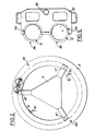
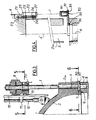
- the device according to the invention as shown in Figs 1 and 2 is used for the simultaneous positioning of several threaded connecting elements 1, constituted for example by studs and intended for fixing a cover 2 on a tank 3 for example of a nuclear reactor.
- the tank 3 comprises, in the upper part, a set of threads 4 distributed symmetrically on a circumference concentric with the main axis of said tank and intended to each receive the threaded end of a connecting element 1 .
- the cover 2 is provided with a peripheral flange 2a pierced with through bores 5 corresponding to the threads 4 of the tank 3 and distributed symmetrically on a circumference concentric with respect to the main axis of said cover.
- Each through bore 5 is intended for the passage of a threaded connecting element 1.
- the inner periphery of the tank 3 has an axial countersink 6 and receives by interlocking a centering 7 provided on the flange 2a of the cover 2.
- All of the threaded connecting elements 1 corresponding to the number of through bores 5 and of tapping 4 are carried by a support member 8 which, in this case, consists of a rigid ring on which said connecting elements 1 are uniformly distributed in polar symmetry (Fig. 2).
- This support member 8 provided with all of the threaded connecting elements 1, is supported by handling means 9 constituted for example by a lifting beam, so as to be able to bring it overhanging the flange 2a of the cover 2 in place on tank 3.
- the device according to the invention comprises, on the one hand, means for permanent control and correction of the position of the axes of the threaded connecting elements 1 relative to the axes of the corresponding threads 4 and, on the other hand, means for permanent control and correction of the horizontality of the support member 8.
- the cover 2 is surmounted by two vertical columns 10 diametrically opposite and on which take place fixing collars 11 (Fig. 3), locked in position using conventional fixing means, not shown.
- each column 10 On the fixing collars 11 of each column 10 is mounted a guide ramp 12 in the shape of a "V" ensuring the vertical guidance of the support member 8.
- the device therefore comprises two diametrically opposite guide ramps 12 which each cooperate with means for correcting the position of the axes of the threaded connecting elements 1 relative to the axes of the threads 4 of the tank 3.
- These means are constituted by double-acting hydraulic cylinders 13 grouped so as to form, at least two pairs of diametrically opposed cylinders (Fig. 2).
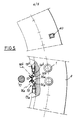
- Each pair of jacks 13 is formed by two jacks, respectively 13a, 13b (Fig. 5) opposite, located at the inner periphery of the support member 8, and fixed in a horizontal position.
- Each jack 13a and 13b has an outlet rod 14a and 14b, the free end of which is provided with a roller 15a and 15b which cooperates with the corresponding contact surface of the guide ramp 12.
- Each roller 15a and 15b is mounted on an axis, respectively 16a and 16b, parallel to the corresponding contact surface of said guide ramp 12.
- These means use at least two laser beams.
- the support member 8 comprises two laser generators 20 diametrically opposite which are intended to cooperate each with a receiving cell 30 mounted on the tank 3.
- Each laser generator 20 is located at the outer periphery of the support member 8 in which is formed a recess 21 used to accommodate a plate adjustment 22 fixed for example using screws 23.
- the adjustment plate 22 has tapped holes 24 into which are fastened fixing screws 25 blocking a sole 26 of the laser generator 20.
- Pressure screws 27 make it possible to adjust the position of said laser generator 20 along a vertical axis parallel to the axes of the threaded connecting elements 1.
- Each reception cell 30 is carried by a support plate 31 which comprises, for this purpose, a bore 32 of axis C in which said cell is fixed by means of screws 33 (Fig. 4). This reception cell 30 is therefore positioned along the axis C of the bore 32.
- the support plate 31 comprises two bores 34 distant from each other by a space corresponding to the spacing of two contiguous threads 4, that is to say of two threaded connecting elements 1.
- Each bore 34 of axis A ′ (FIG. 4) is radially open, which allows a partial encirclement of the corresponding thread 4 and consequently of the corresponding threaded connecting element 1, when the latter is screwed into said thread.
- each bore 34 is provided, projecting from the underside of the support plate 31, with a concentric centering 35 which is open in the same way as said bore.
- This centering 35 is placed in a counterbore 36 formed at the upper part of the corresponding threads 4.
- Each counterbore 36 is defined by an axis A which is also that of the corresponding thread 4 and which is positioned on a circumference concentric with the main axis of the tank 3.
- the axis C of said receiving cell 30 becomes the reference with respect to which the support member of the threaded connecting elements 1 is positioned.
- the device according to the invention comprises means for permanent control and for correcting the horizontality of the support member 8 of the threaded connecting elements 1.
- These means consist of at least two inclinometers 40 (Figs. 2 and 5) provided on the support member 8 and which, in dynamic phase, provide permanent control of the position of said support member which must be strictly horizontal.
- isonnivelage cylinders 41 (Figs. 1 and 2) are provided between each attachment point of the support member 8 with the handling means 9 of said support member.
- the entire device is managed by a programmable controller, not shown.
- the device operates as follows.
- the cover 2 is centered on the tank 3, then the support member 8 provided with all of the threaded connecting elements 1 is brought above said cover by means of handling means 9.
- the inclinometers 40 permanently check the horizontality of the support member 8 and the automaton programmable control, as a function of the information transmitted by said inclinometers the leveling cylinders 41 so as to maintain said support member 8 in a rigorous horizontal position.
- the programmable controller controls, on the one hand, the contacting of the rollers 15a and 15b of the jacks 13a and 13b of each pair of jacks 13 with the corresponding guide rails 12 and, on the other hand, the ignition laser generators 20 whose beams illuminate the targets formed by the reception cells 30.
- This programmable controller analyzes the signals transmitted by the reception cells 30 and controls the jacks 13a and 13b as a function of the signals received to make any corrections so as to bring the axes of the laser generators 20 into agreement with the axes of the reception cells 30 and align the threaded connection elements 1 with the corresponding threads 4.
- the presence of the cover 2, in place on the tank 3 serves as a fixed point allowing the support member to come to bear thereon so as to come and seek there the ideal position which makes it possible to execute the screwing operations in optimal conditions.
- the device according to the present invention therefore makes it possible to position simultaneously, with precision, several threaded connecting elements with respect to threads provided on a device and intended to receive said elements for fixing a part on this device.
- the device according to the invention applies not only to nuclear power plants, but to other sectors of the nuclear industry, to petroleum and pre-chemical installations, to mining installations, or even for the closure of turbines, hydraulic valves, pipes under pressure or valve body.
- the device according to the invention applies in the context of numerous industrial installations employing screwing elements.
Landscapes
- Engineering & Computer Science (AREA)
- Mechanical Engineering (AREA)
- Monitoring And Testing Of Nuclear Reactors (AREA)
- Connection Of Plates (AREA)
- Automatic Assembly (AREA)
- Pressure Vessels And Lids Thereof (AREA)
- Length Measuring Devices With Unspecified Measuring Means (AREA)
- Control Of Conveyors (AREA)
- Special Conveying (AREA)
- Machine Tool Sensing Apparatuses (AREA)
Applications Claiming Priority (2)
| Application Number | Priority Date | Filing Date | Title |
|---|---|---|---|
| FR9006465 | 1990-05-23 | ||
| FR9006465A FR2662473B1 (fr) | 1990-05-23 | 1990-05-23 | Dispositif de positionnement simultane de plusieurs elements de liaison filetees. |
Publications (2)
| Publication Number | Publication Date |
|---|---|
| EP0458680A1 true EP0458680A1 (de) | 1991-11-27 |
| EP0458680B1 EP0458680B1 (de) | 1994-03-30 |
Family
ID=9396899
Family Applications (1)
| Application Number | Title | Priority Date | Filing Date |
|---|---|---|---|
| EP91401261A Expired - Lifetime EP0458680B1 (de) | 1990-05-23 | 1991-05-15 | Vorrichtung zum gleichzeitigen Positionieren von mehreren Schraubverbindungselementen |
Country Status (12)
| Country | Link |
|---|---|
| US (1) | US5201112A (de) |
| EP (1) | EP0458680B1 (de) |
| JP (1) | JPH04282074A (de) |
| KR (1) | KR910019726A (de) |
| CS (1) | CS147891A3 (de) |
| DE (1) | DE69101517T2 (de) |
| ES (1) | ES2054459T3 (de) |
| FR (1) | FR2662473B1 (de) |
| HU (1) | HU210252B (de) |
| PL (1) | PL166013B1 (de) |
| RU (1) | RU2028921C1 (de) |
| ZA (1) | ZA913860B (de) |
Cited By (4)
| Publication number | Priority date | Publication date | Assignee | Title |
|---|---|---|---|---|
| EP0559390A3 (de) * | 1992-03-06 | 1993-09-22 | Daido Tokushuko Kabushiki Kaisha | Verfahren und Vorrichtung zum Annippeln einer neuen Elektrode an einer verbrauchten Elektrode in einem Elektroofen |
| CN103846641B (zh) * | 2012-11-29 | 2016-01-20 | 中国科学院沈阳自动化研究所 | 吊挂式卡车缓速器定子安装工装 |
| CN108994360A (zh) * | 2018-07-26 | 2018-12-14 | 湖北三江航天江北机械工程有限公司 | 异形曲面天线罩罩体与连接环的装配方法 |
| CN111660088A (zh) * | 2020-07-07 | 2020-09-15 | 盛勇 | 一种分体刹车碟的自动对孔装配设备 |
Families Citing this family (12)
| Publication number | Priority date | Publication date | Assignee | Title |
|---|---|---|---|---|
| US5774513A (en) * | 1997-01-14 | 1998-06-30 | Combustion Engineering, Inc. | Head area cable tray bridge |
| JP3546754B2 (ja) * | 1999-04-30 | 2004-07-28 | Jfeスチール株式会社 | 高炉の短期改修・建設方法およびリング状ブロックの上架装置 |
| US20040101084A1 (en) * | 2001-08-02 | 2004-05-27 | Advent Engineering Services, Inc. | Integrated head assembly for a nuclear reactor |
| DE102004005829B4 (de) * | 2004-02-06 | 2013-08-01 | Stiebel Eltron Gmbh & Co. Kg | Warmwasserspeicher mit einem verschraubten Kunststoffbehälter |
| KR20060042819A (ko) * | 2004-11-10 | 2006-05-15 | 엘지전자 주식회사 | 배터리의 보호회로 매입형 수지물 체결장치 |
| US8520794B2 (en) * | 2005-06-16 | 2013-08-27 | General Electric Company | Method and device for facilitating a uniform loading condition for a plurality of support members supporting a steam dryer in a nuclear reactor |
| US7567645B2 (en) * | 2005-07-19 | 2009-07-28 | Advent Engineering Services, Inc. | Modular integrated head assembly |
| CN106181828A (zh) * | 2016-08-24 | 2016-12-07 | 安徽柯力电气制造有限公司 | 一种用于自动拧螺丝机的装夹底座 |
| CN109990749B (zh) * | 2019-05-06 | 2024-02-09 | 广西玉柴机器股份有限公司 | 一种测量螺孔位置度辅助装置 |
| KR102674999B1 (ko) * | 2020-11-23 | 2024-06-13 | 주식회사 엘지에너지솔루션 | 볼팅 장치 |
| CN113001448B (zh) * | 2021-04-27 | 2022-09-02 | 广东鸿图武汉压铸有限公司 | 一种用于对工件三坐标测量的夹装装置 |
| CN119262588A (zh) * | 2024-11-15 | 2025-01-07 | 南京联衡电子有限公司 | 一种罐车罐口自助开关系统及其开关方法 |
Citations (1)
| Publication number | Priority date | Publication date | Assignee | Title |
|---|---|---|---|---|
| EP0220983A1 (de) * | 1985-10-29 | 1987-05-06 | Framatome | Verfahren und Vorrichtung zur Suche der optimalen Schraubposition für grosse Bolzen |
Family Cites Families (6)
| Publication number | Priority date | Publication date | Assignee | Title |
|---|---|---|---|---|
| US4223575A (en) * | 1977-11-21 | 1980-09-23 | Westinghouse Electric Corp. | Reactor vessel stud turnout tool |
| WO1980000672A1 (en) * | 1978-10-03 | 1980-04-17 | Pilgrim Eng Dev | Stud manipulating device |
| JPS5949148A (ja) * | 1982-09-14 | 1984-03-21 | Ricoh Co Ltd | 走査記録素子 |
| JPS59189082A (ja) * | 1983-03-26 | 1984-10-26 | Mazda Motor Corp | 部品組付け指示方法 |
| JPS59232737A (ja) * | 1983-06-13 | 1984-12-27 | Hitachi Denshi Ltd | 自動ねじ締め機 |
| US4873760A (en) * | 1986-12-29 | 1989-10-17 | Ishikawajima-Harima Heavy Industries Co., Ltd. | Vessel lid mounting and demounting apparatus |
-
1990
- 1990-05-23 FR FR9006465A patent/FR2662473B1/fr not_active Expired - Lifetime
-
1991
- 1991-05-15 ES ES91401261T patent/ES2054459T3/es not_active Expired - Lifetime
- 1991-05-15 EP EP91401261A patent/EP0458680B1/de not_active Expired - Lifetime
- 1991-05-15 DE DE69101517T patent/DE69101517T2/de not_active Expired - Fee Related
- 1991-05-20 CS CS911478A patent/CS147891A3/cs unknown
- 1991-05-22 ZA ZA913860A patent/ZA913860B/xx unknown
- 1991-05-22 RU SU914895513A patent/RU2028921C1/ru active
- 1991-05-22 KR KR1019910008211A patent/KR910019726A/ko not_active Withdrawn
- 1991-05-22 PL PL91290359A patent/PL166013B1/pl unknown
- 1991-05-23 HU HU911739A patent/HU210252B/hu not_active IP Right Cessation
- 1991-05-23 US US07/704,388 patent/US5201112A/en not_active Expired - Fee Related
- 1991-05-23 JP JP3147921A patent/JPH04282074A/ja not_active Withdrawn
Patent Citations (1)
| Publication number | Priority date | Publication date | Assignee | Title |
|---|---|---|---|---|
| EP0220983A1 (de) * | 1985-10-29 | 1987-05-06 | Framatome | Verfahren und Vorrichtung zur Suche der optimalen Schraubposition für grosse Bolzen |
Non-Patent Citations (2)
| Title |
|---|
| PATENT ABSTRACTS OF JAPAN vol. 9, no. 111 (M-379)(1834) 15 mai 1985, & JP-A-59 232737 (HITACHI DENSHI) 27 décembre 84, * |
| PATENT ABSTRACTS OF JAPAN vol. 9, no. 55 (M-362)(1778) 09 mars 1985, & JP-A-59 189082 (MAZDA) 26 octobre 1984, * |
Cited By (5)
| Publication number | Priority date | Publication date | Assignee | Title |
|---|---|---|---|---|
| EP0559390A3 (de) * | 1992-03-06 | 1993-09-22 | Daido Tokushuko Kabushiki Kaisha | Verfahren und Vorrichtung zum Annippeln einer neuen Elektrode an einer verbrauchten Elektrode in einem Elektroofen |
| CN103846641B (zh) * | 2012-11-29 | 2016-01-20 | 中国科学院沈阳自动化研究所 | 吊挂式卡车缓速器定子安装工装 |
| CN108994360A (zh) * | 2018-07-26 | 2018-12-14 | 湖北三江航天江北机械工程有限公司 | 异形曲面天线罩罩体与连接环的装配方法 |
| CN108994360B (zh) * | 2018-07-26 | 2019-10-29 | 湖北三江航天江北机械工程有限公司 | 异形曲面天线罩罩体与连接环的装配方法 |
| CN111660088A (zh) * | 2020-07-07 | 2020-09-15 | 盛勇 | 一种分体刹车碟的自动对孔装配设备 |
Also Published As
| Publication number | Publication date |
|---|---|
| DE69101517D1 (de) | 1994-05-05 |
| KR910019726A (ko) | 1991-12-19 |
| RU2028921C1 (ru) | 1995-02-20 |
| DE69101517T2 (de) | 1994-07-14 |
| PL166013B1 (pl) | 1995-03-31 |
| CS147891A3 (en) | 1992-02-19 |
| FR2662473B1 (fr) | 1992-09-11 |
| EP0458680B1 (de) | 1994-03-30 |
| HU911739D0 (en) | 1991-12-30 |
| ES2054459T3 (es) | 1994-08-01 |
| ZA913860B (en) | 1992-12-30 |
| HU210252B (en) | 1995-03-28 |
| HUT58584A (en) | 1992-03-30 |
| FR2662473A1 (fr) | 1991-11-29 |
| JPH04282074A (ja) | 1992-10-07 |
| US5201112A (en) | 1993-04-13 |
Similar Documents
| Publication | Publication Date | Title |
|---|---|---|
| EP0458680B1 (de) | Vorrichtung zum gleichzeitigen Positionieren von mehreren Schraubverbindungselementen | |
| FR2673447A1 (fr) | Broche d'alignement de deux elements et dispositif de centrage d'un couvercle sur une cuve mettant en óoeuvre ce type de broches. | |
| NO830285L (no) | Anordning ved ventil. | |
| EP0242273B1 (de) | Greifvorrichtung zum Spannen von Bolzen | |
| FR3088559B1 (fr) | Dispositif de dépose d’une fixation installée dans un perçage | |
| US2689102A (en) | Leveling saddle assembly | |
| FR2740105A1 (fr) | Dispositif de pilotage d'un vehicule spatial par vannage de gaz | |
| JP3170373B2 (ja) | ねじ引張装置 | |
| EP0219412B1 (de) | Vorrichtung zum Verriegeln eines Führungsringes auf einer mit einer Öffnung versehenen Platte und Anwendung für ein Führungsrohr eines Kernreaktors | |
| EP0222625B2 (de) | Spannvorrichtung zum Schrauben und Entschrauben von Bolzen oder Stiften | |
| RU2319883C2 (ru) | Клапан сброса давления с улучшенной ремонтопригодностью | |
| EP0467755A1 (de) | Vorrichtung für schwingungsneutralisierendes Festsetzen von Wärmetauscherrohren | |
| EP0701260A1 (de) | Dichtvorrichtung für ein Innerhalb eines Adapters durch den Deckel eines Kernreaktorgefässes führendes Instrumentenführungsrohr | |
| BE898301A (fr) | Dispositif de mise en tension de barres de précontrainte et de détermination de cette tension. | |
| NO143241B (no) | Laasering. | |
| EP0220983A1 (de) | Verfahren und Vorrichtung zur Suche der optimalen Schraubposition für grosse Bolzen | |
| JP4315851B2 (ja) | バルブ修理治具及びその修理方法 | |
| US2694407A (en) | Safety device for fluid pressure pipe lines | |
| FR2642217A1 (fr) | Dispositif d'etancheite pour une colonne d'instrumentation traversant le couvercle d'une cuve de reacteur nucleaire a eau sous pression | |
| JP2559130Y2 (ja) | パッキン押さえ治具 | |
| US4040611A (en) | Device for clamping the base plate of a steel refining converter | |
| CN102095030B (zh) | 计量表用连接螺母的不正当拆卸的防止装置 | |
| EP0243218B1 (de) | Positioniergerät zum Schrauben und Losschrauben einer Mutter | |
| EP3715646B1 (de) | Abnehmbare befestigungsvorrichtung | |
| EP0365374A1 (de) | Vorrichtung zur Handhabung einer Ausdehnungsmaschine für verschraubte Verbindungselemente |
Legal Events
| Date | Code | Title | Description |
|---|---|---|---|
| PUAI | Public reference made under article 153(3) epc to a published international application that has entered the european phase |
Free format text: ORIGINAL CODE: 0009012 |
|
| 17P | Request for examination filed |
Effective date: 19910930 |
|
| AK | Designated contracting states |
Kind code of ref document: A1 Designated state(s): BE CH DE ES GB IT LI NL SE |
|
| 17Q | First examination report despatched |
Effective date: 19930209 |
|
| GRAA | (expected) grant |
Free format text: ORIGINAL CODE: 0009210 |
|
| AK | Designated contracting states |
Kind code of ref document: B1 Designated state(s): BE CH DE ES GB IT LI NL SE |
|
| PG25 | Lapsed in a contracting state [announced via postgrant information from national office to epo] |
Ref country code: IT Free format text: LAPSE BECAUSE OF FAILURE TO SUBMIT A TRANSLATION OF THE DESCRIPTION OR TO PAY THE FEE WITHIN THE PRE;WARNING: LAPSES OF ITALIAN PATENTS WITH EFFECTIVE DATE BEFORE 2007 MAY HAVE OCCURRED AT ANY TIME BEFORE 2007. THE CORRECT EFFECTIVE DATE MAY BE DIFFERENT FROM THE ONE RECORDED.SCRIBED TIME-LIMIT Effective date: 19940330 Ref country code: SE Free format text: THE PATENT HAS BEEN ANNULLED BY A DECISION OF A NATIONAL AUTHORITY Effective date: 19940330 Ref country code: NL Effective date: 19940330 Ref country code: GB Effective date: 19940330 |
|
| PGFP | Annual fee paid to national office [announced via postgrant information from national office to epo] |
Ref country code: DE Payment date: 19940418 Year of fee payment: 4 |
|
| PGFP | Annual fee paid to national office [announced via postgrant information from national office to epo] |
Ref country code: CH Payment date: 19940419 Year of fee payment: 4 |
|
| REF | Corresponds to: |
Ref document number: 69101517 Country of ref document: DE Date of ref document: 19940505 |
|
| PGFP | Annual fee paid to national office [announced via postgrant information from national office to epo] |
Ref country code: ES Payment date: 19940518 Year of fee payment: 4 |
|
| PGFP | Annual fee paid to national office [announced via postgrant information from national office to epo] |
Ref country code: BE Payment date: 19940530 Year of fee payment: 4 |
|
| REG | Reference to a national code |
Ref country code: ES Ref legal event code: FG2A Ref document number: 2054459 Country of ref document: ES Kind code of ref document: T3 |
|
| NLV1 | Nl: lapsed or annulled due to failure to fulfill the requirements of art. 29p and 29m of the patents act | ||
| GBV | Gb: ep patent (uk) treated as always having been void in accordance with gb section 77(7)/1977 [no translation filed] |
Effective date: 19940330 |
|
| PLBE | No opposition filed within time limit |
Free format text: ORIGINAL CODE: 0009261 |
|
| STAA | Information on the status of an ep patent application or granted ep patent |
Free format text: STATUS: NO OPPOSITION FILED WITHIN TIME LIMIT |
|
| 26N | No opposition filed | ||
| PG25 | Lapsed in a contracting state [announced via postgrant information from national office to epo] |
Ref country code: ES Free format text: LAPSE BECAUSE OF NON-PAYMENT OF DUE FEES Effective date: 19950516 |
|
| PG25 | Lapsed in a contracting state [announced via postgrant information from national office to epo] |
Ref country code: LI Effective date: 19950531 Ref country code: CH Effective date: 19950531 Ref country code: BE Effective date: 19950531 |
|
| BERE | Be: lapsed |
Owner name: FRAMATOME Effective date: 19950531 |
|
| REG | Reference to a national code |
Ref country code: CH Ref legal event code: PL |
|
| PG25 | Lapsed in a contracting state [announced via postgrant information from national office to epo] |
Ref country code: DE Effective date: 19960201 |
|
| REG | Reference to a national code |
Ref country code: ES Ref legal event code: FD2A Effective date: 19990503 |