EP0458848B1 - Vorrichtung und verfahren für exothermische reaktionen - Google Patents
Vorrichtung und verfahren für exothermische reaktionen Download PDFInfo
- Publication number
- EP0458848B1 EP0458848B1 EP90903328A EP90903328A EP0458848B1 EP 0458848 B1 EP0458848 B1 EP 0458848B1 EP 90903328 A EP90903328 A EP 90903328A EP 90903328 A EP90903328 A EP 90903328A EP 0458848 B1 EP0458848 B1 EP 0458848B1
- Authority
- EP
- European Patent Office
- Prior art keywords
- cooling
- gas
- tube
- catalyst bed
- tubes
- Prior art date
- Legal status (The legal status is an assumption and is not a legal conclusion. Google has not performed a legal analysis and makes no representation as to the accuracy of the status listed.)
- Expired - Lifetime
Links
Images

Classifications
-
- B—PERFORMING OPERATIONS; TRANSPORTING
- B01—PHYSICAL OR CHEMICAL PROCESSES OR APPARATUS IN GENERAL
- B01J—CHEMICAL OR PHYSICAL PROCESSES, e.g. CATALYSIS OR COLLOID CHEMISTRY; THEIR RELEVANT APPARATUS
- B01J8/00—Chemical or physical processes in general, conducted in the presence of fluids and solid particles; Apparatus for such processes
- B01J8/02—Chemical or physical processes in general, conducted in the presence of fluids and solid particles; Apparatus for such processes with stationary particles, e.g. in fixed beds
- B01J8/0278—Feeding reactive fluids
-
- B—PERFORMING OPERATIONS; TRANSPORTING
- B01—PHYSICAL OR CHEMICAL PROCESSES OR APPARATUS IN GENERAL
- B01J—CHEMICAL OR PHYSICAL PROCESSES, e.g. CATALYSIS OR COLLOID CHEMISTRY; THEIR RELEVANT APPARATUS
- B01J8/00—Chemical or physical processes in general, conducted in the presence of fluids and solid particles; Apparatus for such processes
- B01J8/0005—Catalytic processes under superatmospheric pressure
-
- B—PERFORMING OPERATIONS; TRANSPORTING
- B01—PHYSICAL OR CHEMICAL PROCESSES OR APPARATUS IN GENERAL
- B01J—CHEMICAL OR PHYSICAL PROCESSES, e.g. CATALYSIS OR COLLOID CHEMISTRY; THEIR RELEVANT APPARATUS
- B01J8/00—Chemical or physical processes in general, conducted in the presence of fluids and solid particles; Apparatus for such processes
- B01J8/02—Chemical or physical processes in general, conducted in the presence of fluids and solid particles; Apparatus for such processes with stationary particles, e.g. in fixed beds
- B01J8/0207—Chemical or physical processes in general, conducted in the presence of fluids and solid particles; Apparatus for such processes with stationary particles, e.g. in fixed beds the fluid flow within the bed being predominantly horizontal
- B01J8/0214—Chemical or physical processes in general, conducted in the presence of fluids and solid particles; Apparatus for such processes with stationary particles, e.g. in fixed beds the fluid flow within the bed being predominantly horizontal in a cylindrical annular shaped bed
-
- B—PERFORMING OPERATIONS; TRANSPORTING
- B01—PHYSICAL OR CHEMICAL PROCESSES OR APPARATUS IN GENERAL
- B01J—CHEMICAL OR PHYSICAL PROCESSES, e.g. CATALYSIS OR COLLOID CHEMISTRY; THEIR RELEVANT APPARATUS
- B01J8/00—Chemical or physical processes in general, conducted in the presence of fluids and solid particles; Apparatus for such processes
- B01J8/02—Chemical or physical processes in general, conducted in the presence of fluids and solid particles; Apparatus for such processes with stationary particles, e.g. in fixed beds
- B01J8/0285—Heating or cooling the reactor
-
- C—CHEMISTRY; METALLURGY
- C01—INORGANIC CHEMISTRY
- C01C—AMMONIA; CYANOGEN; COMPOUNDS THEREOF
- C01C1/00—Ammonia; Compounds thereof
- C01C1/02—Preparation, purification or separation of ammonia
- C01C1/04—Preparation of ammonia by synthesis
- C01C1/0405—Preparation of ammonia by synthesis from N2 and H2 in presence of a catalyst
- C01C1/0417—Preparation of ammonia by synthesis from N2 and H2 in presence of a catalyst characterised by the synthesis reactor, e.g. arrangement of catalyst beds and heat exchangers in the reactor
-
- C—CHEMISTRY; METALLURGY
- C07—ORGANIC CHEMISTRY
- C07C—ACYCLIC OR CARBOCYCLIC COMPOUNDS
- C07C29/00—Preparation of compounds having hydroxy or O-metal groups bound to a carbon atom not belonging to a six-membered aromatic ring
- C07C29/15—Preparation of compounds having hydroxy or O-metal groups bound to a carbon atom not belonging to a six-membered aromatic ring by reduction of oxides of carbon exclusively
- C07C29/151—Preparation of compounds having hydroxy or O-metal groups bound to a carbon atom not belonging to a six-membered aromatic ring by reduction of oxides of carbon exclusively with hydrogen or hydrogen-containing gases
- C07C29/152—Preparation of compounds having hydroxy or O-metal groups bound to a carbon atom not belonging to a six-membered aromatic ring by reduction of oxides of carbon exclusively with hydrogen or hydrogen-containing gases characterised by the reactor used
-
- F—MECHANICAL ENGINEERING; LIGHTING; HEATING; WEAPONS; BLASTING
- F28—HEAT EXCHANGE IN GENERAL
- F28D—HEAT-EXCHANGE APPARATUS, NOT PROVIDED FOR IN ANOTHER SUBCLASS, IN WHICH THE HEAT-EXCHANGE MEDIA DO NOT COME INTO DIRECT CONTACT
- F28D7/00—Heat-exchange apparatus having stationary tubular conduit assemblies for both heat-exchange media, the media being in contact with different sides of a conduit wall
- F28D7/16—Heat-exchange apparatus having stationary tubular conduit assemblies for both heat-exchange media, the media being in contact with different sides of a conduit wall the conduits being arranged in parallel spaced relation
-
- F—MECHANICAL ENGINEERING; LIGHTING; HEATING; WEAPONS; BLASTING
- F28—HEAT EXCHANGE IN GENERAL
- F28F—DETAILS OF HEAT-EXCHANGE AND HEAT-TRANSFER APPARATUS, OF GENERAL APPLICATION
- F28F9/00—Casings; Header boxes; Auxiliary supports for elements; Auxiliary members within casings
- F28F9/02—Header boxes; End plates
- F28F9/026—Header boxes; End plates with static flow control means, e.g. with means for uniformly distributing heat exchange media into conduits
- F28F9/027—Header boxes; End plates with static flow control means, e.g. with means for uniformly distributing heat exchange media into conduits in the form of distribution pipes
- F28F9/0273—Header boxes; End plates with static flow control means, e.g. with means for uniformly distributing heat exchange media into conduits in the form of distribution pipes with multiple holes
-
- B—PERFORMING OPERATIONS; TRANSPORTING
- B01—PHYSICAL OR CHEMICAL PROCESSES OR APPARATUS IN GENERAL
- B01J—CHEMICAL OR PHYSICAL PROCESSES, e.g. CATALYSIS OR COLLOID CHEMISTRY; THEIR RELEVANT APPARATUS
- B01J2208/00—Processes carried out in the presence of solid particles; Reactors therefor
- B01J2208/00008—Controlling the process
- B01J2208/00017—Controlling the temperature
- B01J2208/00106—Controlling the temperature by indirect heat exchange
- B01J2208/00115—Controlling the temperature by indirect heat exchange with heat exchange elements inside the bed of solid particles
- B01J2208/00132—Tubes
-
- Y—GENERAL TAGGING OF NEW TECHNOLOGICAL DEVELOPMENTS; GENERAL TAGGING OF CROSS-SECTIONAL TECHNOLOGIES SPANNING OVER SEVERAL SECTIONS OF THE IPC; TECHNICAL SUBJECTS COVERED BY FORMER USPC CROSS-REFERENCE ART COLLECTIONS [XRACs] AND DIGESTS
- Y02—TECHNOLOGIES OR APPLICATIONS FOR MITIGATION OR ADAPTATION AGAINST CLIMATE CHANGE
- Y02P—CLIMATE CHANGE MITIGATION TECHNOLOGIES IN THE PRODUCTION OR PROCESSING OF GOODS
- Y02P20/00—Technologies relating to chemical industry
- Y02P20/50—Improvements relating to the production of bulk chemicals
- Y02P20/52—Improvements relating to the production of bulk chemicals using catalysts, e.g. selective catalysts
Definitions
- the present invention relates to a cooled reactor for carrying out catalytic reactions.
- This reactor is of the kind comprising a cylindrical pressure shell, at least one tube sheet, means for passing the gaseous raw materials as a synthesis gas in a substantially radial direction through at least one catalyst bed provided with one or more cooling tubes for the indirect cooling of reacting gas, each cooling tube having a lower inlet end, an upper outlet end and an outer heat exchange wall.
- the invention also relates to a process for carrying out exothermic reactions of gaseous raw materials in one or more catalyst beds in the reactor according to the invention.
- the temperature profile in the catalyst layer during exothermic reactions depends not only on the rate of the evolution of heat of reaction but also on the method of removing heat from the catalyst bed to avoid excessive elevation of the temperature of the reacting gaseous material and the catalyst.
- Substantially three different methods are used for removing the heat of reaction from the catalyst bed: direct cooling by mixing with a cold feed gas; indirect cooling by heat exchangers; and using cooling tubes in the catalyst bed.
- a method which is frequently used at present for removing excessive heat is heat exchange between a high temperature gas leaving the catalyst layer and a cold feed (synthesis) gas, thereby elevating the temperature of the feed gas to a level necessary for initiating the reaction.
- Gas-gas heat exchanging units are thereby usually disposed centrally in or after one or more catalyst beds. However, in this manner only minor parts of the catalyst bed will be at optimum temperature; and consequently, by this method large parts of the catalyst bed suffer from insufficient temperature control.
- reaction vessels in the prior art which are provided with cooling tubes which extend through different regions of the catalyst bed. Thereby excessive heat is transferred to a cold feed gas or to an external cooling medium.
- the gas or medium which enters the cooling tubes extending through the catalyst bed absorbs the heat evolved in the reaction.
- the temperature difference between the reacting gas and the cooling tubes will increase and the temperature will thereby in some regions of the catalyst bed exceed the temperature for a maximum reaction rate. Therefore, the temperature control is sluggish and temperature oscillations around the cooling tubes dampen out very slowly.
- Reactors based on such a design are the known counter-current axial flow ammonia converter of the Tennessee Valley Authority type (TVA) as described in Industr. Engn. Chem. 45 (1953), 1242 and the co-current axial flow ammonia converter of the Nitrogen Engineering Corporation, mentioned in Br. Chem. Eng. 8 (1963), 171.
- TVA Tennessee Valley Authority type
- Cooling of a radial flow reactor constitutes a special problem: in order to carry out the cooling in a favourable way, the temperature of the cooling surface has to be kept constant throughout the height of the catalyst bed although it may vary with the radial position in the bed.
- a method disclosed in US Patent Specification No. 4,321,234 for removing the heat of reaction in a radial flow reactor is to evaporate a liquid under a convenient pressure by passing a liquid cooling medium through cooling tubes.
- a cooling medium in the form of a rising stream is introduced and distributed via a system of distribution tubes into a number of second distribution tubes and then to a large number of cooling tubes connected to the second distribution tubes controlling the temperature inside the catalyst bed.
- Another disadvantage of the method disclosed in the above US Patent is the demand of external preheating of the feed gas to a temperature required for initiating the reaction in the catalyst bed and adjusting the boiling point of the cooling medium to a level which is just below or about the temperature inside the catalyst bed and which is determined by the kind of the conversion reaction.
- an object of the present invention to provide an apparatus wherein gaseous raw materials are reacted exothermically by passing a stream of the gaseous raw material in a radial direction through a catalyst bed under optimal temperature control achieved by cooling tubes preferably arranged in elongated cooling zones for a gaseous cooling medium disposed axially throughout the catalyst bed without the known complications.
- each cooling tube consist of a fluid-tight heat exchanging outer tube coaxial with and surrounding an inner tube fitted in a fluid-tight manner to the inlet end of the cooling tube and thereby defining an annular space between the outer and inner tubes, the annular space being open at the outlet end of the cooling tubes, said inner tube being open at its inlet end and closed at the outlet end and being provided in its wall with a plurality of perforations throughout its length for directing a stream of cooling gas to the annular space and along the heat exchanging outer wall of the cooling tube.
- the temperature distribution in the catalyst bed is optimized by arranging the cooling tubes in a number of coaxial cooling zones containing staggered rows of cooling tubes, in order to obtain regions with adiabatic reaction and regions with cooling in the catalyst bed.
- the inner, perforated tubes of the cooling tubes may be slightly conical.
- the invention also relates to an improved process for exothermic reactions of gaseous raw materials in one or more catalyst beds in a reactor as described.
- the gaseous raw materials are passed through at least one catalyst bed containing axially arranged cooling tubes, and passing a cooling gas through the perforated inner tubes of the cooling tubes to the annular space and along the heat exchanging outer wall of the outer tube of the cooling tubes in order to remove excessive heat of reaction from the catalyst bed by indirect heat exchange with the cooling gas.
- the annular space inside the cooling tubes is kept at a constant temperature between the temperature of the surrounding catalyst and the temperature of the incoming synthesis gas by passing the gaseous raw materials in a substantially radial direction through the catalyst bed.
- the cooling gas may advantageously contain the gaseous raw materials (i.e. synthesis gas) which are preheated by indirect heat exchange with reacting gas in the catalyst bed to a temperature necessary for maintaining the conversion of the gaseous raw materials in the catalyst bed to a stream of product gas.
- gaseous raw materials i.e. synthesis gas
- the reaction yield is improved, which makes it possible to reduce the amount of the catalyst by about 20% compared to known radial flow reactors, thus saving necessary capital costs at a rate of about 25%.
- the reactor shown schematically in Fig. 1 has a pressure shell 10 which constitutes the outer surface of the reactor.
- the reactor shell is provided with an inlet 12 for incoming gas and an outlet 14 for product gas.
- a central pipe 16 is connected to the outlet 14 in the conventional manner.
- the central pipe 16, which serves at receiving reacted gas (product gas) from a catalyst bed 20, has a perforated wall 18 extending through the catalyst bed 20 and a gas-tight wall 22 at its upper end, extending from the gastight end 26 into the upper part of the catalyst bed 20.
- the lower end of the central pipe 16 has a gastight wall 24 extending from the bottom of the catalyst bed 20 to the open end 28 of the central pipe 16 adjacent the outlet end 14.
- a closable further inlet opening 42 for gas may be present near the top of the reactor.
- each cooling tube 38 consist of two concentric tubes, an inner tube 2 and an outer tube 4, defining an annular space 6 between them.
- the inner tube 2 is open at the lower, inlet end 2a and closed at the upper, outlet end 2b and has a plurality of openings 8 distributed over its length for directing jets of incoming cooling gas into the annular space 6.
- the lower edge 6a of the inner tube 2 is bent towards the wall of the outer tube 4 and fitted to the bottom edge of the outer tube 4, thus providing a gastight lip 6a connecting the walls of the cooling tube 38.
- the outer tube 4 is fitted into the bottom tube sheet 30 and the cover sheet 36 whereby the annular space 6 is closed at its lower end 6a and open at its upper end 6b.
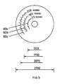
- the cooling tubes 38 which optionally may be distributed uniformly in the catalyst bed, are arranged in the catalyst bed 20 in a number of cooling zones 60a, 60b, 60c.... as schematically shown in Fig. 5.
- the cooling zones 60a, 60b, 60c...., each containing a convenient number of cooling tubes 38, are distributed coaxially throughout the catalyst bed to obtain regions with adiabatic reaction and regions with cooling in the catalyst bed 20.
- a stream of incoming gas which is to serve as synthesis gas as well as cooling gas, is introduced via inlet 12 into a space 40 adjacent the lower part of the pressure shell 10 and confined by a cover plate 32 of the gas distribution unit 34 and the bottom tube sheet 30, which is fitted to the inner circumferential position of the pressure shell 10.
- the slightly conical inner tube 2 is provided with the several openings 8 and supplies a uniform gas flow to the annular space 6 with constant velocity along the heat exchanging wall 7 of the outer tube 4.
- the gas leaves the annular space of the cooling tubes 38 at the upper end 6b and becomes effectively the reacting synthesis gas.
- the temperature of the catalyst bed will be constant adjacent and along the entire outer heat exchanging wall 7 of the cooling tubes 38, which by constant heat transmission ensures a constant temperature inside the annular space 6.
- the gas is introduced into the gas distribution unit 34 after leaving the cooling tubes 38 and uniformly distributed to the catalyst bed 20.
- the reacting gas passes in radial direction and substantially at right angles to the cooling tubes from the gas distribution unit to the central pipe 16, thereby passing regions with adiabatic reaction and regions with cooling in the cooling zones 60a, 60b, 60c... .
- the product stream of synthesis gas is passed from the central pipe 16 to the outlet 14.
- the invention as described hereinbefore is generally applicable to catalytic reactions where gaseous raw materials are reacted exothermically to form gaseous products.
- Typical catalytic reactions to which the invention is applicable are the reaction between carbon oxides and hydrogen to methanol, oxosyntheses, and the catalytic conversion of hydrogen and nitrogen to ammonia.
- a modelling procedure is utilized for an ammonia plant simulated as a number of back-mix reactors in series with a poduction capacity of 1000 metric tons per day by using the process and the reactor of the invention as shown in Figs. 1 to 5.
- the catalyst used in the modelling procedure is the conventional ammonia catalyst KM 1.5-3 supplied by Haldor Tops ⁇ e A/S, Lyngby, Denmark, having a particle size of 1.5-3 mm and a density of 2700 kg/m3.
- the catalyst bed 20 is set to a total volume of 46 m3 and a height of 10 m.
- the composition of the incoming gas which functions both as cooling gas and synthesis gas, and the composition of the product stream and further data related to Example 1 are shown in Tables I to III hereinafter.
- the reactor is operated at a pressure of 140 kg/cm2g.
- a process stream of synthesis gas of 500,000 Nm3/h having an inlet temperature of 266°C is introduced via the inlet 12 and the tube sheet 30 at the bottom of the reactor shell, which serves to distribute the incoming gas to the lower ends 2a of the inner tubes 2 of the cooling tubes 38.
- These are axially arranged as two staggered rows in each of three coaxial cooling zones 60a, 60b, 60c comprising 72 tubes, 183 tubes, and 226 tubes, respectively.
- the gas adopts a constant temperature between the temperature of the incoming gas and the temperature of the reacting gas.
- the process stream of reacting gas is forced via the gas distribution unit 34 into a substantially radial direction through the catalyst bed 20.
- the ammonia concentration in the process stream is increased from 4.1 to 16.6 vol% by continuously passing the stream through adiabatic and cooling regions.
- the product stream formed from the synthesis gas is then received in the central pipe 16 and passed to the outlet 14 at a temperature of about 450°C.
- Example 2 The reactor and process of Example 2 are the same as described in Example 1 except for the following features: The volume of the catalyst is raised from 46 to 56 m3 and the flow of synthesis gas is decreased to 480,000 Nm3/h.
- the number of cooling tubes 38 in the first cooling zone 60c is increased from 226 as in Example 1 to 348, arranged in three staggered rows instead of two, and in the third cooling zone 60a from 72 to 125.
- the yield of ammonia is hereby improved from 16.6 to 17.4 vol% though the gas flow is reduced by 4%.
- the outcoming product gas has a temperature of 430°C.
- the catalyst volume is raised to 128 m3 and the flow of synthesis gas is decreased to 380,000 Nm3/h.
- the amount of ammonia in the product gas is further improved to 21.8 vol%.
- the temperature of the outcoming product gas is 392°C.
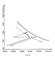
- Fig. 6 shows the concentration-temperature profile of the process according to Example 1 in comparison with the profile of a simulated process obtained in the known two-bed radial flow converter S-200 as described in US Patent Specification No. 4,181,701, equipped with a centrally mounted heat exchanger in the first catalyst bed.
- curve B represents the thermodynamic equilibrium concentration at the conditions for the process and at the synthesis gas composition used in Example 1 (cf. Table I). Curve A illustrates an approach to this equilibrium by 10°C, which is a reasonable approach obtainable in practice.
- Curves C and D represent changes occurring in the temperature and the ammonia concentration of the process stream of synthesis gas during its passage through the catalyst bed for the ammonia synthesis process.
- the concentration-temperature profile for the process of Example 1 according to the invention is represented in Fig. 6 by the solid line C whereas the dotted line D represents the course of the process obtained in the S-200 converter. All the process parameters used in the S-200 reactor are equal to those described in Example 1, except the amount of catalyst, which is 56 m3 in the S-200 reactor instead of 46 m3 used in the reactor according to the invention.
- Both reactors are simulated as a number of back-mix reactors connected in series. As seen from Fig. 6, replacement of the S-200 heat exchanger by cooling tubes mounted in several cooling zones compared with the known reactor causes a remarkable dampening of temperature oscillation around the optimum reaction-temperature curve A.
- the amount of ammonia in the product stream is the same in both cases though the catalyst volume in the reactor of the present invention is reduced by nearly 20%.
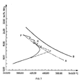
- Fig. 7 The effect on the temperature-ammonia concentration profile caused by increasing the number of cooling tubes in the reactor according to the invention is further shown in Fig. 7, in which curves A and B are the same as in Fig. 6.
- a good approach to the optimum reaction curve A is represented by the dotted line E, which represents the process described in Example 2 (altogether 656 tubes).
- the solid line F representing Example 3
- the coefficient of heat transmission h y at the outside of the cooling tubes is calculated according to standard formulas for crossflow inside a bundle of tubes when considering the reduced flow area caused by the catalyst particles.
- the invention is expected to be of great importance in the ammonia industry where the improved levelling out of the temperature difference in the catalyst bed will improve the yields of ammonia with a given amount of catalyst and hence reduce the costs. Similar results can be expected in other industrial exothermic reactions in which gaseous products are manufactured from gaseous synthesis gases, e.g. the Fischer-Tropsch synthesis and synthesis of methanol.
Landscapes
- Chemical & Material Sciences (AREA)
- Organic Chemistry (AREA)
- Chemical Kinetics & Catalysis (AREA)
- Engineering & Computer Science (AREA)
- Physics & Mathematics (AREA)
- General Engineering & Computer Science (AREA)
- Thermal Sciences (AREA)
- Mechanical Engineering (AREA)
- Inorganic Chemistry (AREA)
- Analytical Chemistry (AREA)
- Fluid Mechanics (AREA)
- Devices And Processes Conducted In The Presence Of Fluids And Solid Particles (AREA)
- Organic Low-Molecular-Weight Compounds And Preparation Thereof (AREA)
- Saccharide Compounds (AREA)
Claims (7)
- Gekühlter Reaktor zur Durchführung exothermer katalytischer Reaktionen von gasförmigen Rohmaterialien, umfassend eine zylindrische Druckschale (10), mindestens eine Rohrplatte (30), Mittel zum Leiten der gasförmigen Rohmaterialien als Synthesegas in im wesentlichen radialer Richtung durch zumindest ein mit einer oder mehreren Kühlrohren (38) versehenes Katalysatorbett (20) zum indirekten Abkühlen von reagierendem Gas, wobei jedes Kühlrohr eine niedere Einlasseite, eine obere Auslasseite und eine äussere Wärmeaustauschwand (7) aufweist, dadurch gekennzeichnet, dass jedes Kühlrohr (38) aus einem fluidumdichten, wärmeaustauschendem Aussenrohr (4) besteht, das mit einem auf der Einlassseite des Kühlrohres in fluidumdichter Weise befestigten Innenrohr (2) koaxial ist und dieses umschliesst, und dadurch einen ringförmigen Raum (6) zwischen den Aussen- und Innenrohren (4, 2) abgrenzt, wobei bei der ringförmige Raum bei der Ausgangsseite (6b) der Kühlrohre (38) offen ist, und das Innenrohr (2) auf seiner Einlasseite (2a) offen und seiner Auslasseite (6b) geschlossen ist und in seiner Wand der Länge entlang mit einer Mehrzahl von Perforationen (8) zum Leiten des Stroms von Kühlgas zu dem ringförmigen Raum (6) und entlang der wärmeaustauschenden Aussenwand (7) des Kühlrohres (38) ausgestattet ist.
- Gekühlter Reaktor nach Anspruch 1, dadurch gekennzeichnet, dass die Kühlrohre (38) im Katalysatorbett (20) in koaxialen Kühlzonen (60a, 60b, 60c..) angeordnet sind, die gestaffelte Reihen von Kühlrohren (38) enthalten.
- Gekühlter Reaktor nach Anspruch 1 oder 2, dadurch gekennzeichnet, dass das innere, perforierte Rohr (2) des Kühlrohres (38) konisch ausgebildet ist.
- Verfahren zur exothermen Reaktion gasförmiger Rohmaterialien in einem oder mehreren Katalysatorbetten (20) in einem Reaktor nach Anspruch 1, dadurch gekennzeichnet, dass die gasförmigen Rohmaterialien durch zumindest ein Kühlrohre (38) enthaltendes Katalysatorbett (20) geleitet werden, und dass ein Kühlgas durch die perforierten Innenrohre (2) der Kühlrohre zu dem ringförmigen Raum (6) und entlang der wärmeaustauschenden Aussenwand (7) des Aussenrohres (4) der Kühlrohre (38) geleitet wird, um durch indirekten Wärmeaustausch mit dem Kühlgas überschüssige Reaktionswärme vom Katalysatorbett (20) zu entfernen.
- Verfahren nach Anspruch 4, dadurch gekennzeichnet, dass die gasförmigen Rohmaterialien in im wesentlichen radialer Richtung durch das Katalysatorbett (20) geleitet werden, um die Temperatur in dem ringförmigen Raum (6) innerhalb der Kühlrohre (38) auf einem gleichbleibenden Niveau, das zwischen der Temperatur des umgebenden Katalysatorbetts (20) und der Temperatur des zugeleiteten Synthesegases liegt, zu halten.
- Verfahren nach Anspruch 4, gekennzeichnet durch die Benutzung eines Reaktors, in welchem die Kühlrohre (38) in mindestens einem Katalysatorbett in koaxialen Kühlzonen (60a, 60b, 60c..) mit gestaffelten Reihen von Kühlrohren (38) angeordnet sind.
- Verfahren nach Anspruch 4, dadurch gekennzeichnet, dass das Kühlgas die gasförmigen Rohmaterialien umfasst, die durch einen indirekten Wärmeaustausch mit Reaktionsgas im Katalysatorbett auf eine Temperatur erhitzt werden, die zur Aufrechterhaltung des Umsatzes der gasförmigen Rohmaterialien innerhalb des Katalysatorbetts (20) in einen Strom von Produktgas erforderlich ist.
Applications Claiming Priority (3)
| Application Number | Priority Date | Filing Date | Title |
|---|---|---|---|
| DK713/89 | 1989-02-16 | ||
| DK071389A DK167242B1 (da) | 1989-02-16 | 1989-02-16 | Apparat og fremgangsmaade til exoterme reaktioner |
| CN90106925A CN1031110C (zh) | 1989-02-16 | 1990-08-14 | 放热反应方法及所用设备 |
Publications (2)
| Publication Number | Publication Date |
|---|---|
| EP0458848A1 EP0458848A1 (de) | 1991-12-04 |
| EP0458848B1 true EP0458848B1 (de) | 1992-11-19 |
Family
ID=36763884
Family Applications (1)
| Application Number | Title | Priority Date | Filing Date |
|---|---|---|---|
| EP90903328A Expired - Lifetime EP0458848B1 (de) | 1989-02-16 | 1990-02-12 | Vorrichtung und verfahren für exothermische reaktionen |
Country Status (10)
| Country | Link |
|---|---|
| US (1) | US5190731A (de) |
| EP (1) | EP0458848B1 (de) |
| JP (1) | JPH0638906B2 (de) |
| CN (1) | CN1031110C (de) |
| AU (1) | AU627281B2 (de) |
| CA (1) | CA2046304C (de) |
| DE (1) | DE69000483T2 (de) |
| DK (1) | DK167242B1 (de) |
| RU (1) | RU2031702C1 (de) |
| WO (1) | WO1990009234A1 (de) |
Families Citing this family (30)
| Publication number | Priority date | Publication date | Assignee | Title |
|---|---|---|---|---|
| HU221383B1 (en) | 1992-08-27 | 2002-09-28 | Cabot Corp | Carbon blacks and preparations incorporating carbon blacks |
| DK169696B1 (da) * | 1992-12-07 | 1995-01-16 | Topsoe Haldor As | Fremgangsmåde til køling af syntesegas i en katalytisk reaktor |
| US5520891A (en) * | 1994-02-01 | 1996-05-28 | Lee; Jing M. | Cross-flow, fixed-bed catalytic reactor |
| US5869011A (en) * | 1994-02-01 | 1999-02-09 | Lee; Jing Ming | Fixed-bed catalytic reactor |
| CN1088618C (zh) * | 1996-08-21 | 2002-08-07 | 楼寿林 | 一种接近最佳温度的催化反应改进工艺及其合成反应器 |
| RU2124937C1 (ru) * | 1997-04-28 | 1999-01-20 | Акционерное общество "Ново-Уфимский нефтеперерабатывающий завод" | Реактор для проведения каталитических процессов |
| RU2152249C1 (ru) * | 1999-02-05 | 2000-07-10 | Закрытое акционерное общество "Каустик" | Устройство для ввода реагентов в реактор оксихлорирования этилена |
| DE19937152B4 (de) * | 1999-08-06 | 2006-09-21 | Nucellsys Gmbh | Kombiniertes Bauteil zur Nachverbrennung von Anodenabgasen eines Brennstoffzellensystems und zum Verdampfen von dem Brennstoffzellensystem zuzuführenden Edukten |
| RU2208475C2 (ru) * | 2001-04-26 | 2003-07-20 | Институт катализа им. Г.К. Борескова СО РАН | Каталитический реактор для получения синтез-газа |
| US20030039601A1 (en) * | 2001-08-10 | 2003-02-27 | Halvorson Thomas Gilbert | Oxygen ion transport membrane apparatus and process for use in syngas production |
| DK1393798T3 (da) | 2002-08-27 | 2010-10-04 | Methanol Casale Sa | Fremgangsmåde til udførelse af kemiske reaktioner under pseudo-isoterme betingelser |
| MX2007001173A (es) * | 2004-01-15 | 2007-09-25 | Methanol Casale Sa | Reactor catalitico de lecho fijo. |
| EP1610081A1 (de) * | 2004-06-25 | 2005-12-28 | Haldor Topsoe A/S | Wärmeaustauschprozess und Wärmetauscher |
| WO2006045457A1 (en) * | 2004-10-26 | 2006-05-04 | Haldor Topsøe A/S | Reactor and process for carrying out endothermic or exothermic catalytic reactions |
| US7371361B2 (en) * | 2004-11-03 | 2008-05-13 | Kellogg Brown & Root Llc | Maximum reaction rate converter system for exothermic reactions |
| EA009954B1 (ru) * | 2006-06-07 | 2008-04-28 | Генрих Семенович Фалькевич | Способ осуществления химического превращения сырья |
| DE102006051899A1 (de) * | 2006-10-31 | 2008-05-15 | Bayer Technology Services Gmbh | Verfahren und Vorrichtung zur katalytischen Oxidation von SO2-haltigen Gasen mit Sauerstoff |
| ITMI20070627A1 (it) * | 2007-03-29 | 2008-09-30 | Polimeri Europa Spa | Dispositivo miscelatore a bassa perdita di carico e suo impiego nella miscelazione di due gas-vapori |
| EP2070590A1 (de) * | 2007-12-11 | 2009-06-17 | Methanol Casale S.A. | System zur Unterstützung von Wärmetauschplatten in isothermischen chemischen Reaktoren |
| WO2009106232A1 (en) * | 2008-02-25 | 2009-09-03 | Haldor Topsøe A/S | Method and reactor for the preparation of methanol |
| EP2192082B1 (de) * | 2008-11-28 | 2013-07-03 | Haldor Topsoe A/S | Gleichzeitige Herstellung von Methanol und Ammoniak |
| US8092755B2 (en) * | 2009-04-06 | 2012-01-10 | Lummus Technology Inc. | Devices for injection of gaseous streams into a bed of fluidized solids |
| SI23385A (sl) * | 2010-06-09 | 2011-12-30 | Brinox, D.O.O. | Nova izvedba procesne komore z distribucijsko ploĺ äśo plina, namenjena uporabi v napravah za obdelavo trdnih delcev |
| RU2452559C2 (ru) * | 2010-08-19 | 2012-06-10 | Общество с ограниченной ответственностью "СинТоп" | Реактор паровой и пароуглекислотной конверсии легких углеводородов для получения газа, содержащего водород и окись углерода |
| BR112013028447A2 (pt) * | 2011-06-16 | 2018-06-19 | Haldor Topsoe As | método para executar reações catalíticas exotérmicas e reator para utilização no método |
| CN105592919A (zh) | 2013-09-06 | 2016-05-18 | 沙特基础工业公司 | 加氢反应器和工艺 |
| AR113649A1 (es) * | 2017-12-20 | 2020-05-27 | Haldor Topsoe As | Convertidor de flujo axial enfriado |
| CN111115578B (zh) * | 2019-12-11 | 2021-09-17 | 厦门大学 | 一种适用于大流量高压条件的仲氢富集装置 |
| WO2022153214A1 (en) * | 2021-01-15 | 2022-07-21 | Cri, Ehf | Methanol synthesis reactor |
| US12491484B2 (en) | 2021-01-15 | 2025-12-09 | CRI, hf | Reactor for synthesis of methanol or other products |
Family Cites Families (8)
| Publication number | Priority date | Publication date | Assignee | Title |
|---|---|---|---|---|
| US1953938A (en) * | 1927-11-21 | 1934-04-10 | Selden Co | Purification of by-product ammonia |
| US1741309A (en) * | 1927-12-13 | 1929-12-31 | Selden Co | Catalytic apparatus |
| US2639224A (en) * | 1950-08-31 | 1953-05-19 | Gulf Oil Corp | Catalytic reactor |
| US3459511A (en) * | 1965-08-23 | 1969-08-05 | Mitsubishi Gas Chemical Co | Exothermic catalytic reaction apparatus |
| US3932139A (en) * | 1971-07-21 | 1976-01-13 | Combinatul Chimic Fagaras | Reactor for the catalytic ammonia synthesis at high temperatures and pressures |
| JPS5839572B2 (ja) * | 1979-04-03 | 1983-08-31 | 東洋エンジニアリング株式会社 | 反応器およびその使用法 |
| EP0080270B1 (de) * | 1981-11-19 | 1985-09-04 | Imperial Chemical Industries Plc | Syntheseverfahren und Reaktor |
| JPS60225632A (ja) * | 1984-04-23 | 1985-11-09 | Mitsubishi Heavy Ind Ltd | 反応器 |
-
1989
- 1989-02-16 DK DK071389A patent/DK167242B1/da not_active IP Right Cessation
-
1990
- 1990-02-12 US US07/743,393 patent/US5190731A/en not_active Expired - Fee Related
- 1990-02-12 JP JP50359990A patent/JPH0638906B2/ja not_active Expired - Lifetime
- 1990-02-12 DE DE9090903328T patent/DE69000483T2/de not_active Expired - Fee Related
- 1990-02-12 CA CA002046304A patent/CA2046304C/en not_active Expired - Fee Related
- 1990-02-12 EP EP90903328A patent/EP0458848B1/de not_active Expired - Lifetime
- 1990-02-12 AU AU51036/90A patent/AU627281B2/en not_active Ceased
- 1990-02-12 WO PCT/DK1990/000034 patent/WO1990009234A1/en not_active Ceased
- 1990-08-14 CN CN90106925A patent/CN1031110C/zh not_active Expired - Fee Related
-
1991
- 1991-08-15 RU SU915001565A patent/RU2031702C1/ru active
Also Published As
| Publication number | Publication date |
|---|---|
| CN1031110C (zh) | 1996-02-28 |
| DE69000483T2 (de) | 1993-06-03 |
| DK71389A (da) | 1990-08-17 |
| JPH0638906B2 (ja) | 1994-05-25 |
| JPH04502426A (ja) | 1992-05-07 |
| EP0458848A1 (de) | 1991-12-04 |
| CN1059107A (zh) | 1992-03-04 |
| US5190731A (en) | 1993-03-02 |
| DE69000483D1 (de) | 1992-12-24 |
| DK167242B1 (da) | 1993-09-27 |
| CA2046304A1 (en) | 1990-08-17 |
| CA2046304C (en) | 1999-11-02 |
| AU5103690A (en) | 1990-09-05 |
| RU2031702C1 (ru) | 1995-03-27 |
| DK71389D0 (da) | 1989-02-15 |
| AU627281B2 (en) | 1992-08-20 |
| WO1990009234A1 (en) | 1990-08-23 |
Similar Documents
| Publication | Publication Date | Title |
|---|---|---|
| EP0458848B1 (de) | Vorrichtung und verfahren für exothermische reaktionen | |
| US4411877A (en) | Synthesis processes | |
| US4152407A (en) | Process and apparatus for exothermic reactions | |
| EP2249958B1 (de) | Reaktor zur herstellung von methanol | |
| CA2511720C (en) | Maximum reaction rate converter system for exothermic reactions | |
| CA1112847A (en) | Apparatus and process for the synthesis of ammonia | |
| CA1302436C (en) | Catalyst layer-fixed reactor | |
| EP0256299B1 (de) | Ammoniaksynthesekonverter | |
| US4452760A (en) | Horizontal ammonia converter | |
| CA2335384C (en) | Process and reactor for the preparation of ammonia | |
| US3932139A (en) | Reactor for the catalytic ammonia synthesis at high temperatures and pressures | |
| US4576573A (en) | Heating a fixed-bed charge in a tube reactor, and an arrangement for carrying out the method | |
| US4938930A (en) | Reaction vessel | |
| EP1291072B1 (de) | Exothermer katalytischer gas-festphasenreaktor mit geringer temperaturdifferenz und zugehöriges verfahren | |
| CA1260951A (en) | Ethylene oxide reactor | |
| EP0650760B1 (de) | Verfahren zur Nachrüstung eines heterogenen exothermischen Synthesereaktors | |
| EP1707259B1 (de) | Verfahren zur heterogenen Synthese von chemischen Komponenten | |
| US3041150A (en) | Apparatus for effecting catalytic exothermic reactions | |
| CN218654384U (zh) | 一种用于热敏性物料的多段式反应器 | |
| EP0254936A2 (de) | Ammoniaksynthesekonverter | |
| KR20220010538A (ko) | 포스겐을 제조하기 위한 방법 및 반응기 | |
| US3492099A (en) | Parallel gas flow reactor | |
| SU1134230A1 (ru) | Кожухотрубный реактор | |
| US5387402A (en) | Contact reactor for a quasi-isothermal catalytic oxidation of SO2 to SO3 and method of operating same | |
| JPH0150452B2 (de) |
Legal Events
| Date | Code | Title | Description |
|---|---|---|---|
| PUAI | Public reference made under article 153(3) epc to a published international application that has entered the european phase |
Free format text: ORIGINAL CODE: 0009012 |
|
| 17P | Request for examination filed |
Effective date: 19910708 |
|
| AK | Designated contracting states |
Kind code of ref document: A1 Designated state(s): CH DE FR GB IT LI NL |
|
| 17Q | First examination report despatched |
Effective date: 19920422 |
|
| GRAA | (expected) grant |
Free format text: ORIGINAL CODE: 0009210 |
|
| AK | Designated contracting states |
Kind code of ref document: B1 Designated state(s): CH DE FR GB IT LI NL |
|
| REF | Corresponds to: |
Ref document number: 69000483 Country of ref document: DE Date of ref document: 19921224 |
|
| ET | Fr: translation filed | ||
| ITF | It: translation for a ep patent filed | ||
| PLBE | No opposition filed within time limit |
Free format text: ORIGINAL CODE: 0009261 |
|
| STAA | Information on the status of an ep patent application or granted ep patent |
Free format text: STATUS: NO OPPOSITION FILED WITHIN TIME LIMIT |
|
| 26N | No opposition filed | ||
| REG | Reference to a national code |
Ref country code: GB Ref legal event code: IF02 |
|
| PGFP | Annual fee paid to national office [announced via postgrant information from national office to epo] |
Ref country code: GB Payment date: 20020214 Year of fee payment: 13 |
|
| PGFP | Annual fee paid to national office [announced via postgrant information from national office to epo] |
Ref country code: CH Payment date: 20020220 Year of fee payment: 13 |
|
| PGFP | Annual fee paid to national office [announced via postgrant information from national office to epo] |
Ref country code: FR Payment date: 20020227 Year of fee payment: 13 |
|
| PGFP | Annual fee paid to national office [announced via postgrant information from national office to epo] |
Ref country code: NL Payment date: 20020228 Year of fee payment: 13 |
|
| PGFP | Annual fee paid to national office [announced via postgrant information from national office to epo] |
Ref country code: DE Payment date: 20020328 Year of fee payment: 13 |
|
| PG25 | Lapsed in a contracting state [announced via postgrant information from national office to epo] |
Ref country code: GB Free format text: LAPSE BECAUSE OF NON-PAYMENT OF DUE FEES Effective date: 20030212 |
|
| PG25 | Lapsed in a contracting state [announced via postgrant information from national office to epo] |
Ref country code: LI Free format text: LAPSE BECAUSE OF NON-PAYMENT OF DUE FEES Effective date: 20030228 Ref country code: CH Free format text: LAPSE BECAUSE OF NON-PAYMENT OF DUE FEES Effective date: 20030228 |
|
| PG25 | Lapsed in a contracting state [announced via postgrant information from national office to epo] |
Ref country code: NL Free format text: LAPSE BECAUSE OF NON-PAYMENT OF DUE FEES Effective date: 20030901 |
|
| PG25 | Lapsed in a contracting state [announced via postgrant information from national office to epo] |
Ref country code: DE Free format text: LAPSE BECAUSE OF NON-PAYMENT OF DUE FEES Effective date: 20030902 |
|
| GBPC | Gb: european patent ceased through non-payment of renewal fee | ||
| REG | Reference to a national code |
Ref country code: CH Ref legal event code: PL |
|
| PG25 | Lapsed in a contracting state [announced via postgrant information from national office to epo] |
Ref country code: FR Free format text: LAPSE BECAUSE OF NON-PAYMENT OF DUE FEES Effective date: 20031031 |
|
| NLV4 | Nl: lapsed or anulled due to non-payment of the annual fee |
Effective date: 20030901 |
|
| REG | Reference to a national code |
Ref country code: FR Ref legal event code: ST |
|
| PG25 | Lapsed in a contracting state [announced via postgrant information from national office to epo] |
Ref country code: IT Free format text: LAPSE BECAUSE OF NON-PAYMENT OF DUE FEES;WARNING: LAPSES OF ITALIAN PATENTS WITH EFFECTIVE DATE BEFORE 2007 MAY HAVE OCCURRED AT ANY TIME BEFORE 2007. THE CORRECT EFFECTIVE DATE MAY BE DIFFERENT FROM THE ONE RECORDED. Effective date: 20050212 |