EP0458921B1 - Conveyor avec rail creux profile autoporteur - Google Patents
Conveyor avec rail creux profile autoporteur Download PDFInfo
- Publication number
- EP0458921B1 EP0458921B1 EP90917705A EP90917705A EP0458921B1 EP 0458921 B1 EP0458921 B1 EP 0458921B1 EP 90917705 A EP90917705 A EP 90917705A EP 90917705 A EP90917705 A EP 90917705A EP 0458921 B1 EP0458921 B1 EP 0458921B1
- Authority
- EP
- European Patent Office
- Prior art keywords
- rollers
- pair
- wheels
- carriageways
- rail
- Prior art date
- Legal status (The legal status is an assumption and is not a legal conclusion. Google has not performed a legal analysis and makes no representation as to the accuracy of the status listed.)
- Expired - Lifetime
Links
- 230000004888 barrier function Effects 0.000 claims description 2
- 238000004140 cleaning Methods 0.000 abstract description 7
- 239000004753 textile Substances 0.000 abstract description 7
- 230000008878 coupling Effects 0.000 description 9
- 238000010168 coupling process Methods 0.000 description 9
- 238000005859 coupling reaction Methods 0.000 description 9
- 239000000428 dust Substances 0.000 description 7
- 239000000725 suspension Substances 0.000 description 4
- 230000015572 biosynthetic process Effects 0.000 description 1
- 239000003795 chemical substances by application Substances 0.000 description 1
- 230000006835 compression Effects 0.000 description 1
- 238000007906 compression Methods 0.000 description 1
- 239000002245 particle Substances 0.000 description 1
- 230000000149 penetrating effect Effects 0.000 description 1
- 238000009987 spinning Methods 0.000 description 1
- 238000004804 winding Methods 0.000 description 1
Images
Classifications
-
- E—FIXED CONSTRUCTIONS
- E01—CONSTRUCTION OF ROADS, RAILWAYS, OR BRIDGES
- E01B—PERMANENT WAY; PERMANENT-WAY TOOLS; MACHINES FOR MAKING RAILWAYS OF ALL KINDS
- E01B25/00—Tracks for special kinds of railways
- E01B25/22—Tracks for railways with the vehicle suspended from rigid supporting rails
- E01B25/24—Supporting rails; Auxiliary balancing rails; Supports or connections for rails
-
- B—PERFORMING OPERATIONS; TRANSPORTING
- B65—CONVEYING; PACKING; STORING; HANDLING THIN OR FILAMENTARY MATERIAL
- B65G—TRANSPORT OR STORAGE DEVICES, e.g. CONVEYORS FOR LOADING OR TIPPING, SHOP CONVEYOR SYSTEMS OR PNEUMATIC TUBE CONVEYORS
- B65G17/00—Conveyors having an endless traction element, e.g. a chain, transmitting movement to a continuous or substantially-continuous load-carrying surface or to a series of individual load-carriers; Endless-chain conveyors in which the chains form the load-carrying surface
- B65G17/20—Conveyors having an endless traction element, e.g. a chain, transmitting movement to a continuous or substantially-continuous load-carrying surface or to a series of individual load-carriers; Endless-chain conveyors in which the chains form the load-carrying surface comprising load-carriers suspended from overhead traction chains
-
- B—PERFORMING OPERATIONS; TRANSPORTING
- B65—CONVEYING; PACKING; STORING; HANDLING THIN OR FILAMENTARY MATERIAL
- B65G—TRANSPORT OR STORAGE DEVICES, e.g. CONVEYORS FOR LOADING OR TIPPING, SHOP CONVEYOR SYSTEMS OR PNEUMATIC TUBE CONVEYORS
- B65G19/00—Conveyors comprising an impeller or a series of impellers carried by an endless traction element and arranged to move articles or materials over a supporting surface or underlying material, e.g. endless scraper conveyors
- B65G19/02—Conveyors comprising an impeller or a series of impellers carried by an endless traction element and arranged to move articles or materials over a supporting surface or underlying material, e.g. endless scraper conveyors for articles, e.g. for containers
- B65G19/025—Conveyors comprising an impeller or a series of impellers carried by an endless traction element and arranged to move articles or materials over a supporting surface or underlying material, e.g. endless scraper conveyors for articles, e.g. for containers for suspended articles
-
- B—PERFORMING OPERATIONS; TRANSPORTING
- B65—CONVEYING; PACKING; STORING; HANDLING THIN OR FILAMENTARY MATERIAL
- B65G—TRANSPORT OR STORAGE DEVICES, e.g. CONVEYORS FOR LOADING OR TIPPING, SHOP CONVEYOR SYSTEMS OR PNEUMATIC TUBE CONVEYORS
- B65G21/00—Supporting or protective framework or housings for endless load-carriers or traction elements of belt or chain conveyors
- B65G21/20—Means incorporated in, or attached to, framework or housings for guiding load-carriers, traction elements or loads supported on moving surfaces
- B65G21/22—Rails or the like engaging sliding elements or rollers attached to load-carriers or traction elements
-
- B—PERFORMING OPERATIONS; TRANSPORTING
- B65—CONVEYING; PACKING; STORING; HANDLING THIN OR FILAMENTARY MATERIAL
- B65G—TRANSPORT OR STORAGE DEVICES, e.g. CONVEYORS FOR LOADING OR TIPPING, SHOP CONVEYOR SYSTEMS OR PNEUMATIC TUBE CONVEYORS
- B65G2201/00—Indexing codes relating to handling devices, e.g. conveyors, characterised by the type of product or load being conveyed or handled
- B65G2201/02—Articles
Definitions
- the invention relates to a monorail with self-supporting hollow profile rail with two on the underside of the interior of the hollow rail separated by a longitudinal slot serving as a passage of a supporting body of a load to be conveyed, in itself - apart from curves - flat lanes for one roller of a pair of rollers of the monorail, whereby the rollers of each pair of rollers are connected to one another by a bracket receiving the support body, the axes of the rollers of each pair of rollers are inclined downwards towards one another in the direction of the longitudinal slot and the two tracks are inclined transversely to their longitudinal direction by the same angle as the roller axes are inclined downwards towards the longitudinal slot are.
- a running rail for overhead conveyors in particular for parts transport in the textile industry, which has in cross-section two roof-shaped mutually facing, each having a roller track on the upper side for a pair of rollers carrying legs.
- the rollers of the pair of rollers have axially inclined axes and are held together with the help of a bracket.
- a load can be attached to the bracket.
- a similar overhead conveyor system is given in DD-A-260 266. This publication primarily relates to the formation of a switch in the course of the running rail.
- EP-A-0 297 331 proposes a running rail spanned out of two parallel to the running direction of the running rollers, each with one running surface for the wheels, except for one Provide longitudinal slot for a downward-facing transport goods carrier essentially closed housing.
- the two driving surfaces within the housing are inclined away from each other transversely to the direction of travel.
- the housing receiving the rollers is sealed relatively well, but inevitably penetrating lint dust remains in the housing and collects there.
- the accumulating dirt builds up on or next to the road surface, so that the wheels are pushed upwards from the road surface and eventually jam inside the housing. Since the dust is often mixed with finishing agents or the like in textile factories, the dust and lint particles gradually stick to one another, so that cleaning generally requires unscrewing the hollow profile rail.
- a further disadvantage of the running track arrangement known from EP-A-0 297 331 is that the drive provided there presses from above onto the supporting body connecting the running rolls and thereby further increases the contact pressure of the running rolls on the running surfaces. This contact pressure leads to an increased compression of lint parts clinging to the running surfaces and thus to a further complication of each cleaning.
- EP-A-0 338 500 (FIG. 2) describes a hollow profile rail which is externally similar to that of the type mentioned at the outset, but only serves as a hanging conveyor system in the clothing industry, that is to say for hanging clothes hangers.
- the casters are covered against dust or lint and the track rollers or their rails are such that dirt can be removed by self-cleaning while driving, despite covering the track rollers or rails, the storage of the track rollers in the But rails is so unstable that a rocking back and forth of the respectively suspended web about its longitudinal axis, that is, an alternate lifting of the rollers on the right and left side is inevitable.
- Such instability may be acceptable in the clothing industry if a clothes rail is attached to the overhead conveyor, on which clothes hang, for example on hangers, in such a way that a possible rocking movement of the monorail about its longitudinal axis is only passed on to the attached clothes in a dampened manner. because they can counter-move the clothes rail.
- bobbins in the textile industry e.g. from the flyer, from the spinning machine or from the winding machine in an automatic transport system.
- Such a transport system should be able to automatically take the bobbin at a bobbin delivery point and automatically let it go at a bobbin removal point.
- Corresponding grippers generally have rotary suspensions which are to be introduced axially into the sleeve of the respective coil and which allow an almost free rotation about the sleeve axis and at the same time oscillate in one direction around a point.
- Such rotary suspensions can come loose if jerky impacts, such as those caused by a rocking movement of the overhead conveyor track, act.
- the invention has for its object to substantially exclude rocking movements of the respective overhead conveyor track running the hollow profile rails.
- the solution according to the invention for the hollow profile rail mentioned at the outset is that its interior on the upper side opposite the carriageways has counter pressure surfaces as a lock against slipping out of the rollers and as a guide for the rollers, and that the overhead conveyor has one below the pair of rollers on the support body or on a support chain located thereon attacking drive, in particular friction wheel drive.
- the roles are stored in the interior of the hollow profile so that they have a certain mobility have perpendicular to the axis up, but that the pair of rollers can not slide up out of the position on the road.
- the inner surfaces opposite the carriageways are formed on the top of the hollow profile as counter pressure surfaces of the rollers. These counter pressure surfaces are normally not touched by the rollers, but they act as a barrier against the pair of rollers falling out from its position on the two lanes.
- the drive advancing the pair of rollers in the transport direction is attached to the support body hanging on the pair of rollers or to parts attached to it, e.g. B. attacks a chain so that the weight acting on the pair of rollers is not significantly increased.
- the attack should preferably take place in such a way that not only does no increase in weight but rather a decrease in weight occur.
- a drive which acts directly on the train preferably as a friction wheel drive, is provided.
- the number of pairs of rollers required to carry a trolley train depends on the size of the load to be carried. If, for example, bobbins, in particular cross-wound bobbins or flyer bobbins, are to be carried in the textile industry, the weight of three cross-wound bobbins or the like can be taken up by each pair of rollers according to the invention, because the pair of rollers practically only the weight of the wagons and bobbins attached, but not an additional load must take up by a drive.
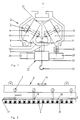
- 1 and 2 show a hollow profile rail, denoted overall by 1, of a suspension track 3 movable on pairs of rollers 2, with two on the underside of the interior 4 of the hollow rail 1 separated by a longitudinal slot 7 serving as a passage of a supporting body 5 of a load 6 to be conveyed, apart from cornering - flat carriageways 8 and 9 for one roller 10, 11 of each pair of rollers 2 of the suspension track 3.
- the rollers 10, 11 of each pair of rollers 2 are connected to one another by a bracket 12 receiving the support body 5.
- the bracket 12 contains bearings 13 for the axes 14, 15 of the pair of rollers 2.
- the axes 14, 15 are inclined towards each other in the direction of the longitudinal slot 7 downwards.
- the two carriageways 8, 9 have the same inclination transverse to their longitudinal direction or to the longitudinal direction 16 of the hollow profile rail 1.
- the inclination of the carriageways 8, 9 can be of the order of magnitude between 30 and 60 °, preferably around 45 °.
- the inclination depends on the width B of the longitudinal slot and is chosen so that dirt falling on the roadways 8.9 in the sense of a Self-cleaning of the interior 4 can trickle down automatically by the moving rollers 10, 11.
- the width B of the longitudinal slot 7 is made as large as possible, in particular large, against the width of the carriageway 8, 9.
- the inner surface of the rail 1 is formed at the top as a counter pressure surface 21 for the rollers 10, 11.
- the surface 21 prevents the rollers 10, 11 from falling out of the roadway 8, 9; in normal straight travel, the pair of rollers 2 does not abut the counter pressure surface 21.
- the support chain consists of a plurality of support carriages 18 which are connected to one another by articulated couplings 19.
- Each carrier car 18 has at least one support coupling 20 for suspending a load 21.
- three support couplings 20 are provided on each support car 18; in each case one support coupling 20 is located in the area of the articulated coupling 19, the other two support couplings 20 are located between two articulated couplings 19 in each case.
- the embodiment shown in FIG. 2 is particularly suitable for the transport of cross-wound bobbins in the textile industry.
- friction wheel drive This consists of a friction wheel 23 driven by a motor 22 with a counter wheel 24.
- Such friction wheel drives are provided at certain intervals along the length of the rail 1. Since friction wheel drives require relatively smooth drive surfaces 25 on the support chain 17, such drives are only provided at certain intervals on straight parts of the rail 1.
Landscapes
- Engineering & Computer Science (AREA)
- Mechanical Engineering (AREA)
- Architecture (AREA)
- Civil Engineering (AREA)
- Structural Engineering (AREA)
- Chain Conveyers (AREA)
Abstract
Claims (1)
- Voie suspendue (3) à rail creux profilé autoporteur (1) incluant deux voies de roulement (8, 9) planes en soi - abstraction faite des courbes - séparées sur le côté inférieur de l'espace intérieur (4) du rail creux (1) par une fente longitudinale (7) servant au passage d'un corps porteur (5) d'une charge (6) à transporter, et destinée chacune à un galet de roulement (10, 11) d'une paire (2) de galets de roulement de la voie suspendue (3), les galets de roulement (10, 11) de chaque paire (2) de galets de roulement étant reliés entre eux par un étrier (12) qui reçoit le corps porteur (5), les axes (14, 15) des galets de roulement (10, 11) de chaque paire (2) de galets de roulement étant inclinés vers le bas l'un vers l'autre en direction de la fente longitudinale (7) et les deux voies de roulement (8, 9) étant inclinées vers le bas, du même angle que les axes (14, 15) des galets de roulement, en direction de la fente longitudinale (7) transversalement à leur direction longitudinale (16),
caractérisée en ce que
l'espace intérieur (4) possède, sur le côté supérieur opposé aux voies de roulement (8, 9), des surfaces (21) de contre-appui agissant en tant que bloqueur et glissière de guidage des galets (10, 11) et en ce que la voie suspendue (3) possède un entraînement, en particulier un entraînement par friction (22, 23, 24) , agissant au-dessous de la paire (2) de galets sur le corps porteur (5) ou sur une chaîne porteuse (17) qui s'y trouve.
Applications Claiming Priority (3)
| Application Number | Priority Date | Filing Date | Title |
|---|---|---|---|
| DE3941459 | 1989-12-15 | ||
| DE3941459A DE3941459A1 (de) | 1989-12-15 | 1989-12-15 | Selbsttragende profilhohlschiene |
| PCT/DE1990/000947 WO1991008970A1 (fr) | 1989-12-15 | 1990-12-08 | Rail creux profile autoporteur |
Publications (2)
| Publication Number | Publication Date |
|---|---|
| EP0458921A1 EP0458921A1 (fr) | 1991-12-04 |
| EP0458921B1 true EP0458921B1 (fr) | 1995-02-15 |
Family
ID=6395540
Family Applications (1)
| Application Number | Title | Priority Date | Filing Date |
|---|---|---|---|
| EP90917705A Expired - Lifetime EP0458921B1 (fr) | 1989-12-15 | 1990-12-08 | Conveyor avec rail creux profile autoporteur |
Country Status (3)
| Country | Link |
|---|---|
| EP (1) | EP0458921B1 (fr) |
| DE (2) | DE3941459A1 (fr) |
| WO (1) | WO1991008970A1 (fr) |
Cited By (1)
| Publication number | Priority date | Publication date | Assignee | Title |
|---|---|---|---|---|
| EP2130971A2 (fr) | 2008-06-03 | 2009-12-09 | Wilhelm Strödter | Un support multifonctionnel |
Families Citing this family (8)
| Publication number | Priority date | Publication date | Assignee | Title |
|---|---|---|---|---|
| DE4112767A1 (de) * | 1991-04-19 | 1992-10-29 | Gregor Gebald | Weiche einer profilhohlschiene |
| DE4222195A1 (de) * | 1992-07-07 | 1994-01-13 | Innovatex Materials Handling G | Weiche einer Profilhohlschiene |
| DE4323127A1 (de) * | 1993-02-15 | 1994-08-18 | E & Pk Ingbuero | Kurvenbandförderer mit gurtbandrollenfreiem Traggerüst |
| US5443151A (en) * | 1994-03-30 | 1995-08-22 | Gorbel, Inc. | Conveyor or crane beam of extruded aluminum alloy |
| SE506609C2 (sv) * | 1996-05-31 | 1998-01-19 | Ocs Overhead Conveyor Sys Ab | Hängtransportöranordning |
| SE511610C2 (sv) * | 1997-12-16 | 1999-10-25 | Bygg & Industriservice E Jacob | Anordning för förflyttning av föremål |
| DE202008007100U1 (de) * | 2008-05-27 | 2009-10-08 | Psb Intralogistics Gmbh | Hängeförderanlage |
| DE102018219583C5 (de) * | 2018-11-15 | 2025-09-11 | Dürkopp Fördertechnik GmbH | Förderanlage und Verfahren zum Fördern von Waren |
Family Cites Families (4)
| Publication number | Priority date | Publication date | Assignee | Title |
|---|---|---|---|---|
| GB463392A (en) * | 1935-11-21 | 1937-03-30 | Paul Gerhard Roemer | Improvements in chain conveyors |
| FR1171401A (fr) * | 1957-01-15 | 1959-01-26 | Chainveyor Corp | Transporteur à monorail tubulaire |
| US3855937A (en) * | 1974-03-14 | 1974-12-24 | K Caudill | Electrified trolley track |
| DE3812852A1 (de) * | 1988-04-18 | 1989-11-02 | Franz Gaertner | Handhaengebahn fuer die innerbetriebliche haengefoerderung in der bekleidungsindustrie |
-
1989
- 1989-12-15 DE DE3941459A patent/DE3941459A1/de not_active Withdrawn
-
1990
- 1990-12-08 DE DE59008486T patent/DE59008486D1/de not_active Expired - Fee Related
- 1990-12-08 WO PCT/DE1990/000947 patent/WO1991008970A1/fr not_active Ceased
- 1990-12-08 EP EP90917705A patent/EP0458921B1/fr not_active Expired - Lifetime
Cited By (2)
| Publication number | Priority date | Publication date | Assignee | Title |
|---|---|---|---|---|
| EP2130971A2 (fr) | 2008-06-03 | 2009-12-09 | Wilhelm Strödter | Un support multifonctionnel |
| DE102008026442A1 (de) | 2008-06-03 | 2009-12-10 | Strödter, Wilhelm | Multifunktionsträger |
Also Published As
| Publication number | Publication date |
|---|---|
| DE59008486D1 (de) | 1995-03-23 |
| EP0458921A1 (fr) | 1991-12-04 |
| DE3941459A1 (de) | 1991-06-20 |
| WO1991008970A1 (fr) | 1991-06-27 |
Similar Documents
| Publication | Publication Date | Title |
|---|---|---|
| EP1071622B1 (fr) | Support de produits a transporter | |
| CH662164A5 (de) | Vorrichtung zum fuehren von flexiblen versorgungsleitungen. | |
| EP0458921B1 (fr) | Conveyor avec rail creux profile autoporteur | |
| DE1276679C2 (de) | Haengebahn-Anlage | |
| CH680921A5 (fr) | ||
| DE3047055A1 (de) | Transporteinrichtung | |
| DE1202717B (de) | Bandfoerderer | |
| EP0297331A1 (fr) | Disposition de rail de guidage d'un système de convoyeur aérien | |
| DE3336190C2 (de) | Stauketten-Fördereinrichtung für hängende Stückgüter | |
| DE2839330C2 (de) | Vorrichtung zur Änderung der Fahrtrichtung eines zu transportierenden Gegenstandes | |
| WO2016008552A1 (fr) | Véhicule d'entraînement destiné à un dispositif de transport et système de transport | |
| DE202012013157U1 (de) | Hängefördereinrichtung | |
| DE3707395C1 (en) | Return system for rail-bound transport trucks without self-propulsion | |
| DE3929301A1 (de) | Schienenhaengebahn, insbesondere fuer den innerbetrieblichen materialtransport | |
| DE969050C (de) | Endlose Foerderer, insbesondere fuer den Grubenbetrieb | |
| EP2466006B1 (fr) | Dispositif de transfert pour chariots de transport et installation de transport en étant équipée | |
| EP1190965B1 (fr) | Porte-charges pour le transport d'articles dans un système de convoyeur aérien | |
| EP0644095A1 (fr) | Pince pouvant être accouplée à un câble | |
| DE1430959C (de) | Vorrichtung zum allseitigen Fuhren eines eine Bahn betreibenden Zugseils | |
| DE2949090A1 (de) | Foerderanlage | |
| DE2802401A1 (de) | Haengebahnanlage | |
| DE4222195A1 (de) | Weiche einer Profilhohlschiene | |
| DE2910780A1 (de) | Gehaengeuebergabevorrichtung fuer haengekettenfoerderer | |
| DE1183019B (de) | Durchlauflagergestell fuer zickzackartig abwaerts bewegte, rollbare Gegenstaende, insbesondere Faesser | |
| DE3049571A1 (de) | Hubeinrichtung fuer mit einer haengebahn des untertaegigen bergbaus zu transportierende schwerlasten |
Legal Events
| Date | Code | Title | Description |
|---|---|---|---|
| PUAI | Public reference made under article 153(3) epc to a published international application that has entered the european phase |
Free format text: ORIGINAL CODE: 0009012 |
|
| AK | Designated contracting states |
Kind code of ref document: A1 Designated state(s): BE CH DE FR IT LI |
|
| 17P | Request for examination filed |
Effective date: 19911116 |
|
| 17Q | First examination report despatched |
Effective date: 19930608 |
|
| ITF | It: translation for a ep patent filed | ||
| GRAA | (expected) grant |
Free format text: ORIGINAL CODE: 0009210 |
|
| AK | Designated contracting states |
Kind code of ref document: B1 Designated state(s): BE CH DE FR IT LI |
|
| REF | Corresponds to: |
Ref document number: 59008486 Country of ref document: DE Date of ref document: 19950323 |
|
| ET | Fr: translation filed | ||
| PLBE | No opposition filed within time limit |
Free format text: ORIGINAL CODE: 0009261 |
|
| STAA | Information on the status of an ep patent application or granted ep patent |
Free format text: STATUS: NO OPPOSITION FILED WITHIN TIME LIMIT |
|
| 26N | No opposition filed | ||
| PGFP | Annual fee paid to national office [announced via postgrant information from national office to epo] |
Ref country code: FR Payment date: 19960515 Year of fee payment: 6 |
|
| PGFP | Annual fee paid to national office [announced via postgrant information from national office to epo] |
Ref country code: DE Payment date: 19960520 Year of fee payment: 6 Ref country code: CH Payment date: 19960520 Year of fee payment: 6 |
|
| PGFP | Annual fee paid to national office [announced via postgrant information from national office to epo] |
Ref country code: BE Payment date: 19960521 Year of fee payment: 6 |
|
| PG25 | Lapsed in a contracting state [announced via postgrant information from national office to epo] |
Ref country code: LI Effective date: 19961231 Ref country code: CH Effective date: 19961231 Ref country code: BE Effective date: 19961231 |
|
| BERE | Be: lapsed |
Owner name: TRANSTEX PRODUKTIONSGESELLSCHAFT M.B.H. Effective date: 19961231 |
|
| REG | Reference to a national code |
Ref country code: CH Ref legal event code: PL |
|
| PG25 | Lapsed in a contracting state [announced via postgrant information from national office to epo] |
Ref country code: FR Effective date: 19970829 |
|
| PG25 | Lapsed in a contracting state [announced via postgrant information from national office to epo] |
Ref country code: DE Effective date: 19970902 |
|
| REG | Reference to a national code |
Ref country code: FR Ref legal event code: ST |
|
| PG25 | Lapsed in a contracting state [announced via postgrant information from national office to epo] |
Ref country code: IT Free format text: LAPSE BECAUSE OF NON-PAYMENT OF DUE FEES Effective date: 20051208 |