EP0458921B1 - Hängebahn mit selbsttragender profilhohlschiene - Google Patents
Hängebahn mit selbsttragender profilhohlschiene Download PDFInfo
- Publication number
- EP0458921B1 EP0458921B1 EP90917705A EP90917705A EP0458921B1 EP 0458921 B1 EP0458921 B1 EP 0458921B1 EP 90917705 A EP90917705 A EP 90917705A EP 90917705 A EP90917705 A EP 90917705A EP 0458921 B1 EP0458921 B1 EP 0458921B1
- Authority
- EP
- European Patent Office
- Prior art keywords
- rollers
- pair
- wheels
- carriageways
- rail
- Prior art date
- Legal status (The legal status is an assumption and is not a legal conclusion. Google has not performed a legal analysis and makes no representation as to the accuracy of the status listed.)
- Expired - Lifetime
Links
- 230000004888 barrier function Effects 0.000 claims description 2
- 238000004140 cleaning Methods 0.000 abstract description 7
- 239000004753 textile Substances 0.000 abstract description 7
- 230000008878 coupling Effects 0.000 description 9
- 238000010168 coupling process Methods 0.000 description 9
- 238000005859 coupling reaction Methods 0.000 description 9
- 239000000428 dust Substances 0.000 description 7
- 239000000725 suspension Substances 0.000 description 4
- 230000015572 biosynthetic process Effects 0.000 description 1
- 239000003795 chemical substances by application Substances 0.000 description 1
- 230000006835 compression Effects 0.000 description 1
- 238000007906 compression Methods 0.000 description 1
- 239000002245 particle Substances 0.000 description 1
- 230000000149 penetrating effect Effects 0.000 description 1
- 238000009987 spinning Methods 0.000 description 1
- 238000004804 winding Methods 0.000 description 1
Images
Classifications
-
- E—FIXED CONSTRUCTIONS
- E01—CONSTRUCTION OF ROADS, RAILWAYS, OR BRIDGES
- E01B—PERMANENT WAY; PERMANENT-WAY TOOLS; MACHINES FOR MAKING RAILWAYS OF ALL KINDS
- E01B25/00—Tracks for special kinds of railways
- E01B25/22—Tracks for railways with the vehicle suspended from rigid supporting rails
- E01B25/24—Supporting rails; Auxiliary balancing rails; Supports or connections for rails
-
- B—PERFORMING OPERATIONS; TRANSPORTING
- B65—CONVEYING; PACKING; STORING; HANDLING THIN OR FILAMENTARY MATERIAL
- B65G—TRANSPORT OR STORAGE DEVICES, e.g. CONVEYORS FOR LOADING OR TIPPING, SHOP CONVEYOR SYSTEMS OR PNEUMATIC TUBE CONVEYORS
- B65G17/00—Conveyors having an endless traction element, e.g. a chain, transmitting movement to a continuous or substantially-continuous load-carrying surface or to a series of individual load-carriers; Endless-chain conveyors in which the chains form the load-carrying surface
- B65G17/20—Conveyors having an endless traction element, e.g. a chain, transmitting movement to a continuous or substantially-continuous load-carrying surface or to a series of individual load-carriers; Endless-chain conveyors in which the chains form the load-carrying surface comprising load-carriers suspended from overhead traction chains
-
- B—PERFORMING OPERATIONS; TRANSPORTING
- B65—CONVEYING; PACKING; STORING; HANDLING THIN OR FILAMENTARY MATERIAL
- B65G—TRANSPORT OR STORAGE DEVICES, e.g. CONVEYORS FOR LOADING OR TIPPING, SHOP CONVEYOR SYSTEMS OR PNEUMATIC TUBE CONVEYORS
- B65G19/00—Conveyors comprising an impeller or a series of impellers carried by an endless traction element and arranged to move articles or materials over a supporting surface or underlying material, e.g. endless scraper conveyors
- B65G19/02—Conveyors comprising an impeller or a series of impellers carried by an endless traction element and arranged to move articles or materials over a supporting surface or underlying material, e.g. endless scraper conveyors for articles, e.g. for containers
- B65G19/025—Conveyors comprising an impeller or a series of impellers carried by an endless traction element and arranged to move articles or materials over a supporting surface or underlying material, e.g. endless scraper conveyors for articles, e.g. for containers for suspended articles
-
- B—PERFORMING OPERATIONS; TRANSPORTING
- B65—CONVEYING; PACKING; STORING; HANDLING THIN OR FILAMENTARY MATERIAL
- B65G—TRANSPORT OR STORAGE DEVICES, e.g. CONVEYORS FOR LOADING OR TIPPING, SHOP CONVEYOR SYSTEMS OR PNEUMATIC TUBE CONVEYORS
- B65G21/00—Supporting or protective framework or housings for endless load-carriers or traction elements of belt or chain conveyors
- B65G21/20—Means incorporated in, or attached to, framework or housings for guiding load-carriers, traction elements or loads supported on moving surfaces
- B65G21/22—Rails or the like engaging sliding elements or rollers attached to load-carriers or traction elements
-
- B—PERFORMING OPERATIONS; TRANSPORTING
- B65—CONVEYING; PACKING; STORING; HANDLING THIN OR FILAMENTARY MATERIAL
- B65G—TRANSPORT OR STORAGE DEVICES, e.g. CONVEYORS FOR LOADING OR TIPPING, SHOP CONVEYOR SYSTEMS OR PNEUMATIC TUBE CONVEYORS
- B65G2201/00—Indexing codes relating to handling devices, e.g. conveyors, characterised by the type of product or load being conveyed or handled
- B65G2201/02—Articles
Definitions
- the invention relates to a monorail with self-supporting hollow profile rail with two on the underside of the interior of the hollow rail separated by a longitudinal slot serving as a passage of a supporting body of a load to be conveyed, in itself - apart from curves - flat lanes for one roller of a pair of rollers of the monorail, whereby the rollers of each pair of rollers are connected to one another by a bracket receiving the support body, the axes of the rollers of each pair of rollers are inclined downwards towards one another in the direction of the longitudinal slot and the two tracks are inclined transversely to their longitudinal direction by the same angle as the roller axes are inclined downwards towards the longitudinal slot are.
- a running rail for overhead conveyors in particular for parts transport in the textile industry, which has in cross-section two roof-shaped mutually facing, each having a roller track on the upper side for a pair of rollers carrying legs.
- the rollers of the pair of rollers have axially inclined axes and are held together with the help of a bracket.
- a load can be attached to the bracket.
- a similar overhead conveyor system is given in DD-A-260 266. This publication primarily relates to the formation of a switch in the course of the running rail.
- EP-A-0 297 331 proposes a running rail spanned out of two parallel to the running direction of the running rollers, each with one running surface for the wheels, except for one Provide longitudinal slot for a downward-facing transport goods carrier essentially closed housing.
- the two driving surfaces within the housing are inclined away from each other transversely to the direction of travel.
- the housing receiving the rollers is sealed relatively well, but inevitably penetrating lint dust remains in the housing and collects there.
- the accumulating dirt builds up on or next to the road surface, so that the wheels are pushed upwards from the road surface and eventually jam inside the housing. Since the dust is often mixed with finishing agents or the like in textile factories, the dust and lint particles gradually stick to one another, so that cleaning generally requires unscrewing the hollow profile rail.
- a further disadvantage of the running track arrangement known from EP-A-0 297 331 is that the drive provided there presses from above onto the supporting body connecting the running rolls and thereby further increases the contact pressure of the running rolls on the running surfaces. This contact pressure leads to an increased compression of lint parts clinging to the running surfaces and thus to a further complication of each cleaning.
- EP-A-0 338 500 (FIG. 2) describes a hollow profile rail which is externally similar to that of the type mentioned at the outset, but only serves as a hanging conveyor system in the clothing industry, that is to say for hanging clothes hangers.
- the casters are covered against dust or lint and the track rollers or their rails are such that dirt can be removed by self-cleaning while driving, despite covering the track rollers or rails, the storage of the track rollers in the But rails is so unstable that a rocking back and forth of the respectively suspended web about its longitudinal axis, that is, an alternate lifting of the rollers on the right and left side is inevitable.
- Such instability may be acceptable in the clothing industry if a clothes rail is attached to the overhead conveyor, on which clothes hang, for example on hangers, in such a way that a possible rocking movement of the monorail about its longitudinal axis is only passed on to the attached clothes in a dampened manner. because they can counter-move the clothes rail.
- bobbins in the textile industry e.g. from the flyer, from the spinning machine or from the winding machine in an automatic transport system.
- Such a transport system should be able to automatically take the bobbin at a bobbin delivery point and automatically let it go at a bobbin removal point.
- Corresponding grippers generally have rotary suspensions which are to be introduced axially into the sleeve of the respective coil and which allow an almost free rotation about the sleeve axis and at the same time oscillate in one direction around a point.
- Such rotary suspensions can come loose if jerky impacts, such as those caused by a rocking movement of the overhead conveyor track, act.
- the invention has for its object to substantially exclude rocking movements of the respective overhead conveyor track running the hollow profile rails.
- the solution according to the invention for the hollow profile rail mentioned at the outset is that its interior on the upper side opposite the carriageways has counter pressure surfaces as a lock against slipping out of the rollers and as a guide for the rollers, and that the overhead conveyor has one below the pair of rollers on the support body or on a support chain located thereon attacking drive, in particular friction wheel drive.
- the roles are stored in the interior of the hollow profile so that they have a certain mobility have perpendicular to the axis up, but that the pair of rollers can not slide up out of the position on the road.
- the inner surfaces opposite the carriageways are formed on the top of the hollow profile as counter pressure surfaces of the rollers. These counter pressure surfaces are normally not touched by the rollers, but they act as a barrier against the pair of rollers falling out from its position on the two lanes.
- the drive advancing the pair of rollers in the transport direction is attached to the support body hanging on the pair of rollers or to parts attached to it, e.g. B. attacks a chain so that the weight acting on the pair of rollers is not significantly increased.
- the attack should preferably take place in such a way that not only does no increase in weight but rather a decrease in weight occur.
- a drive which acts directly on the train preferably as a friction wheel drive, is provided.
- the number of pairs of rollers required to carry a trolley train depends on the size of the load to be carried. If, for example, bobbins, in particular cross-wound bobbins or flyer bobbins, are to be carried in the textile industry, the weight of three cross-wound bobbins or the like can be taken up by each pair of rollers according to the invention, because the pair of rollers practically only the weight of the wagons and bobbins attached, but not an additional load must take up by a drive.
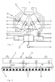
- 1 and 2 show a hollow profile rail, denoted overall by 1, of a suspension track 3 movable on pairs of rollers 2, with two on the underside of the interior 4 of the hollow rail 1 separated by a longitudinal slot 7 serving as a passage of a supporting body 5 of a load 6 to be conveyed, apart from cornering - flat carriageways 8 and 9 for one roller 10, 11 of each pair of rollers 2 of the suspension track 3.
- the rollers 10, 11 of each pair of rollers 2 are connected to one another by a bracket 12 receiving the support body 5.
- the bracket 12 contains bearings 13 for the axes 14, 15 of the pair of rollers 2.
- the axes 14, 15 are inclined towards each other in the direction of the longitudinal slot 7 downwards.
- the two carriageways 8, 9 have the same inclination transverse to their longitudinal direction or to the longitudinal direction 16 of the hollow profile rail 1.
- the inclination of the carriageways 8, 9 can be of the order of magnitude between 30 and 60 °, preferably around 45 °.
- the inclination depends on the width B of the longitudinal slot and is chosen so that dirt falling on the roadways 8.9 in the sense of a Self-cleaning of the interior 4 can trickle down automatically by the moving rollers 10, 11.
- the width B of the longitudinal slot 7 is made as large as possible, in particular large, against the width of the carriageway 8, 9.
- the inner surface of the rail 1 is formed at the top as a counter pressure surface 21 for the rollers 10, 11.
- the surface 21 prevents the rollers 10, 11 from falling out of the roadway 8, 9; in normal straight travel, the pair of rollers 2 does not abut the counter pressure surface 21.
- the support chain consists of a plurality of support carriages 18 which are connected to one another by articulated couplings 19.
- Each carrier car 18 has at least one support coupling 20 for suspending a load 21.
- three support couplings 20 are provided on each support car 18; in each case one support coupling 20 is located in the area of the articulated coupling 19, the other two support couplings 20 are located between two articulated couplings 19 in each case.
- the embodiment shown in FIG. 2 is particularly suitable for the transport of cross-wound bobbins in the textile industry.
- friction wheel drive This consists of a friction wheel 23 driven by a motor 22 with a counter wheel 24.
- Such friction wheel drives are provided at certain intervals along the length of the rail 1. Since friction wheel drives require relatively smooth drive surfaces 25 on the support chain 17, such drives are only provided at certain intervals on straight parts of the rail 1.
Landscapes
- Engineering & Computer Science (AREA)
- Mechanical Engineering (AREA)
- Architecture (AREA)
- Civil Engineering (AREA)
- Structural Engineering (AREA)
- Chain Conveyers (AREA)
Abstract
Description
- Die Erfindung betrifft eine Hängebahn mit selbsttragender Profilhohlschiene mit zwei auf der Unterseite des Innenraums der Hohlschiene durch einen als Durchlaß eines Tragkörpers einer zu fördernden Last dienenden Längsschlitz getrennten, an sich - abgesehen von Kurven - ebenen Fahrbahnen für je eine Laufrolle eines Laufrollenpaars der Hängebahn, wobei die Laufrollen jedes Laufrollenpaars untereinander durch einen den Tragkörper aufnehmenden Bügel verbunden sind, die Achsen der Laufrollen jedes Laufrollenpaars gegeneinander in Richtung auf den Längsschlitz nach unten geneigt sind und die beiden Fahrbahnen quer zu ihrer Langsrichtung um denselben Winkel Wie die Laufrollenachsen zum Langsschlitz hin nach unten geneigt sind.
- Aus der DE-A- 35 35 758 ist eine Laufschiene für Hängeförderbahnen, insbesondere zum Teiletransport in der Textilindustrie, bekannt, die im Querschnitt zwei dachförmig zueinanderweisende, oberseitig je eine Rollenlaufbahn für ein Laufrollenpaar tragende Schenkel aufweist. Die Laufrollen des Laufrollenpaars besitzen schräg zueinander stehende Achsen und werden mit Hilfe eines Bügels zusammengehalten. An dem Bügel kann eine Last befestigt werden. Ein ähnliches Hängefördersystem wird in der DD-A- 260 266 angegeben. Diese Druckschrift bezieht sich in erster Linie auf die Ausbildung einer Weiche im Zuge der Laufschiene.
- In der Textilindustrie haben sich die vorgenannten Hängefördersysteme mit allseitig offenen Laufrollen nicht bewährt, weil der dort unvermeidliche Flusenstaub früher oder später zu einer Verstopfung der sich drehenden und bewegenden Teile führt, wenn die Schienen und die Laufrollen nicht ständig gereinigt werden. Aus diesem Grunde ist eine selbsttragende Profilhohlschiene entwickelt worden, die die eigentlichen Laufschienenflächen, die Rollen und gegebenenfalls den an den Rollen hängenden Trolleyzug gegen den Flug- bzw. Flusenstaub abkapseln soll.
- Um die Laufeigenschaften eines Hängefördersystems zu stabilisieren und zugleich die Profilhohlschiene gegen Staub möglichst gut abzudichten, wird in der EP-A-0 297 331 vorgeschlagen, ein aus zwei in Fahrtrichtung der Laufrollen parallelen Laufschienen mit je einer Fahrfläche für die Räder aufgespanntes, bis auf einen Längsschlitz für eine nach unten gerichteten Transportgutträger im wesentlichen geschlossenes Gehäuse vorzusehen. Die beiden Fahrflächen innerhalb des Gehäuses werden dabei quer zur Fahrtrichtung voneinander weggeneigt. Dadurch wird das die Laufrollen aufnehmende Gehäuse zwar relativ gut abgedichtet, unvermeidlich doch eindringender Flusen-Staub bleibt aber im Gehäuse und sammelt sich dort. Der sich ansammelnde Schmutz staut sich auf oder neben der Fahrbahnfläche, so daß die Räder von der Fahrbahnfläche nach oben gedrückt werden und schließlich im Innern des Gehäuses klemmen. Da der Staub in Textilfabriken häufig mit Avivagen oder dergleichen versetzt ist, kleben die Staub- und Flusen-Partikel allmählich aneinander, so daß eine Reinigung im allgemeinen ein Auseinanderschrauben der Hohlprofilschiene erfordert.
- Ein weiterer Nachteil der aus der EP-A-0 297 331 bekannten Laufschienenanordnung besteht darin, daß der dort vorgesehene Antrieb von oben auf den die Laufrollen verbindenden Tragkörper drückt und dadurch die Anpreßkraft der Laufrollen auf die Laufflächen noch erhöht. Diese Anpreßkraft führt zu einer erhöhten Verdichtung von sich auf den Laufflächen anklammernden Flusenteilen und damit zu einer weiteren Erschwernis jeder Reinigung.
- Eine Profilhohlschiene, die derjenigen eingangs genannter Art äußerlich ähnlich ist, aber lediglich als Hängefördersystem in der Bekleidungsindustrie, also zum Aufhängen von Kleiderbügeln, dient, wird in der EP-A-0 338 500 (Fig. 2) beschrieben. In der bekannten Laufschienenanordnung werden die Laufrollen zwar gegenüber Flugstaub bzw. Flusenbefall abgedeckt und die Laufrollen bzw. deren Schienen stehen so, daß etwa trotz Abdeckung an die Laufrollen bzw. Schienen gelangter Schmutz durch Selbstreinigung beim Fahren abgetragen werden kann, die Lagerung der Laufrollen in den Schienen ist aber so instabil, daß ein Hin und Herschaukeln der jeweils eingehängten Bahn um deren Längsachse, also ein wechselweises Abheben der Laufrollen auf der rechten und linken Seite unvermeidlich ist. Eine solche Instabilität mag in der Bekleidungsindustrie hinzunehmen sein, wenn an der Hängeförderbahn eine Kleiderstange befestigt ist, auf der wiederum, z.B. auf Bügeln, Kleidungsstücke hängen, derart, daß eine eventuelle Schaukelbewegung der Hängebahn um deren Längsachse nur gedämpft auf die anhängenden Kleidungsstücke weitergegeben wird, weil diese eine Gegenbewegung um die Kleiderstange ausführen können. Anders ist die Situation, wenn in der Textilindustrie Spulen, z.B. vom Flyer, von der Spinnmaschine oder von der Spulmaschine in einem automatischen Transportsystem einzeln angehängt werden. Ein solches Transportsystem soll in der Lage sein, die Spule an einer Spulenlieferstelle automatisch zu fassen und an einer Spulenabnahmestelle automatisch loszulassen. Entsprechende Greifer besitzen im allgemeinen Drehaufhängungen, die axial in die Hülse der jeweiligen Spule einzuführen sind und eine nahezu freie Rotation um die Hülsenachse und zugleich ein Pendeln in jeder Richtung um einen Punkt erlaubt. Derartige Drehaufhängungen können sich lösen, wenn ruckartige Stöße, wie sie durch eine Schaukelbewegung der Hängeförderbahn verursacht werden, einwirken.
- Der Erfindung liegt die Aufgabe zugrunde, Schaukelbewegungen der jeweiligen der Profilhohlschienen laufenden Hängeförderbahn im wesentlichen auszuschließen. Die erfindungsgemäße Lösung besteht für die eingangs genannte profilhohlschiene darin, daß deren Innenraum an der den Fahrbahnen gegenüberliegenden Oberseite Gegendruckflächen als Sperre gegen ein Herausrutschen der Rollen und als Führung der Rollen besitzt und daß die Hängebahn eine unterhalb des Rollenpaars am Tragkörper oder an einer daran befindlichen Tragkette angreifenden Antrieb, insbesondere Reibradantrieb, besitzt.
- Erfindungsgemäß werden also die Rollen im Innenraum des Hohlprofils so gelagert, daß sie zwar eine gewisse Beweglichkeit senkrecht zur Achse nach oben besitzen, daß aber das Rollenpaar nicht nach oben aus der Position auf den Fahrbahnen herausrutschen kann. Dazu werden die den Fahrbahnen gegenüberliegenden Innenflächen auf der Oberseite des Hohlprofils als Gegendruckflächen der Rollen ausgebildet. Diese Gegendruckflächen werden normalerweise von den Rollen nicht berührt, sie wirken jedoch als Sperre gegen ein Herausfallen des Rollenpaars aus seiner Position auf den beiden Fahrbahnen.
- Für die Selbstreinigung und Reinhaltung des Innenraums des Hohlprofils ist es auch wichtig, daß die Andruckkraft der Rollen auf den zugehörigen Laufflächen möglichst gering gehalten wird, um ein Verdichten und Ankleben von eventuell dort liegendem Schmutz zu vermeiden. In diesem Sinne ist es erfindungsgemäß vorteilhaft, wenn der das Rollenpaar in Transportrichtung vorschiebende Antrieb an den an dem Rollenpaar hängenden Tragkörper bzw. an daran befestigte Teile, z. B. eine Kette, so angreift, daß das auf das Rollenpaar wirkende Gewicht nicht nennenswert vergrößert wird. Vorzugsweise soll der Angriff so erfolgen, daß nicht nur keine Gewichtsvergrößerung sondern eher Gewichtsverminderung auftritt. Um das zu erreichen, wird bei Zusammenfassung mehrerer Rollenpaare als Tragelemente eines Trolleyzugs ein unmittelbar auf den Zug wirkender Antrieb, vorzugsweise als Reibradantrieb, vorgesehen.
- Die Zahl der Rollenpaare, die zum Tragen eines Trolleyzugs erforderlich sind, hängt von der Größe der aufzunehmenden Last ab. Wenn beispielsweise in der Textilindustrie Spulen, insbesondere Kreuzspulen oder Flyerspulen, zu tragen sind, kann erfindungsgemäß von jedem Rollenpaar das Gewicht von drei Kreuzspulen oder dergleichen aufgenommen werden, weil das Rollenpaar praktisch nur das Gewicht der daran hängenden Wagen und Spulen, nicht jedoch eine zusätzliche Belastung durch einen Antrieb aufnehmen muß.
- Anhand der schematischen Darstellung in der beiliegenden Zeichnung werden Einzelheiten der Erfindung erläutert. Es zeigen:
- Fig. 1
- einen Schnitt quer zur Längsrichtung einer Profilhohlschiene mit darin gelagertem Rollenpaar; und
- Fig. 2
- eine Seitenansicht einer Profilhohlschiene mit daran hängendem Trolleyzug, teilweise im Schnitt.
- Fig. 1 und 2 zeigen eine insgesamt mit 1 bezeichnete Profilhohlschiene einer auf Laufrollenpaaren 2 verfahrbaren Hängebahn 3 mit zwei auf der Unterseite des Innenraums 4 der Hohlschiene 1 durch einen als Durchlaß eines Tragkörpers 5 einer zu fördernden Last 6 dienenden Längsschlitzes 7 getrennte, in sich - abgesehen vom Kurven - ebenen Fahrbahnen 8 und 9 für je eine Laufrolle 10, 11 jedes Laufrollenpaars 2 der Hängebahn 3.
- Erfindungsgemäß werden die Laufrollen 10, 11 jedes Laufrollenpaars 2 untereinander durch einen den Tragkörper 5 aufnehmenden Bügel 12 verbunden. Der Bügel 12 enthält Lager 13 für die Achsen 14, 15 des Laufrollenpaars 2. Die Achsen 14, 15 werden gegeneinander in Richtung auf den Längsschlitz 7 nach unten geneigt. Dieselbe Neigung besitzen die beiden Fahrbahnen 8, 9 quer zu ihrer Längsrichtung bzw. zur Längsrichtung 16 der Profilhohlschiene 1. Die Neigung der Fahrbahnen 8, 9 kann größenordnungsmäßig zwischen 30 und 60° , vorzugsweise bei etwa 45°, liegen. Die Neigung hängt ab von der Breite B des Längsschlitzes und wird so gewählt, daß etwa auf die Fahrbahnen 8,9 fallender Schmutz im Sinne einer Selbstreinigung des Innenraums 4 durch die fahrenden Rollen 10, 11 selbsttätig herabrieseln kann. Um eine möglichst vollständige Reinigung zu erreichen und um ein Festkleben von Schmutz auf den Fahrbahnen 8, 9 im wesentlichen auszuschließen, wird die Breite B des Längsschlitzes 7 möglichst groß, insbesondere groß gegen die Breite der Fahrbahn 8, 9 gebracht. Die Innenfläche der Schiene 1 wird oben als Gegendruckfläche 21 für die Rollen 10, 11 ausgebildet. Die Fläche 21 verhindert ein Herausfallen der Rollen 10, 11 aus der Fahrbahn 8, 9; bei mormaler gerader Fahrt stößt das Rollenpaar 2 nicht an die Gegendruckfläche 21 an.
- An dem die Achsen 14, 15 der Laufrollen 10, 11 lagernden und verbindenden Bügel 12 wird ein Tragkörper 5 und an diesen eine Tragkette 17 befestigt. Die Tragkette besteht aus mehreren Tragwagen 18, die durch Gelenkkupplungen 19 miteinander verbunden werden. Jeder Tragwagen 18 besitzt mindestens eine Tragkupplung 20 zum Aufhängen einer Last 21. Im Ausführungsbeispiel werden an jedem Tragwagen 18 im Durchschnitt drei Tragkupplungen 20 vorgesehen; jeweils eine Tragkupplung 20 befindet sich im Bereich der Gelenkkupplung 19, die beiden anderen Tragkupplungen 20 befinden sich zwischen je zwei Gelenkkupplungen 19. Die in Fig. 2 dargestellte Ausführung eignet sich besonders zum Transport von Kreuzspulen in der Textilindustrie.
- Der Trolleyzug nach Fig. 1 und 2 besitzt einen Reibradantrieb. Dieser besteht aus einem über einen Motor 22 getriebenen Reibrad 23 mit Gegenrad 24. Auf der Länge der Schiene 1 werden in gewissen Abständen solche Reibradantriebe vorgesehen. Da Reibradantriebe relativ glatte Antriebsflächen 25 an der Tragkette 17 erfordern, werden solche Antriebe in gewissen Abständen jeweils nur an geraden Teilen der Schiene 1 vorgesehen.
-
- 1
- = Profilhohlschiene
- 2
- = Laufrollenpaare
- 3
- = Hängebahn
- 4
- = Innenraum
- 5
- = Tragkörper
- 6
- = Last
- 7
- = Längsschlitz
- 8
- = Fahrbahn
- 9
- = Fahrbahn
- 10
- = Laufrolle
- 11
- = Laufrolle
- 12
- = Bügel
- 13
- = Lager
- 14
- = Achse
- 15
- = Achse
- 16
- = Längsrichtung
- 17
- = Tragkette
- 18
- = Tragwagen
- 19
- = Gelenkkupplung
- 20
- = Tragkupplung
- 21
- = Gegendruckfläche
- 22
- = Motor
- 23
- = Reibrad
- 24
- = Gegenrad
- 25
- = Antriebsfläche
Claims (1)
- Hängebahn (3) mit Selbsttragender Profilhohlschiene (1) mit zwei auf der Unterseite des Innenraums (4) der Hohlschiene (1) durch einen als Durchlaß eines Tragkörpers (5) einer zu fördernden Last (6) dienenden Längsschlitz (7) getrennten, in sich - abgesehen von Kurven - ebenen Fahrbahnen (8, 9) für je eine Laufrolle (10, 11) eines Laufrollenpaars (2) der Hängebahn (3), wobei die Laufrollen (10, 11) jedes Laufrollenpaars (2) untereinander durch einen den Tragkörper (5) aufnehmenden Bügel (12) verbunden sind, die Achsen (14, 15) der Laufrollen (10, 11) jedes Laufrollenpaars (2) gegeneinander in Richtung auf den Längsschlitz (7) nach unten geneigt sind und die beiden Fahrbahnen (8, 9) quer zu ihrer Längsrichtung (16) um denselben Winkel wie die Laufrollenachsen (14, 15) zum Längsschlitz (7) hin nach unten geneigt sind,
dadurch gekennzeichnet,
daß der Innenraum (4) an der den Fahrbahnen (8, 9) gegenüberliegenden Oberseite Gegendruckflächen (21) als Sperre und Führung der Rollen (10, 11) besitzt und daß die Hängebahn (3) eine unterhalb des Rollenpaars (2) am Tragkörper (5) oder an einer daran befindlichen Tragkette (17) angreifenden Antrieb, insbesondere als Reibradantrieb (22, 23, 24), besitzt.
Applications Claiming Priority (3)
| Application Number | Priority Date | Filing Date | Title |
|---|---|---|---|
| DE3941459 | 1989-12-15 | ||
| DE3941459A DE3941459A1 (de) | 1989-12-15 | 1989-12-15 | Selbsttragende profilhohlschiene |
| PCT/DE1990/000947 WO1991008970A1 (de) | 1989-12-15 | 1990-12-08 | Selbsttragende profilhohlschiene |
Publications (2)
| Publication Number | Publication Date |
|---|---|
| EP0458921A1 EP0458921A1 (de) | 1991-12-04 |
| EP0458921B1 true EP0458921B1 (de) | 1995-02-15 |
Family
ID=6395540
Family Applications (1)
| Application Number | Title | Priority Date | Filing Date |
|---|---|---|---|
| EP90917705A Expired - Lifetime EP0458921B1 (de) | 1989-12-15 | 1990-12-08 | Hängebahn mit selbsttragender profilhohlschiene |
Country Status (3)
| Country | Link |
|---|---|
| EP (1) | EP0458921B1 (de) |
| DE (2) | DE3941459A1 (de) |
| WO (1) | WO1991008970A1 (de) |
Cited By (1)
| Publication number | Priority date | Publication date | Assignee | Title |
|---|---|---|---|---|
| EP2130971A2 (de) | 2008-06-03 | 2009-12-09 | Wilhelm Strödter | Multifunktionsträger |
Families Citing this family (8)
| Publication number | Priority date | Publication date | Assignee | Title |
|---|---|---|---|---|
| DE4112767A1 (de) * | 1991-04-19 | 1992-10-29 | Gregor Gebald | Weiche einer profilhohlschiene |
| DE4222195A1 (de) * | 1992-07-07 | 1994-01-13 | Innovatex Materials Handling G | Weiche einer Profilhohlschiene |
| DE4323127A1 (de) * | 1993-02-15 | 1994-08-18 | E & Pk Ingbuero | Kurvenbandförderer mit gurtbandrollenfreiem Traggerüst |
| US5443151A (en) * | 1994-03-30 | 1995-08-22 | Gorbel, Inc. | Conveyor or crane beam of extruded aluminum alloy |
| SE506609C2 (sv) * | 1996-05-31 | 1998-01-19 | Ocs Overhead Conveyor Sys Ab | Hängtransportöranordning |
| SE511610C2 (sv) * | 1997-12-16 | 1999-10-25 | Bygg & Industriservice E Jacob | Anordning för förflyttning av föremål |
| DE202008007100U1 (de) * | 2008-05-27 | 2009-10-08 | Psb Intralogistics Gmbh | Hängeförderanlage |
| DE102018219583C5 (de) * | 2018-11-15 | 2025-09-11 | Dürkopp Fördertechnik GmbH | Förderanlage und Verfahren zum Fördern von Waren |
Family Cites Families (4)
| Publication number | Priority date | Publication date | Assignee | Title |
|---|---|---|---|---|
| GB463392A (en) * | 1935-11-21 | 1937-03-30 | Paul Gerhard Roemer | Improvements in chain conveyors |
| FR1171401A (fr) * | 1957-01-15 | 1959-01-26 | Chainveyor Corp | Transporteur à monorail tubulaire |
| US3855937A (en) * | 1974-03-14 | 1974-12-24 | K Caudill | Electrified trolley track |
| DE3812852A1 (de) * | 1988-04-18 | 1989-11-02 | Franz Gaertner | Handhaengebahn fuer die innerbetriebliche haengefoerderung in der bekleidungsindustrie |
-
1989
- 1989-12-15 DE DE3941459A patent/DE3941459A1/de not_active Withdrawn
-
1990
- 1990-12-08 DE DE59008486T patent/DE59008486D1/de not_active Expired - Fee Related
- 1990-12-08 WO PCT/DE1990/000947 patent/WO1991008970A1/de not_active Ceased
- 1990-12-08 EP EP90917705A patent/EP0458921B1/de not_active Expired - Lifetime
Cited By (2)
| Publication number | Priority date | Publication date | Assignee | Title |
|---|---|---|---|---|
| EP2130971A2 (de) | 2008-06-03 | 2009-12-09 | Wilhelm Strödter | Multifunktionsträger |
| DE102008026442A1 (de) | 2008-06-03 | 2009-12-10 | Strödter, Wilhelm | Multifunktionsträger |
Also Published As
| Publication number | Publication date |
|---|---|
| DE59008486D1 (de) | 1995-03-23 |
| EP0458921A1 (de) | 1991-12-04 |
| DE3941459A1 (de) | 1991-06-20 |
| WO1991008970A1 (de) | 1991-06-27 |
Similar Documents
| Publication | Publication Date | Title |
|---|---|---|
| EP1071622B1 (de) | Fördergutträger | |
| CH662164A5 (de) | Vorrichtung zum fuehren von flexiblen versorgungsleitungen. | |
| EP0458921B1 (de) | Hängebahn mit selbsttragender profilhohlschiene | |
| DE1276679C2 (de) | Haengebahn-Anlage | |
| CH680921A5 (de) | ||
| DE3047055A1 (de) | Transporteinrichtung | |
| DE1202717B (de) | Bandfoerderer | |
| EP0297331A1 (de) | Laufschienenanordnung eines Hängefördersystems | |
| DE3336190C2 (de) | Stauketten-Fördereinrichtung für hängende Stückgüter | |
| DE2839330C2 (de) | Vorrichtung zur Änderung der Fahrtrichtung eines zu transportierenden Gegenstandes | |
| WO2016008552A1 (de) | Antriebswagen für eine transporteinrichtung sowie transportsystem | |
| DE202012013157U1 (de) | Hängefördereinrichtung | |
| DE3707395C1 (en) | Return system for rail-bound transport trucks without self-propulsion | |
| DE3929301A1 (de) | Schienenhaengebahn, insbesondere fuer den innerbetrieblichen materialtransport | |
| DE969050C (de) | Endlose Foerderer, insbesondere fuer den Grubenbetrieb | |
| EP2466006B1 (de) | Überführungsvorrichtung für Transportwagen und Förderanlage mit einer solchen | |
| EP1190965B1 (de) | Fördergutträger zum Transport von Fördergut in einer Hängefördereinrichtung | |
| EP0644095A1 (de) | Kuppelbare Seilklemme | |
| DE1430959C (de) | Vorrichtung zum allseitigen Fuhren eines eine Bahn betreibenden Zugseils | |
| DE2949090A1 (de) | Foerderanlage | |
| DE2802401A1 (de) | Haengebahnanlage | |
| DE4222195A1 (de) | Weiche einer Profilhohlschiene | |
| DE2910780A1 (de) | Gehaengeuebergabevorrichtung fuer haengekettenfoerderer | |
| DE1183019B (de) | Durchlauflagergestell fuer zickzackartig abwaerts bewegte, rollbare Gegenstaende, insbesondere Faesser | |
| DE3049571A1 (de) | Hubeinrichtung fuer mit einer haengebahn des untertaegigen bergbaus zu transportierende schwerlasten |
Legal Events
| Date | Code | Title | Description |
|---|---|---|---|
| PUAI | Public reference made under article 153(3) epc to a published international application that has entered the european phase |
Free format text: ORIGINAL CODE: 0009012 |
|
| AK | Designated contracting states |
Kind code of ref document: A1 Designated state(s): BE CH DE FR IT LI |
|
| 17P | Request for examination filed |
Effective date: 19911116 |
|
| 17Q | First examination report despatched |
Effective date: 19930608 |
|
| ITF | It: translation for a ep patent filed | ||
| GRAA | (expected) grant |
Free format text: ORIGINAL CODE: 0009210 |
|
| AK | Designated contracting states |
Kind code of ref document: B1 Designated state(s): BE CH DE FR IT LI |
|
| REF | Corresponds to: |
Ref document number: 59008486 Country of ref document: DE Date of ref document: 19950323 |
|
| ET | Fr: translation filed | ||
| PLBE | No opposition filed within time limit |
Free format text: ORIGINAL CODE: 0009261 |
|
| STAA | Information on the status of an ep patent application or granted ep patent |
Free format text: STATUS: NO OPPOSITION FILED WITHIN TIME LIMIT |
|
| 26N | No opposition filed | ||
| PGFP | Annual fee paid to national office [announced via postgrant information from national office to epo] |
Ref country code: FR Payment date: 19960515 Year of fee payment: 6 |
|
| PGFP | Annual fee paid to national office [announced via postgrant information from national office to epo] |
Ref country code: DE Payment date: 19960520 Year of fee payment: 6 Ref country code: CH Payment date: 19960520 Year of fee payment: 6 |
|
| PGFP | Annual fee paid to national office [announced via postgrant information from national office to epo] |
Ref country code: BE Payment date: 19960521 Year of fee payment: 6 |
|
| PG25 | Lapsed in a contracting state [announced via postgrant information from national office to epo] |
Ref country code: LI Effective date: 19961231 Ref country code: CH Effective date: 19961231 Ref country code: BE Effective date: 19961231 |
|
| BERE | Be: lapsed |
Owner name: TRANSTEX PRODUKTIONSGESELLSCHAFT M.B.H. Effective date: 19961231 |
|
| REG | Reference to a national code |
Ref country code: CH Ref legal event code: PL |
|
| PG25 | Lapsed in a contracting state [announced via postgrant information from national office to epo] |
Ref country code: FR Effective date: 19970829 |
|
| PG25 | Lapsed in a contracting state [announced via postgrant information from national office to epo] |
Ref country code: DE Effective date: 19970902 |
|
| REG | Reference to a national code |
Ref country code: FR Ref legal event code: ST |
|
| PG25 | Lapsed in a contracting state [announced via postgrant information from national office to epo] |
Ref country code: IT Free format text: LAPSE BECAUSE OF NON-PAYMENT OF DUE FEES Effective date: 20051208 |