EP0458976B1 - Steuervorrichtung für einen roboter um metallische bleche zu biegen - Google Patents
Steuervorrichtung für einen roboter um metallische bleche zu biegen Download PDFInfo
- Publication number
- EP0458976B1 EP0458976B1 EP91900324A EP91900324A EP0458976B1 EP 0458976 B1 EP0458976 B1 EP 0458976B1 EP 91900324 A EP91900324 A EP 91900324A EP 91900324 A EP91900324 A EP 91900324A EP 0458976 B1 EP0458976 B1 EP 0458976B1
- Authority
- EP
- European Patent Office
- Prior art keywords
- block
- bending
- command
- commands
- installation
- Prior art date
- Legal status (The legal status is an assumption and is not a legal conclusion. Google has not performed a legal analysis and makes no representation as to the accuracy of the status listed.)
- Expired - Lifetime
Links
Images


Classifications
-
- B—PERFORMING OPERATIONS; TRANSPORTING
- B25—HAND TOOLS; PORTABLE POWER-DRIVEN TOOLS; MANIPULATORS
- B25J—MANIPULATORS; CHAMBERS PROVIDED WITH MANIPULATION DEVICES
- B25J9/00—Program-controlled manipulators
- B25J9/16—Program controls
-
- B—PERFORMING OPERATIONS; TRANSPORTING
- B21—MECHANICAL METAL-WORKING WITHOUT ESSENTIALLY REMOVING MATERIAL; PUNCHING METAL
- B21D—WORKING OR PROCESSING OF SHEET METAL OR METAL TUBES, RODS OR PROFILES WITHOUT ESSENTIALLY REMOVING MATERIAL; PUNCHING METAL
- B21D43/00—Feeding, positioning or storing devices combined with, or arranged in, or specially adapted for use in connection with, apparatus for working or processing sheet metal, metal tubes or metal profiles; Associations therewith of cutting devices
- B21D43/02—Advancing work in relation to the stroke of the die or tool
- B21D43/04—Advancing work in relation to the stroke of the die or tool by means in mechanical engagement with the work
- B21D43/10—Advancing work in relation to the stroke of the die or tool by means in mechanical engagement with the work by grippers
- B21D43/105—Manipulators, i.e. mechanical arms carrying a gripper element having several degrees of freedom
-
- B—PERFORMING OPERATIONS; TRANSPORTING
- B21—MECHANICAL METAL-WORKING WITHOUT ESSENTIALLY REMOVING MATERIAL; PUNCHING METAL
- B21D—WORKING OR PROCESSING OF SHEET METAL OR METAL TUBES, RODS OR PROFILES WITHOUT ESSENTIALLY REMOVING MATERIAL; PUNCHING METAL
- B21D5/00—Bending sheet metal along straight lines, e.g. to form simple curves
- B21D5/004—Bending sheet metal along straight lines, e.g. to form simple curves with program control
-
- B—PERFORMING OPERATIONS; TRANSPORTING
- B21—MECHANICAL METAL-WORKING WITHOUT ESSENTIALLY REMOVING MATERIAL; PUNCHING METAL
- B21D—WORKING OR PROCESSING OF SHEET METAL OR METAL TUBES, RODS OR PROFILES WITHOUT ESSENTIALLY REMOVING MATERIAL; PUNCHING METAL
- B21D5/00—Bending sheet metal along straight lines, e.g. to form simple curves
- B21D5/02—Bending sheet metal along straight lines, e.g. to form simple curves on press brakes without making use of clamping means
- B21D5/0281—Workpiece supporting devices
-
- G—PHYSICS
- G05—CONTROLLING; REGULATING
- G05B—CONTROL OR REGULATING SYSTEMS IN GENERAL; FUNCTIONAL ELEMENTS OF SUCH SYSTEMS; MONITORING OR TESTING ARRANGEMENTS FOR SUCH SYSTEMS OR ELEMENTS
- G05B19/00—Program-control systems
- G05B19/02—Program-control systems electric
- G05B19/18—Numerical control [NC], i.e. automatically operating machines, in particular machine tools, e.g. in a manufacturing environment, so as to execute positioning, movement or co-ordinated operations by means of program data in numerical form
- G05B19/408—Numerical control [NC], i.e. automatically operating machines, in particular machine tools, e.g. in a manufacturing environment, so as to execute positioning, movement or co-ordinated operations by means of program data in numerical form characterised by data handling or data format, e.g. reading, buffering or conversion of data
- G05B19/4083—Adapting program, configuration
-
- G—PHYSICS
- G05—CONTROLLING; REGULATING
- G05B—CONTROL OR REGULATING SYSTEMS IN GENERAL; FUNCTIONAL ELEMENTS OF SUCH SYSTEMS; MONITORING OR TESTING ARRANGEMENTS FOR SUCH SYSTEMS OR ELEMENTS
- G05B19/00—Program-control systems
- G05B19/02—Program-control systems electric
- G05B19/18—Numerical control [NC], i.e. automatically operating machines, in particular machine tools, e.g. in a manufacturing environment, so as to execute positioning, movement or co-ordinated operations by means of program data in numerical form
- G05B19/409—Numerical control [NC], i.e. automatically operating machines, in particular machine tools, e.g. in a manufacturing environment, so as to execute positioning, movement or co-ordinated operations by means of program data in numerical form characterised by using manual data input [MDI] or by using control panel, e.g. controlling functions with the panel; characterised by control panel details or by setting parameters
-
- G—PHYSICS
- G05—CONTROLLING; REGULATING
- G05B—CONTROL OR REGULATING SYSTEMS IN GENERAL; FUNCTIONAL ELEMENTS OF SUCH SYSTEMS; MONITORING OR TESTING ARRANGEMENTS FOR SUCH SYSTEMS OR ELEMENTS
- G05B19/00—Program-control systems
- G05B19/02—Program-control systems electric
- G05B19/42—Recording and playback systems, i.e. in which the program is recorded from a cycle of operations, e.g. the cycle of operations being manually controlled, after which this record is played back on the same machine
- G05B19/425—Teaching successive positions by numerical control, i.e. commands being entered to control the positioning servo of the tool head or end effector
-
- G—PHYSICS
- G05—CONTROLLING; REGULATING
- G05B—CONTROL OR REGULATING SYSTEMS IN GENERAL; FUNCTIONAL ELEMENTS OF SUCH SYSTEMS; MONITORING OR TESTING ARRANGEMENTS FOR SUCH SYSTEMS OR ELEMENTS
- G05B2219/00—Program-control systems
- G05B2219/30—Nc systems
- G05B2219/34—Director, elements to supervisory
- G05B2219/34325—Speed up, optimize execution by combining instructions belonging together
-
- G—PHYSICS
- G05—CONTROLLING; REGULATING
- G05B—CONTROL OR REGULATING SYSTEMS IN GENERAL; FUNCTIONAL ELEMENTS OF SUCH SYSTEMS; MONITORING OR TESTING ARRANGEMENTS FOR SUCH SYSTEMS OR ELEMENTS
- G05B2219/00—Program-control systems
- G05B2219/30—Nc systems
- G05B2219/36—Nc in input of data, input key till input tape
- G05B2219/36046—Adapt, modify program as function of configuration of machine
-
- G—PHYSICS
- G05—CONTROLLING; REGULATING
- G05B—CONTROL OR REGULATING SYSTEMS IN GENERAL; FUNCTIONAL ELEMENTS OF SUCH SYSTEMS; MONITORING OR TESTING ARRANGEMENTS FOR SUCH SYSTEMS OR ELEMENTS
- G05B2219/00—Program-control systems
- G05B2219/30—Nc systems
- G05B2219/36—Nc in input of data, input key till input tape
- G05B2219/36159—Detachable or portable programming unit, display, pc, pda
-
- G—PHYSICS
- G05—CONTROLLING; REGULATING
- G05B—CONTROL OR REGULATING SYSTEMS IN GENERAL; FUNCTIONAL ELEMENTS OF SUCH SYSTEMS; MONITORING OR TESTING ARRANGEMENTS FOR SUCH SYSTEMS OR ELEMENTS
- G05B2219/00—Program-control systems
- G05B2219/30—Nc systems
- G05B2219/45—Nc applications
- G05B2219/45143—Press-brake, bending machine
Definitions
- the present invention relates to a device for control of a metal sheet bending installation according to the preamble portion of claim 1 and a method of controlling a sheet metal bending installation according to the preamble portion of claim 9.
- a metal sheet bending installation of this type and a method as mentioned above are known from GB-A-2 211 002.
- This prior art document discloses a control for a bending machine, wherein a first sequence of commands for defining a working cycle is input by an operator by using data provided by a CAD system. Starting out from the initial position of the workpiece, the known control system calculates the positions of the workpiece in the bending cycle on the basis of the input data.
- the control signals for controlling the bending installation are generated on the basis of the pre-calculated workpiece positions and parameters relating to the workpiece, the bending press and the manipulator.
- the step for generating the control signals includes a rearrangement step in which a study is made to determine an optimised manufacturing process selected under a predetermined selection rule.
- the known control system rearranges the order of sub-processes of the working cycle and selects that particular process which requires a low number of reversing operations of the workpiece, while the order of commands in each sub-process remains unchanged
- the staff employed to perform the self-learning procedure must know the machine and the admissible sequence of operating steps very well, and must position the various elements thereof with extreme precision, so as to insert reliable data into the control unit.
- the present invention intends to increase the working speed of an electronically controlled metal sheet bending installation which at the same time remains easy to program even to an unskilled person.
- each sub-process of a working cycle between two bending commands is modified, so that the manipulating means is controlled such as to be ready in position to grip the workpiece exactly at that time when the bending operation of the press is ended, while no special programming steps are needed to be carried out by the operator in the programming phase in order to achieve this result.
- a master installation between the manipulator robot and an auxiliary support unit, a loader device and a discharge table of the bending installation is detected and stored in the control unit once; a dimension checking step is executed to detect deviations in the positional relationship between the manipulator robot and the auxiliary support unit, the loader device and the discharge table of a slave installation; and the commands for controlling the manipulator robot are prepared by automatically adapting the commands stored to the dimensional differences between the slave installation and the master installation.
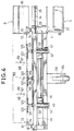
- FIG. 1 A first embodiment of the present invention will now be described as applied to a sequence of command and control signals for a robot manipulator device of a sheet metal bending press the structure of which is represented in Figures from 1 to 6; in particular, in Figure 1 there is illustrated a sheet metal bending installation 500, and the reference numeral 1 generally indicates a bending press including a die 2 and a die 3. In front of the press 1 there is a manipulator device generally indicated 4.
- a magazine On one side of the press 1 there is located a magazine with a loader device 5 and a discharge table generally indicated 6.
- An electronic microprocessor controlled unit 7 controls the operation of the manipulator device 4 and the press 1.
- the electronic unit 7 is provided with an alphanumeric keyboard 8, a video 9, and a small portable keyboard 11 (hand box) utilised in a manner which will be clarified hereinbelow.
- the loader device 5 comprises a bed 20 with an upper plane 22 on which rests a stack of flat, rectangular metal sheets 23 to be subjected to bending.
- a movable beam 24, controlled by actuators 26, carries a series of suckers 28 for lifting the sheets 23 in succession and transferring them to a horizontal position in the space between the loader device 5 and the discharge table 6, which latter is constituted by a simple bed with an inclined support plane 30.
- the plane 30 is intended, as will be seen, to receive the shaped sheets from the manipulator device 4.
- This manipulator device 4 includes a support base having feet 32 which carry a guide 34.
- the guide 34 extends parallel to the working plane of the press 1 along the whole of the lower part of the press 1, and into the space between the loader device 5 and the discharge table 6.
- an elongate carriage generally indicated 36 which is slidable parallel to the die 2, that is to say along the X-axis.
- the carriage 36 is movable along the guide 34 from a position in which it faces the press 1 to a position in which it is located between the loading device 5 and the discharge table 6.
- a servo motor 38 which is preferably numerically controlled.
- the servo motor 38 drives a toothed wheel (not shown) which cooperates with a rack (not shown) which extends along the guide 34.
- the carriage 36 supports, adjacent its ends, a pair of longitudinal guides 40 which extend parallel to the Y-axis. Each of these guides 40 is vertically slidable on the carriage 36 parallel to the Z-axis. Their movement along the Z-axis is controlled by a numerically controlled servo motor 42 carried by the carriage 36. Each guide 40 is supported by a vertical rod 44 slidable in the carriage 36. The servo motor 42 drives in unison respective toothed wheels (not shown) meshing with respective racks (not shown) supported by the rods 44.
- the guides 40 support a robust beam 46 which extends parallel to the bending zone defined by the dies 2 and 3.
- the beam 46 is supported on the guides 40 by respective slides 48 movable parallel to the Y-axis.
- Each slide 48 carries a vertical pin 50 about which the beam 46 can oscillate horizontally through a small angle.
- each slide 48 The movements of each slide 48 are controlled by a respective, numerically controlled servo motor 52 carried by the respective guide 40.
- Each servo motor 52 drives a respective worm screw (not shown) which extends within the guide 40 and which cooperates with a nut (not shown) fixed to the respective slide 48.
- the movements of the beam 46 along the Y-axis, during manipulation of the workpieces, are controlled by the two servo motors 52 acting in unison in such a way that the beam 46 moves parallel to itself.
- the press 1 is provided with a pair of alignment sensors 66 which are mounted on supports slidable along the Y-axis, and which are disposed close to the die 3.
- the sensors 66 are provided with a rod 67 which is movable parallel to the Y-axis and terminates with an end 68 adapted to detect contact with an edge of the metal sheet 23.
- the side of the beam 46 facing the press 1 carries two motor driven slides (not shown) slidable in unison and in opposite directions along the beam 46 itself; each slide carries a robust hollow projecting arm 74 extending towards the bending press 1. Each of these arms 74 carries at its free ends a respective manipulator head 10 the axis of rotation of which is common to the two heads.
- the movements of the two slides serve to cause engagement of the manipulator heads 10 with the edges of the sheet 23 and their disengagement therefrom.
- the rotations, in unison, of the two heads 10 about their axes, both for changing the attitude and the position of the manipulator pincers carried by the heads 10, are controlled by a numerically controlled servo motor.
- the head 10 comprises a square flange 90 which supports two projecting opposite cheeks 92 and 94.
- the free ends of these cheeks 92 and 94 are shaped in such a way as to constitute respective outer fixed jaws 96 and 98, of a manipulator pincer 72 and a manipulator pincer 73 respectively.
- a rod 100 Centrally between the two cheeks 92 and 94 extends a rod 100 to which is fixed a double piston.
- the piston is surrounded by a movable body 104 constituting a cylinder for the piston.
- the body 104 is movable to and fro along the rod 100.
- the disposition is such that when the pincer 73 is open the pincer 72 is closed and vice versa.
- the two diametrically opposite manipulator pincers 72 and 73 are situated eccentrically with respect to the axis of rotation of the head 10.
- the fixed jaws 96 and 98 are situated on the outline of the head, whilst the movable jaws 106 and 108 are slidable within the outline of the head 10. This disposition is the most favourable for achieving a manipulator head 10 of very small dimensions and permits the maximum possible approach of the manipulator pincers 72 and 73 to the bending zone.
- Both the fixed jaws 96 and 98 and the movable jaws 106 and 108 are replaceable in a simple and rapid manner with jaws of different dimensions, especially in width. Whilst the jaws 908 and 108 shown may be of minimum width, the maximum width of the jaws can be equal to the width of the head.
- auxiliary support device 110 For this purpose, along the beam 46 there is mounted at least one principal auxiliary support device generally indicated 110.
- This device 110 comprises a carriage 112 which is manually movable along the beam 46 and lockable on this in a desired position. If only one auxiliary device 110 is provided this position is the median position illustrated in Figure 1.
- a hollow projecting auxiliary support arm 114 is articulated on the carriage 112 about a horizontal axis parallel to the X-direction.
- an actuator (not shown) carried by the carriage 112 maintains the arm 14 in a raised position.
- the arm 114 carries an auxiliary support head 116 having two suction tubes.
- the head 116 is rotatable about an axis which coincides with the axis of rotation of the manipulator heads 10 and the auxiliary head 116 turns in unison with the manipulator heads 10.
- the head 116 carries two series of diagonally opposite lower suckers 119 and upper suckers 120 like the manipulator pincers 72 and 73 and having abutment surfaces which correspond with the gripping planes of the manipulator heads 10.
- the suckers 120 are connected, in a manner not shown, to a vacuum source (not shown).
- suckers 119 or 120 are able to support a sheet at its intermediate zone independently of the attitude of the surface of the sheet which they engage.
- the auxiliary support device 110 is utilised when forming the first bends.
- the actuator is controlled in such a way as to cause the arm 114 to descend to an inactive position.
- the auxiliary support 110 is flanked by two secondary support devices 121 which are disposed on opposite sides of the device 110 and have a similar structure.
- the devices 121 among other things have a plurality of upper suckers 123 and lower suckers 122 the function of which is analogous to that of the suckers 119 and 120.
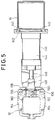
- a robust supporting column 124 is fixed to the floor on the side of the base 32 opposite that facing the press 1, which column includes two facing box-like uprights 125. Between the uprights 125 there is located a robust oscillating box-like arm 126 supported by the uprights 125 by means of a pin 128.
- a vertical actuator 130 ( Figure 2). Associated with the arm of the actuator 130 there is a pulley block 132 for a chain 134 anchored to the arm 126.
- the arm 126 carries a beam 14 which carries spaced pincers 12 at its front and is mounted so as to be rotatable through 180° at the free upper end of the oscillating arm 126.
- a double acting longitudinal pneumatic actuator 136 which controls the rotation of the beam 14 about the support axis on the arm 126 by means of a chain transmission 138.
- the structure comprising the arm 126, the beam 14 and the pincers 12 can be made to oscillate, by means of the actuator 130, between the inclined position illustrated in solid outline in Figure 2 and the vertical raised position illustrated in broken outline in Figure 2.
- FIG 2 the beam 46 and one of the support arms 74 of the manipulator heads 10 are shown in solid outline in the lowermost position of greatest advance towards the press 1, and in broken outline in the uppermost and most retracted position.
- the reference numeral 139 indicates the manipulation space within which the common axis of rotation of the manipulator head 10 and the auxiliary support head 116 can move.
- the beam 14 has a pair of longitudinal guides 140 along which are mounted four slides 142 which are manually displaceable and lockable on the guides themselves in the positions considered most convenient.
- each slide 142 has fixed to it the cylinder 144 of a double acting pneumatic actuator 146.
- the arm of the actuator 146 is indicated 148 and projects forwardly with respect to the beam 14.
- the cylinder 144 carries a bracket 150 which surrounds the arm 148 and carries a transverse pin 152.
- the pin 152 constitutes a central fulcrum for the two symmetrical jaws 154 of the auxiliary pincer 12.
- Each jaw 154 is provided with a pair of lateral rollers 156.
- the arm 148 is provided with a front plate 158 with which the rollers 156 cooperate.
- tension coil springs 160 hooked into respective cavities or seats of the plate and the jaw.
- the arrangement is such that when the actuator 146 and the plate 158 are retracted, the springs 160 maintain the pincer 12 open with the jaws 154 separated, as illustrated in solid outline in Figure 5.
- FIG 12 the interconnections between the electronic control unit 7 and the various devices connected to it and controlled by it are shown schematically.
- the electronic unit 7 controls the press 1, the manipulator device 4, the loader device 5, and the discharge table 6 (if automated with a device for removing the finished pieces from the plane 30).
- the electronic unit 7 is moreover provided with a portable keyboard 11 and a keyboard 8 utilised to create a sequence of control signals in a manner which will be explained clearly hereinbelow.
- the electronic unit 7 is finally provided with a video 9 for visualisation of the sequence of control signals, and can be connected to an external unit 480, indicated in broken outline, which can be utilised both for the generation and for the memorisation of sequences of control signals.
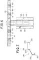
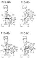
- FIG 7 there is shown the profile of a shaped workpiece 499 having six parallel bend lines 200, 210, 220, 230, 240 and 250 obtained from a flat metal sheet 23 of rectangular form by a bending cycle which will be described in detail with reference to Figures 8a to 8q.
- the bending press 1 is schematically illustrated as comprising the lower die 2 and the upper die 3.
- the die 2 is fixed, whilst the die 3 is reciprocably movable in a vertical working plane.
- the die 2 has a hollow profile with a dihedral angle and the die 3 has a complementary convex profile with a dihedral angle.
- the dihedral angle is 90° and is symmetrical with respect to the working plane.
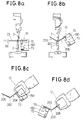
- the manipulator device 4 comprises a pair of manipulator heads 10 which carry respective manipulator pincers 72 and 73.
- These pincers 72 and 73 are illustrated in Figures 8a-8q in a different position from that illustrated in Figure 3; in particular the pincers 72 and 73 have gripper openings on the same side of the head 10 and are movable in unison and in opposition (closure and opening) with respect to one another.
- Each manipulator head 10 is mounted rotatably about an axis 150 common to the two heads.
- the heads 10 are caused to rise simultaneously until they carry the sheet 23 onto the die 2 with the rear edge of the sheet 23 coming into contact with the ends 68 of the sensors 66; in this way the sensors 66 emit a signal which indicates that the sheet 23 has reached, within the interior of the press 1, the predetermined position for the formation of the first bend 200 at the predetermined height.
- the die 2 and the die 3 are then caused to advance towards one another in such a way as to retain the sheet 23 without bending it.
- the following phase is the bending phase in which the die 3 is further lowered and forms the bend 200 in the sheet 23.
- the auxiliary pincers 12 lie in an inclined gripping plane. To permit the gripping of the sheet 23 by the auxiliary pincers 12, in their rising motion moving away from the press 1 the heads 10 have been caused to rotate in such a way as to carry the leaf 206 of the sheet 23 into correspondence with this plane. As illustrated in Figure 8c, the auxiliary pincers 12 grip the longitudinal edge of the sheet 23.
- the manipulator pincers 72 disengage from the lateral edges of the sheet 23 and move away.
- the two heads 10 are again lowered, turning about the axis 150, and advanced to bring the leaf 206 of the sheet 23 to rest on the edges of the die 2.
- the sheet 23 is rested on the die 2 in such a way that the rear edges of the leaf 206 are aligned with the ends 68 of the sensors 66 positioned along the Y axis at a height corresponding to the production of the second bend 210.
- the head 10 performs a rotation about its axis 150 and translates gripping the sheet 23 by means of the pincers 72 ( Figure 8h).
- the press 1 is opened again and the leaf 206 of the sheet 23 is inserted between the die 2 and the die 3 until the rear edge comes into contact with the sensors 66 as illustrated in Figure 8i, for the production of the fourth bend 230. Subsequently the sheet 23 is released from the pincers 72 and the press 1 forms the fourth bend 230. As can be established from Figure 8j, after the production of the fourth bend a part of the leaf 206 of the sheet 23 envelops the die 3. This prevents or renders difficult the disengagement of the sheet 23 from the die 3 during its rising movement.
- the two heads 10 gripping the sheet 23 with the pincers 72 are therefore raised and simultaneously rotated about their axis of rotation 150 during the elevation of the die 3 so as to release the sheet 23 from the die 3 (tracking).
- the auxiliary pincers 12 grip the edge of the leaf 205 of the sheet 23 ( Figure 8l) along its longitudinal edge, and the manipulator pincers 72 disengage from the lateral edges of the leaf 206; subsequently ( Figure 8m) the auxiliary pincers 12 invert the sheet 23 by rotation of the beam 14, then the manipulator pincers 72 grip the leaf 205 of the sheet 23 again, and finally the auxiliary pincers 12 open and move away.
- manipulator pincers 72 release the sheet 23 retained between the die 2 and the die 3, and the die 3 descends to the position corresponding to Figure 8o, and forms the fifth bend 240.
- the press 1 is then re-opened and the manipulator device 4 moves to the discharge table 6 where the pincers 72 release the workpiece 499 which falls onto the plane 30 of the table 6.
- the electronic unit 7 is in fact provided with a programme by which it is possible, by means of the portable keyboard 11 (hand box), or possible by means of the keyboard 8, to define a complete sequence of operating phases which can be performed by the sheet metal bending installation 500.
- the keyboard 11 is provided with a plurality of function keys 260 each of which is adapted to define a complete sequence of command and control signals for the sheet metal bending installation 500, for a respective phase in the cycle by which a shaped sheet metal profile is formed, for example of the type illustrated in Figure 7.
- These sequences of control and command signals, corresponding to each of the function keys 260, are conveniently memorised in a memory block of the electronic unit 7.
- the keys 260 are indicated with a letter “F” to define that this key is a function key, and with a number, indicated after the letter "F", to distinguish the various operating functions which can be achieved by means of the keys 260.
- the keyboard 11 (hand box), is also provided with other keys which can also be used in combination with the function keys 260 to define other instructions which can be executed by the sheet metal bending installation 500.
- the keyboard 11 includes a key 261 indicated with the symbol "MOVE” adapted to define command signal instructions for translation of the manipulator device 4 along three axes X, Y and Z.
- the "MOVE" key 261 is also able to define instructions for signals commanding rotation of the heads 10 about their common axis 150, displacement of the head 10 along the axis X, and finally rotation of the beam 14 and inclination of the arm 126.
- the "MOVE" key 261 is utilised jointly with other keys on the keyboard 11 to define a vector which comprises all the movements listed above and definable by the "MOVE" key itself.
- the (hand box) keyboard 11 includes:
- This vector can be of the form: MOVE ( ⁇ X, ⁇ Y, ⁇ Z, ⁇ A, ⁇ B, ⁇ C, ⁇ D)
- MOVE is the instruction defined by the key 261 and X, Y, Z, A, B, C and D are the numerical values inserted by means of the keys 262-268 which represent how far and in which direction the beam 46 of the manipulator 4, the heads 10, the beam 14, and the arm 126 must move with respect to an initial position.
- the key 261 can be utilised successively to create a sequence of vectors of the type: MOVE ( ⁇ X 1 , ⁇ Y 1 , ⁇ Z 1 , ⁇ A 1 , ⁇ B 1 , ⁇ C 1 , ⁇ D 1 ) MOVE ( ⁇ X 2 , ⁇ Y 2 , ⁇ Z 2 , ⁇ A 2 , ⁇ B 2 , ⁇ C 2 , ⁇ D 2 ) MOVE ( .................-2018) MOVE ( ⁇ X n , ⁇ Y n , ⁇ Z n , ⁇ A n , ⁇ B n , ⁇ C n , ⁇ D n )
- the keyboard 11 further includes a "MEM" key 269 for memorisation of the previously made key selections, and the manner of operation of this will be described in more detail below.
- Figure 9 is a flow chart illustrating the operations performed by the electronic command unit 7 to create the basic sequence of command and control signals for the bending installation 500 so as to be able then to perform the bending cycle previously described to produce the profile illustrated in Figure 7.
- the initial block 270 detects if the creation of a new sequence of operating phases has been requested by the operator, for example with the selection on the keyboard 8 or 11, or if the execution of previously memorised operating phases has been requested.
- the system passes from block 270 to block 272 which detects if a key of the keyboard 11 (hand box) has been pressed. In the negative case it remains in closed cycle in this block waiting for a key to be pressed. If a key has already been pressed, from block 2727 the system passes to a block 273 which detects if a function key 260 has been pressed. In the positive case, from the block 273 it passes to a block 274 which commands execution of the phases determined by the function key 260 which has been pressed. From block 274 it passes to a block 275 which detects if the memorisation of the selected function key has been requested by means of the key 269.
- this block detects that a function key 260 has not been pressed it passes to a block 277 which detects if the key pressed is the key 261 defining a sequence of movements. If a key has been pressed which is not a key defining a sequence of movements, it moves from block 277 onto a block 278 which commands execution of the operation requested with this key, and subsequent exit from the programme. If the block 277 detects that the key 261 defining an instruction for movement has been pressed, it passes to a block 279 which commands execution of the movement requested by means of the keys 262-268. From block 279 it then moves to a block 280 which detects if memorisation of the selected movements has been requested by means of the key 269.
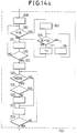
- Figures 10a and 10b are a flow chart illustrating its operation of the electronic unit 7 with the system of Figure 9, and define the sequence of command and control signals for the bending installation 500 to perform the bending cycle previously described with reference to Figures 8a-8q to obtain the workpiece 499 of Figure 7.
- This arrangement therefore has a sequence of blocks which comprise instructions for movement of the parts of the installation (heads 10, press 1, loader device 5 etc) or instructions for the operation of the installation (defined by the said function keys 260).
- the process starts initially at a block 300 which initiates the general starting procedures of the programme. From block 300 it passes to a block 301 which comprises the instructions for the signals to command the loader device 5 to take up the sheet 23 and for the lateral positioning of the bed 20 over the sliding zone of the beam 46 on the guide 34; these instructions are determined by activation of the function key 260 indicated F22 on the keyboard 11.
- a block 304 which comprises, with a previously defined "MOVE" vector, the sequence of instructions created by activation of the key 261 and keys 262 for the coarse movement signals defining the movement of the manipulator device 4 towards the bed 20 for loading the sheet 23.
- a block 307 which comprises the instructions, created by activation of the key 261 and keys 262, 263, 264, 265, 266 for the final and precise movement of the beam 46 and the gripper heads 10 of the manipulator device 4 so as to carry it and the pincers 72 into the gripping position at the edges of the sheet 23; from this block 307 it moves on to a block 308, defined by the function key F2, which comprises the instructions for the signals for commanding closure of the pincers 72 to grip the sheet 23.
- a block 310 defined by the function key F23 which comprises the instructions for separating the loader device 5 from the sheet 23 by means of disactivation of the suction from the suckers 28.
- a block 311 comprising, with the MOVE vector, the instructions for movement of the beam 46 of the manipulator 4 towards the press 1 (carrying the sheet 23); this block 311 is followed by a block 470, defined by the function key F21 which comprises the instructions for command signals for the sensor positioning procedure (sensors 66) which define the depth of alignment of the sheet 23 into the press 1 ( Figure 8a).
- the block 470 is followed by a block 471 which comprises the instructions for the command signals for moving the heads 10 and the beam 46 of the manipulator device 4 to bring the rear edge of the sheet 23 up to the sensors 66. From block 471 it passes to a block 312, defined by the function key F17, which comprises the instructions for signals commanding the procedure for alignment of the sheet 23 in the press 1, in the position for forming the first bend 200, and lowering of the die 3 into contact with the sheet 23 to retain it in position.
- the block 312 is followed by a block 313, defined by function key F1, which comprises the instructions for the command signals for opening the pincers 72.
- a block 314 which comprises the instructions for command signals for withdrawing the manipulator heads 10 from the manipulation space 139.
- block 316 From block 316 it passes to a block 317 which comprises the instructions for the command signals for movement of the manipulator head 10 towards the bent sheet 23.
- a block 319 which comprises the instructions for command signals for the final and precise movement of the manipulator device 4 in such a way that the manipulator heads 10 arrive at a position such as to grip the folded sheet 23 ( Figure 8b). Subsequently it passes from block 319 to a block 320, defined by function key F2, comprising the instructions for command signals for closure of the pincers 72 to grip the sheet 23.
- the block 324 is followed by a block 325, defined by function key F1, which comprises the instructions for the command signals for opening the pincers 72 to release the sheet 23.
- a block 326 which comprises the sequence of instructions for command signals to withdraw the device 4 from the manipulation space 139.
- the block 327 is followed by a block 330 defined by function key F3, which comprises the instructions for opening the pincers 73.
- the block 334 is followed by a block 335, defined by function key F21, which comprises the instructions for the signals to command the procedure for positioning the sensors 66 ( Figure 8e).
- the block 335 is followed by a block 336 which comprises the instructions for the command signals for movement of the heads 10 and the beam 46 of the manipulator device 4 to cause the rear edge of the sheet 23 to approach the sensors 66.
- block 336 From block 336 it passes to a block 337 defined by function key F17, which comprises the instructions for command signals for the procedure for alignment of the sheet 23 in the press 1, and gripping it between the dies 2 and 3.
- function key F17 which comprises the instructions for command signals for the procedure for alignment of the sheet 23 in the press 1, and gripping it between the dies 2 and 3.
- the block 337 is followed by a block 338, defined by function key F3, which comprises the instructions for signals commanding opening of the pincers 73.
- block 340 which comprises the instructions for command signals for withdrawal of the heads 10 of the device 4 from the bending zone.
- block 342 which comprises the instructions for the command signals for movement of the heads 10 of the manipulator device 4 towards the sheet 23, which now has the two bends 200 and 210.
- the block 342 is followed by a block 343 which comprises the instructions for signals commanding the final and precise movement of the manipulator device 4 in such a way that the pincers 73 of the manipulator head 10 are moved to a position adapted to grip the leaf 205 of the bent sheet 23.
- block 346 From block 346 it passes to a block 347 which comprises the instructions for command signals for controlling movement of the manipulator heads 10, for repositioning the metal sheet 23 in the press 1.
- the block 347 is followed by a block 350, defined by function key F21, which comprises the instructions for command signals for controlling the procedure for repositioning the sensors 66, for achieving the third bend 220 ( Figure 8g).
- the block 350 is followed by a block 351 which comprises the instructions for signals commanding the movement of the head and the beam 46 of the manipulator device 4 to bring the rear edge of the sheet 23 up to the sensors 66.
- the block 351 is followed by a block 353, defined by the function key F3, which comprises the instructions for signals commanding opening of the pincers 73.
- block 354 which comprises the instructions for signals commanding disengagement of the heads 10 of the device 4 from the bending zone.
- the block 355 is followed by a block 356 defined by the function key F1, which comprises the instructions for the signals commanding opening of the pincers 72 to prepare them for the subsequent gripping of the sheet 23.
- block 357 which comprises the instructions for signals commanding movement of the heads 10 of the manipulator device 4 towards the sheet 23, which now has three bends 200, 210, 220.
- the block 357 is followed by a block 359 which comprises the instructions for the command signals for the final and precise movement of the manipulator device 4 in such a way that the pincers 72 of the manipulator heads 10 are moved into a position adapted to grip the leaf 205 of the bent sheet 23.
- a block 365 which comprises the instructions for command signals for the movement of the manipulator heads 10, for repositioning the leaf 206 of the metal sheet 23 in the press 1.
- the block 365 is followed by a block 366, defined by function key F21, which comprises the instructions for command signals for the procedure for repositioning the sensors 66 for forming the fourth bend ( Figure 8i).
- the block 366 is followed by a block 367, defined by the function F17, which comprises the signals for commanding the procedure for alignment of the sheet 23 in the press, and gripping it between the dies 2 and 3.
- the block 367 is followed by a block 368, defined by the function key F1, which comprises the instructions for the signals for commanding opening of the pincers 72.
- From block 368 is passes to a block 370 which comprises the instructions for command signals for withdrawal of the heads 10 of the device 4 from the bending zone.
- block 373 which comprises the instructions for the command signals for movement of the heads 10 of the manipulator device 4 towards the sheet 23, which now has four bends 200, 210, 220 and 230.
- the block 373 is followed by a block 375 which comprises the instructions for command signals for the final and precise movement of the manipulator device 4 in such a way that the pincers 72 of the manipulator heads 10 are disposed in a position suitable for gripping the leaf 206 of the bent sheet 23.
- block 382 which comprises the instructions for command signals for withdrawal of the device 4 from the manipulation space 139.
- the block 450 is followed by a block 451, defined by function key F14, which comprises the instructions for the command signals for opening the auxiliary pincers 12.
- a block 452 which comprises the instructions for the command signals for movement of the head 10 towards the press 1.
- the block 452 is followed by a block 386, defined by function key F21, which comprises the instructions for signals commanding the procedure for a new positioning of the sensors 66 ( Figure 8n).
- the block 386 is followed by a block 387, defined by the function key F17, which comprises the instructions for signals commanding the procedure for alignment of the sheet 23 in the press 1 and gripping it between the dies 2 and 3.
- the block 387 is followed by a block 388, defined by the function key F1, which comprises the instructions for signals commanding opening of the pincers 72.
- block 390 which comprises the instructions for signals commanding withdrawal of the heads 10 of the device 4 from the bending zone.
- the block 391 is followed by a block 460 which comprises the instructions for command signals for movement of the heads 10 of the manipulator 4 towards the sheet 23 which now has five bends 200, 210, 220, 230 and 240.
- the block 460 is followed by a block 392 which comprises the instructions for signals commanding the final and precise movement of the manipulator device 4 in such a way that the pincers 72 of the manipulator heads 10 are disposed in a position adapted to grip the leaf 206 of the bent sheet 23.
- the block 461 is followed by a block 394 which comprises the instructions for signals commanding the movement of the manipulator heads 10, and the repositioning of the metal sheet 23 in the press 1 ( Figure 8p).
- block 394 From block 394 it passes to block 395, defined by function key F21, which comprises the instructions for signals commanding the procedure for the new positioning of the sensors 66.
- the block 395 is followed by a block 396, defined by the function key F17, which comprises the instructions for the signals commanding the procedure for aligning the sheet 23 in the press 1, and gripping it between the dies 2 and 3.
- the block 396 is followed by a block 397, defined by the function key F1, which comprises the instructions for signals commanding the opening of the pincers 72.
- block 400 which comprises the instructions for the signals commanding withdrawal of the heads 10 of the device 4 from the bending zone.
- a block 402 which comprises the instructions for the command signals for movement of the heads 10 of the manipulator device 4 towards the finished workpiece 499.
- the block 402 is followed by a block 404 which comprises the instructions for the command signals for final and precise movement of the manipulator device 4 in such a way that the manipulator heads 10 are disposed in a position adapted to grip the bent workpiece 499.
- a block 410 which comprises the instructions for command signals for the movement of the manipulator device 4 to the position for transforming the workpiece 499 to the discharge table 6.
- the block 410 is followed by a block 411, which comprises the instructions for command signals for the final and precise movement of the manipulator device 4 in such a way that one side of the workpiece 499 rests on the inclined support plane 30 of the discharge table 6.
- the sequence of command signals is treated by the electronic unit 7, with the system constituting the subject of the present invention, which provides for increasing the working speed of the sequence itself.
- the electronic unit 7 comprises, as illustrated in Figure 13, a first block 501 which checks if a sequence of command and control signals for the manipulator device 4 and the system 500 already exists; if this sequence does not exist it exits from the programme, on the other hand if this sequence does exist it passes to a second block 502 which effects a first increase in the speed of the sequence.
- the block 502 acts on the instructions for displacement command signals for the manipulator device 4, defined conveniently with the "MOVE” key, and initially checks if the "MOVE” type instructions are isolated, or if they are grouped in a sequence. If the "MOVE” instructions are isolated they are not modified. If instead these "MOVE" type instructions are grouped in a set of two or move consecutive instructions the block 502 associates each instruction of the group with the following one.
- the block 502 associates together the pairs of numerical values X, Y, Z, A, B, C, D of two consecutive "MOVE" instructions (which correspond to the position assumed by the heads 10 and the arm 126 with the beam 14 in a first and in a second position) in such a way as to approximate the trajectory passing through the said positions, and therefore to reduce the time taken for the displacement.
- This association operation is repeated for all the pairs of successive "MOVE" instructions in such a way that a movement of the heads 10 which has been defined by means of a complex trajectory constituting the sum of individual trajectories between a number of positions, is speeded up in that each individual trajectory is modified and recorded with the adjacent trajectories; it is therefore not necessary to have to stop in the intermediate positions, but only to stop in the final position, defined by the last "MOVE" instruction of the group, which has not been modified.
- the block 502 further determines, before the said association between the "MOVE” instructions, a testing of the successive "MOVE” instructions at each bending phase of the press 1, and generates, before the sheet 23 is taken again by the heads 10, a synchronisation and control signal obtained after the bend execution command so as to allow the correct completion of the bending phase and subsequent secure gripping by the heads 10 without having to wait for completion of the bending phase before initiating the movement of the heads 10 towards the sheet 23.
- a positive condition detected by the block 510 it moves on to a block 560 which associates, to the block for commanding execution of a bend, conveniently defined by the function key F18, the commencement of a parallel sequence for obtaining this synchronisation and control signal T3, and then moves onto a block 515 which detects if the instruction under examination commands the final and precise positioning of the pincers 72 or 73 of the heads 10 at the sides of the sheet 23, which is detectable for example by means of the value of the dimension B of the "MOVE" instruction by referring it to the positioning of the heads 10 along the X-axis with respect to a central reference point on the beam 46, and testing if this value B is less than a value B1; if not this indicates that the instruction under examination still relates to a displacement before this final and precise positioning of the pincers 72 or 73 of the heads 10 against the edges of the sheet 23 so that it moves on to a block 516 which commands analysis of a subsequent instruction of the flow chart of Figure 10a and 10b,
- Block 517 there is therefore introduced a block 517' to command the delay in the signal T3, between the blocks 317 and 319 of Figure 10a, as can be seen in the final block diagram obtained according to the present invention and illustrated in Figures 15a and 15b, and similarly blocks 517' are inserted between the other pairs of corresponding blocks 342-344, 357-359, 373-375, 460-392, 402-404.
- the block 560 links the commencement of the sequence to obtain the signal T3 to each of the blocks 315, 341, 355, 371, 391 and 401 for commanding the formation of a bend.
- the block 513 then in turn commands analysis of the first instruction of the flow chart illustrated in Figures 10a, 10b then moves on to a block 520 which detects if this instruction is of the "MOVE" type, and if so moves on to a block 521 which detects if this instruction is isolated, that is to say relates to a displacement between two individual points: if not it moves on to a block 522 which associates this "MOVE" instruction to the subsequent "MOVE" instruction as already indicated, and then moves on to a block 523 which commands the analysis of a subsequent instruction of this block diagram of Figures 10a and 10b. It also moves directly to this block 523 following detection of the negative condition of the block 520 or the positive condition of the block 521. From block 523 it moves to block 524 which detects if this instruction is the last one of the cycle. If it is not it returns to block 520, whilst if it is it exits from block 502.
- the block 503 modifies and optimises the sequences of command signals relating to the movement of the manipulator device 4 and the loader device 5, in such a way that when the manipulator device 4 is positioned to release the finished workpiece 499 on the discharge table 6 the initiation of the new phase of loading a metal sheet 23 from the magazine 5 is commanded and, moreover, before the gripping of the new sheet 23 with the heads 10 there is a delay in the synchronisation and control signal T2 following the command for the sheet 23 to be lifted by the loading device 5 so as to allow the correct positioning of the sheet 23 over the beam 46 by the loading device 5.
- a first block 529 which commands analysis of the first instruction of the flow chart illustrated in Figures 10a and 10b, which then moves on to a block 530 which detects if this instruction relates to the command to form a final bend in the sheet 23, defined by the function key F18; in the negative case it moves on to a block 531 which commands analysis of a subsequent instruction of this block diagram of Figures 10a and 10b, and then returns to block 530, whilst in the positive case it moves on to a subsequent block 532 which detects if the instruction under examination commands the final and precise positioning of the manipulator device 4 in such a way that the workpiece 499 is lowered on to the inclined plane 30 of the discharge table 6, detectable for example by means of the value of the dimension Z of the move instruction referring to the positioning of the height of the heads 10, and checking if this value Z is greater than a value Z1; in the negative case this indicates that the instruction under examination still relates to a displacement preceding this final
- block 535 determines the delay in the signal T2 before the final and precise movement of the beam 46 and the gripper heads 10 of the manipulator device 4 to the grip position to grip the sides of the sheet 23, which is defined by the block 307 of Figure 10a.
- this block 535 there is therefore inserted a block 535' for commanding a dealy in the signal T2, after the block 412 and before a block 307, as can be seen in the final flow chart according to the present invention and illustrated in Figure 15b; this block 307 is then followed by a block 308 and thereafter, as illustrated in Figure 10a, by a new bending cycle.
- From block 535 it exits from block 503, and from block 503 ( Figure 13) it exits from the system of the present invention for increasing the speed of operation of the sequence of command and control signals for the bending installation 500.
- the arrangement of the second embodiment differs from that of the first embodiment in the arrangement shown in Figs. 16a, 16b-22.
- a sequence of command signals of the type described above, and defined for a given bending installation is modified automatically by the electronic unit 7 on the basis of the dimension of the bending installation on which it effectively operates.
- a sequence of command signals for example those utilised to form the profile illustrated in Figure 7, is created by controlling a bending installation having a given configuration utilised as a reference for all the other bending installations; this specimen bending installation will be indicated hereinafter with the term "master” and all the other similar bending installations assembled subsequently will be indicated with the term "slave”.
- the second embodiment of the present invention operates to perform a series of tests on the "master” installation and on the "slave” installation, to detect by how much certain dimensions of the configurations comprising parts of the "slave” installation differ from the corresponding dimensions of the "master” installation, and to modify the sequence of command signals utilised on the "slave” installation (but defined for the "master” installation) in such a way that this sequence of command signals controls the "slave” bending installation in an absolutely correct and precise manner.
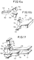
- a first and a second metal specimen block are utilised, illustrated in Figures 16a and 16b, and indicated with the numerals 702 and 707, which are respectively gripped by the auxiliary pincers 12 and by the pincers 72 and 73 of the heads 10, and serve as abutment elements for the detection of various dimensions of these installations, as will be described hereinbelow.
- the first specimen block 702 includes a first flat portion 703 shaped as a rectangular parallelepiped from one end of which extend two portions 704 of greater thickness, which terminate with flat front surfaces 705. These appendices 704, moreover, are inclined with respect to the portion 703 by an angle gamma ( ⁇ ) equal to about 130° so as to be divergent from one another.
- ⁇ angle gamma
- the second specimen block 707 comprises a flat parallelepiped main portion 708 from the front of which extends a coplanar projection 709 of reduced thickness which terminates with a flat front surface 710.
- the portion 708 has a second portion 711, which extends laterally of the portion 708 in a direction perpendicular to the first projection 711, and terminates with a flat front face 712 which functions as an abutment element in a manner which will be clarified hereinbelow, moreover this portion 711 has an end part 714 of greater thickness at the top, the surface of which will also be utilised as will be seen in detail.
- the blocks 702 and 707 are firmly gripped, respectively, by an auxiliary pincer 12 of the auxiliary support group 124, and by a pincer 72 of the manipulator heads 10; in particular, the jaws 154 of the pincer 12 close on the free end faces of the flat portion 703 of the block 702, and the jaws 96 and 106 of the pincer 72 close on the faces of the main portion 708 of the block 707.
- auxiliary support group 124 and the manipulator device 4 are then moved, conveniently by means of the keyboard 11 and the associated movement keys as described hereinabove, in such a way that the box-like arm 126 is tilted down towards the press 1, and consequently the beam 14, which carries the auxiliary pincers 12 is likewise lowered so that the axis of the upper portion 704 of the block 702 is located horizontally; the manipulator head 10 which carries the block 707 is in turn displaced until it approaches the block 702, and the flat front face 712 of the block 707 comes into contact with the side wall of the portion 704 with the upper front edge of the end wall 714 fitting together with the upper side edge of the portion 704.
- an operator imparts to the loader device 5 the instruction to load a sheet 23 so that the suckers 28 grip this sheet 23 which is then raised by the beam 24, and positioned between the loader device 5 and the discharge table 6 in the gripping zone of the heads 10.
- the operator for example still by means of the keys on the keyboard 11, causes the beam 46 to move along the X axis towards the magazine 5, and causes the head 10 carrying the block 707 to move, as has already been described in the first detection configuration, until the upper front edge of the end wall 714 of the block 707 comes into contact with the lateral edge of the sheet 23 (which is rectangular) parallel to the Y axis ( Figure 18a) with the central axis of the upper wall of this part 714, coincident with the central axis of the sheet 23 (along the X axis).
- This second detection configuration can also be effected with a pair of blocks 707 carried by the pair of heads 10 against the parallel lateral edges of the sheet 23 ( Figure 18b).
- the dimensions X, Y, Z, A, B of this second configuration and which identify the position of the sheet 23, and consequently of the supporting loading device 5, with respect to the manipulator device 4, are also memorised as will be described below.
- an operator again conveniently utilising the keyboard 11, moves the beam 46 until the heads 10 are located in front of the discharge table 6. Subsequently the heads 10 which carry a respective block 707 as already illustrated for the preceding detection configurations, are raised and caused to rotate in such a way that the block 707 is located in front of the support bed 30 with the projection 709 facing towards this bed 30 and positioned on parallel inclined planes.
- Figure 20 there is illustrated in detail a flow chart of a first operating stage of the system according to the present invention, conveniently effected with a command and control unit 7 of the specimen installation, in which the dimensions (X, Y, Z, A, B, C, D) relating to the predetermined detection configurations and described hereinabove with reference to Figures from 14 to 16 are memorised for this "master" specimen bending installation 500.
- this block 731 can preliminarily present on the video 9 a schematic illustration such as that shown in Figure 17, which serves as a guide for the operator for the configuration which must be achieved.
- a block 732 analogous to block 731 it passes to a block 732 analogous to block 731 which, after the second predetermined detection configuration has been reached ( Figure 18a) conveniently preliminarily shown on the video 9, commands the acquisition of the second set of dimensions which define the position of the loader device 5 with respect to the manipulator device 4 of the master installation.
- the block 733 is followed by a block 736 which provides for regrouping of the said first, second and third sets of dimensions in a form which can be extracted from the electronic unit 7.
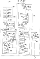
- FIG 21 there is illustrated in detail a flow chart of a second operating stage of the system of the present invention, conveniently put into effect with the command and control unit 7 of the slave installation to be tested, in which the dimensions (X, Y, Z, A, B, C, D) relating to the three predetermined detection configurations described hereinabove with reference to Figures from 17 to 19 are detected in this "slave" installation and memorised. These dimensions are then compared with the previously detected corresponding dimensions of the "master” installation, and there is then performed, in an automatic manner, an adaptation of the sequence memorised in a sample installation of the command and control signals defining a bending cycle for the said installation.
- the dimensions X, Y, Z, A, B, C, D
- first block 740 which tests if the three sets of "master” installation dimensions for the three configurations defined hereinabove have been already memorised in the electronic unit 7 of the assembled “slave” installation 500. In the negative case it exits from this stage, whilst in the positive case it passes from block 740 to a block 731', analogous to the block 731 of Figure 20, which, after the first predetermined detection configuration has been reached by the "slave” installation ( Figure 17) commands, by means of a key of the keyboard 11 selected by an operator, efffects the acquisition in a memory block of the unit 7 of the "slave” installation 500, of a first set of dimensions which define the position of the auxiliary support unit with respect to the manipulator device 4.
- this block 731' can also preliminarily present to the operator, on the video 9, a schematic illustration of the detection configuration which must be reached.
- a block 732' analogous to the block 732 of Figure 20, which after the second predetermined detection configuration has been reached by the slave installation ( Figure 18a) commands the acquisition of the second set of dimensions which define the position of the loader device 5 with respect to the manipulator device 4 of the slave installation.
- the block 733' is followed by a block 746 which provides for monitoring the compatibility of the dimensions of the "master” installation with those of the "slave” installation indicative of the correct assembly of the "slave” installation.
- This block 746 tests by how much the dimensions of the "master” in each of the three detected configurations differ from the corresponding dimensions of the "slave” installation, and if this difference exceeds predetermined limit values previously defined and memorised in the electronic unit 7 the block 746 provides a display on the video 9 of the dimensions exceeding the normal, and activates an acoustic alarm signal so that the operator can arrange for rectification of the assembly of the bending installation 500.
- the block 747 determines the end of the dimensional testing stage according to the present invention, whilst on the other hand if all these differences are less than the limit values it passes to a block 748 which acts to effect automatic correction of a memorised sequence defined on a specimen system for the command and control signals defining a bending cycle to be performed on the "slave" installation 500.
- the block 748 of Figure 21 is illustrated in detail in Figure 21. It starts with a block 751 which recalls from the memory of the electronic unit 7 the corresponding dimensions for the three predetermined detection configurations of the "master” and “slave” installations, compares them and finally calculates the associated differences; in particular a first block 900 calculates the differences X1, Y1, Z1, A1, B1, C1, D1 between the dimensions X, Y, Z, A, B, C memorised by the blocks 731 and 731' in the first detection configuration, a second block 901 calculates the differences X2, Y2, Z2, A2, B2, C2, D2 between the dimensions X, Y, A, B, C, D memorised by the blocks 732 and 732' in the second detection configuration, and a third block 902 calculates the differences X3, Y3, Z3, A3, B3, C3, D3 between the dimensions X, Y, Z, A, B, C, D memorised by the blocks 733 and 733' in the third detection configuration.
- a block 752 which re-examines the created sequence of command signals (for example of the type described with reference to Figures 10a and 10b) and searches within this sequence of instructions for command signals produced with the MOVE key and thus expressed in the form MOVE ( ⁇ X, ⁇ Y, ⁇ Z, ⁇ A, +B, +C, +D), and relating to the displacement of the manipulator device 4 in proximity to the loading device 5;
- the block 752 thus modifies all the signals expressed with the MOVE key in which the variable X is greater than a predetermined numerical reference value X 0 (for example X ⁇ 3500), which indicates that the manipulator device 4 is located close to the loading device 5, and this block 722 modifies the values of these movement command instructions on the basis of the differences X2, Y2, Z2, A2, B2, C2 determined by the block 901 and representative of the differences between the dimensions of the "master” and "slave” installations for the movement instructions relating to this loading stage.
- a first block 905 which commands the analysis of the first instruction of the flow chart illustrated in Figures 10a and 10b and formed as described, then moves on to a block 906 which detects if this instruction relates to the command for positioning the heads 10 against the sheet 23, carried by the loading device 5, which is detectable by means of the value of the dimension X of the "MOVE" instruction, i.e. by testing if this value X is greater than a value X 0 .
- the block 753 searches in the previously memorised sequence of command signals those command signals indicative of a commencement of utilisation of the auxiliary support group 124 and obtained for example by means of the function key F13. Once this command signal is found the Y and Z values of the "MOVE" type command signal which immediately precedes the command signal formed utilising the function key F13 are memorised.
- block 910 which tests if the instruction of the flow chart of Figures 10a and 10b under examination relate to the command for initiation of the use of the auxiliary support group 124 (determined by the function key F13); in the negative case it moves on to block 911 which commands analysis of a subsequent instruction of this flow chart of Figures 10a and 10b, and then moves on to a block 912 which, in an analogous manner to block 906, detects if this instruction relates to the command for positioning the heads 10 with the sheet 23 at the discharge table 6, this being detectable by means of the value of the dimension X of the "MOVE" instruction, and testing if this value X is greater than a value X 0 ; in the negative case this indicates that the instruction under examination still relates to an earlier stage or displacement than this final positioning of the heads 10 with the sheet 23 at the discharge table 6 so that it returns to the block 910, whilst in the positive case it moves on to a block 913 the operation of which will be described in detail hereinbe
- a block 914 which commands memorisation of the Y and Z values of the "MOVE" type command signal which immediately precede the command signal relating to the block 910.
- a block 915 which commands analysis of a previous instruction defined in this flow chart of Figures 10a and 10b, and then to a block 916 which detects if this previous instruction is of the "MOVE" type and in the negative case it exits from block 753 and moves on to a subsequent block 754.
- a positive condition detected by the block 916 it moves on to a block 917 which detects if this movement instruction under examination has Y and Z values which differ from the Y and Z values memorised by the block 914 by an amount less than a respective predetermined maximum limit Y 0 and Z 0 : in the negative case (movement beyond this predetermined field) it exits from block 753 and moves to a subsequent block 754, whilst in the positive case it moves on to a block 918 which imposes on the instructions under examination, for each dimension of the command signal (X; Y; Z; A; B) a modification by a corresponding value X1; Y1; Z1; A1; B1; C1; D1 determined by the block 900, and then returns to the block 915 for continuation of the possible modification of all the preceding succession of movement instructions.
- the block 754 searches in the sequence of previously memorised command signals for command signals indicative of the termination of the utilisation of the auxiliary support group 124, and obtained for example by means of the function key F14. Once this command signal is found the dimensions of all the "MOVE" type command signals which lie between the beginning and the end of this use of the auxiliary support group 124 are changed, and these values of the command signals (X, Y, Z, A, B, C, D) are modified on the basis of the corresponding differences X1, Y1, Z1, A1, B1, C1, D1 determined by the block 900 and representative of the differences between the "master” and “slave” installations for the working stages as already described.
- block 554 has a block 925 which tests if the instruction of the flow chart of Figures 10a and 10b under examination relates to the command for the end of the use of the auxiliary support group 124 (determined by the function key F14); in the negative case it moves on to a block 926 which commands the analysis of a subsequent instruction in this flow chart of Figures 10a and 10b, and then returns to the block 925.
- a block 930 which detects if the instruction of the flow chart of Figures 10a and 10b under examination relate to the command to commence utilisation of the auxiliary support unit 124 (determined by the function key F13); in the negative case it returns to the block 927 which commands the analysis of a preceding instruction in the flow chart of Figures 10a and 10b, whilst in the case of a positive condition detected by the block 930, and thus indicative that the modification has been made for all the movement instructions lying in the field of use of the auxiliary support group 124, it exits from block 754 and moves on to a block 755 which, splitting off from the command signal indicative of the end of utilisation of the auxiliary support group 124, defined for example by the function key F14, commands the memorisation of the Y and Z values of the "MOVE" type command signal which immediately follows this command signal formed utilising the function key F14.
- block 755 has a block 931 which commands the analysis of a subsequent instruction of the flow chart of Figures 10a and 10b, and then moves on to a block 932, which, in a manner analogous to the block 925, tests if the instruction under examination of the flow chart of Figures 10a and 10b relate to the command for the end of utilisation of the auxiliary support group 124 (determined by the function key F14); in the negative case it moves on to a block 933, analogous to block 926, which commands analysis of a subsequent instruction of the flow chart of Figures 10a and 10b, and then returns to the block 932.
- a positive condition detected by the block 932 that is to say indicative of the command for the end of the use of the auxiliary support group 124, it moves on to a block 934 which commands the memorisation of the Y and Z values of the "MOVE" type command signal which immediately follows the command signal detected by the block 932. From block 934 it moves to a block 935 which commands the analysis of a following instruction defined in the flow chart of Figures 10a and 10b, and then to a block 936 which detects if this following instruction is of the "MOVE" type, and in the negative case it exits from block 755 and moves to a subsequent block 937.
- a positive condition detected by the block 936 it moves on to a block 938 which detects if this movement instruction under examination has Y and Z values which differ from the Y and Z values memorised by the block 934 by an amount less than a respective predetermined maximum limit value Y 0 and Z 0 : in the negative case (movement beyond this predetermined range) it exits from block 755 and moves on to block 937, whilst in the positive case it moves to a block 939 which imposes on the instruction under examination, for each value of the command signal (X, Y, Z, A, B ...) a modification by a corresponding value (X1, Y1, Z1, A1, B1, C1, D1) determined by the block 900, and then returns to the block 935 to continued with possible modifications on all the following movement instructions in succession.
- the block 937 detects if the instruction under examination relates to the command for positioning the heads 10 with the sheet 23 over the discharge table 6, this being detectable by means of the value of the dimension X in the "MOVE" instruction, and testing if this value X is greater than a value X 0 ; in the negative case this signifies that the instruction under examination still relates to a stage of a displacement earlier than this final displacement of the heads 10 with the sheet 23 over the discharge table 6 so that it returns to the block 753 for the continuation of the correction of the movement instructions relating to other possible working stages between the manipulator device 4 and the auxiliary pincers 12; whilst in the positive case it moves to the block 913 which imposes the modification, in the sequence of movement command instructions for which X remains greater than X 0 , by corresponding amounts equal to the values X3, Y3, Z3, A3, B3 ... determined by the block 902, and then exits from the block 748 and from the stage of automatic correction of the instructions for the working cycle according to the present invention.
- the system of the present invention is able, by detecting of the coordinates of the position of the manipulator device in three predetermined configurations, and by comparing them with the corresponding coordinates of analogous configurations on the specimen system, to test if the configuration of the assembled installation is correct, and of warning the operator, and moreover, in the case of correction of this assembled configuration, the system of the present invention is able automatically to adapt the sequence of movement command and control signals dimensionally for this manipulator device, which signals were defined on the specimen installation, taking into account the small dimensional differences which inevitably exist between the two installations.
- the detection of the dimensions of the position of the manipulator device in the new installation and the comparison with the dimensions of the analogous configurations on the specimen installation are effected in three predetermined configurations which are those relating to the working stages of the heads of the manipulator device respectively with the auxiliary support pincers, with the loading magazine and with the discharge table, and only those sequences of command and control signals for movements of this manipulator device which are close to these working stages are automatically dimensionally adapted so that only in correspondence with these precise stages of movement is it necessary to obtain exact correspondence between the values of the movement instructions as defined on the specimen installation and the values effective on the actual installation.
- function keys 260 of the keyboard 11 can be selected in pairs, or together with keys having a different significance.
- the flow chart illustrated in Figure 10 can be achieved with an external programming unit 480 independently from the electronic unit 7, this external unit also being provided with function keys similar to the keys 260, which define the various previously described working phases, which are then memorised in the unit 7 by direct connection (by cable) or indirect connection (with magnetic supports etc) for execution as a production cycle.
- the unit 7 in the flow chart of Figure 9 from the block 270 directly commands the execution of the cycle with the block 271.
- the associated sequences of command and control signals described and effected by the blocks 502 and 503 can be made only partially, or combined differently; moreover, with reference to Figure 10a, the positioning command of the sensors 66 for reference in positioning the sheet 23 between the dies 2 and 3 (conveniently defined by the function key F21) can also be associated with command instructions for movement of the heads 10 (with the sheet 23 gripped thereon) towards the press 1, so as to be achieved simultaneously.
- the commands for association of phases of the operation can be determined by detection of positions achieved by the movable elements of the system, or for example by the selections effected on the function keys in the creation of the basic sequences of command and control signals.
- the flow chart illustrated in Figures 10a and 10b can also be achieved with an external programming unit 480 independent from the electronic unit 7, and then speeded up with the system of the present invention still in this outer unit 480, and then memorised in the unit 7 to be performed as a production cycle.
- the effective speeding up system of the present invention can be utilised for sheet metal bending installations having a form and operation different from that described, and also not provided with function keys as previously illustrated.
- the dimensional testing and automatic adaptation system of the present invention can, finally, be utilised for sheet metal bending installations having a different form and operation from that described.
Landscapes
- Engineering & Computer Science (AREA)
- Mechanical Engineering (AREA)
- Physics & Mathematics (AREA)
- General Physics & Mathematics (AREA)
- Automation & Control Theory (AREA)
- Human Computer Interaction (AREA)
- Manufacturing & Machinery (AREA)
- Robotics (AREA)
- Bending Of Plates, Rods, And Pipes (AREA)
- Numerical Control (AREA)
- Manipulator (AREA)
Claims (11)
- Vorrichtung zum Steuern einer Blechbiegeanordnung (500), mit:
einer Biegepresse (1);
einer Handhabungsvorrichtung (4) zum Einführen tafelförmiger Werkstücke in die Biegepresse (1) und zum Herausnehmen der Werkstücke aus der Biegepresse (1);
einer elektrischen Einheit (7) zur Steuerung der Biegepresse (1) und der Handhabungsvorrichtung (4);
einer Eingabevorrichtung (260-268) zur Eingabe einer ersten Befehlssequenz, die Befehle zur Steuerung des Betriebes der Biegepresse (1) und Befehle zur Steuerung des Betriebes der Handhabungsvorrichtung (4) aufweist,
dadurch gekennzeichnet, daß
die elektrische Einheit (7) weiterhin aufweist:
Mittel (510) zur Feststellung von Biegebefehlen innerhalb der ersten Befehlssequenz,
Mittel (515, 516), die für jeden festgestellten Biegebefehl (315) die nachfolgenden Handhabungsbefehle (316, 317, 319) untersuchen, und zum Auffinden eines bestimmten Handhabungsbefehls (319) unter den nachfolgenden Handhabungsbefehlen, aufgrund dessen Ausführung die Handhabungsvorrichtung (4) eine vorgegebene Stellung zum Greifen eines Werkstückes nahe der Biegepresse (1) erreicht,
Mittel (517) zur Erzeugung einer Zeitverzögerung, die eine Dauer (T3) besitzt, um die die Ausführung des bestimmten Handhabungsbefehles (319) zu verzögern ist, um eine Synchronisation zwischen dem Ende eines durch den Biegebefehl (315) gesteuerten Biegeschrittes und dem Beginn eines durch den bestimmten Handhabungsbefehl (319) gesteuerten Handhabungsschrittes zu erzielen,
und Mittel (502) zur Erzeugung einer zweiten Befehlssequenz, die die erzeugten Verzögerungszeiten (517') enthält, und die schließlich den Betrieb der Blechbiegeanordnung (500) steuert. - Vorrichtung nach Anspruch 1, bei der die Eingabevorrichtung aufweist:
eine erste Eingabevorrichtung (F18) zur Eingabe der Biegebefehle (315) zur Ausführung von Biegungen an einem Werkstück durch die Biegepresse (1); und
zweite Eingabevorrichtungen (261, 262, 263, 264) zur Eingabe eines Handhabungsbefehles (317) zum Bewegen des Handhabungsroboters (10) von einer Standby-Stellung zu einer Stellung nahe der Biegepresse (1), wobei in der Standby-Stellung der Handhabungsroboter bereitsteht, während eine Biegung an dem Werkstück durchgeführt wird,
wobei durch die zweiten Eingabevorrichtungen (261, 262, 263, 264) nach dem Handhabungsbefehl (317) ein anderer Handhabungsbefehl (319) eingegeben werden kann zur Bewegung des Handhabungsroboters (10) von einer Stellung nahe der Biegepresse zu einer Stellung, in der der Handhabungsroboter (10) das zwischen einem Stößel (3) und einem Gesenk (2) der Biegepresse (1) geklemmte Werkstück greifen kann, nachdem der Biegeschritt beendet ist. - Vorrichtung nach Anspruch 1 oder 2, dadurch gekennzeichnet, daß die Eingabevorrichtungen eine Vielzahl von selektiv betätigbaren Funktionstasten (260) aufweisen, wobei jede Funktionstaste (F18 bis F24) eine vorgegebene Betriebssequenz der Biegeanordnung repräsentiert, und die Funktionstasten eine Taste (F18) zur Eingabe des Befehles (315) zum Ausführen des Biegeschrittes aufweisen, und die zweiten Eingabevorrichtungen (261 bis 268) für jeden Freiheitsgrad der Handhabungsvorrichtungen der Biegeanordnung (500) eine Taste (262 bis 268) und eine mit diesen gemeinsam zu betätigende Biegungstaste (261) aufweist, zur Erzeugung von Verschiebungsbefehlen zur individuellen translatorischen und rotatorischen Bewegung jeder der Handhabungsvorrichtungen.
- Vorrichtung nach einem der Ansprüche 1 bis 3, gekennzeichnet durch eine Vorrichtung zum Speichern der Eingabebefehle, die die erste Befehlssequenz (315, 316, 317, 319) bilden, in der Reihenfolge ihrer Eingabe, Mittel (520, 521) zur Erfassung einander folgender Verschiebungsbefehle (316, 317, 319) in der ersten Befehlssequenz, und Mittel (522) zur Bündelung der aufeinanderfolgenden Verschiebungsbefehle und zur Erzeugung eines verknüpften Verschiebungsfehles in der zweiten Befehlssequenz zur Betätigung einer Vielzahl von Betätigungsvorrichtungen des Handhabungsroboters (10) in einer kontinuierlichen Bewegung.
- Vorrichtung nach einem der Ansprüche 1 bis 4, gekennzeichnet durch Dimensionserfassungsvorrichtungen (702, 707) zur Erfassung von Abweichungen von Teilen (1, 10) der Biegeanordnung (500) relativ zueinander oder von einer vorgegebenen Konfiguration.
- Vorrichtung nach Anspruch 5, dadurch gekennzeichnet, daß die Dimensionserfassungsvorrichtungen einen ersten Maßkörper (702) aufweisen, der durch Hilfsgreifer (12) einer Zusatzstützeinheit (124) der Biegeanordnung gegriffen werden kann, sowie einen zweiten Maßkörper (707), der durch die Greifer (72, 73) des Handhabungsroboters (10) gegriffen werden kann.
- Vorrichtung nach Anspruch 6, dadurch gekennzeichnet, daß der erste Maßkörper (702) eine im wesentlichen Y-artige Gestalt besitzt, die an einem Ende einen ersten quaderförmigen Abschnitt (703) aufweist, von dem sich zwei auseinanderstrebende, geneigte Abschnitte (704) erstrecken und in einer flachen Frontfläche (705) enden.
- Vorrichtung nach Anspruch 6 oder 7, dadurch gekennzeichnet, daß der zweite Maßkörper (707) einen flachen Quaderabschnitt (708) und einen sich davon weg erstreckenden, koplanaren Vorsprung (709) von verringerter Dicke aufweist, der in einer flachen Frontfläche (710) endet und weiterhin einen Seitenabschnitt (711), der rechtwinklig zu dem Vorsprung (709) angeordnet ist, der in einer flachen Anlagefläche (712) endet, und ein Endteil (714), das sich von dem Seitenabschnitt (711) rechtwinklig von diesem und zu dem Vorsprung (709) erstreckt.
- Verfahren zur Steuerung einer Blechbiegeanordnung (500) mit einer Biegepresse (1), einer Handhabungsvorrichtung (4) zum Einführen von tafelartigen Werkstücken in die Biegepresse (1) und zum Herausnehmen der Werkstücke aus der Biegepresse (1), einer elektrischen Einheit (7) zur Steuerung der Biegepresse (1) und der Handhabungsvorrichtung (4), und mit Eingabevorrichtungen (260 bis 268) zur Eingabe von Befehlen, wobei in einem ersten Programmierschritt eine erste Befehlssequenz, die Befehle zur Steuerung des Betriebes der Biegepresse (1) und Befehle zur Steuerung des Betriebes der Handhabungsvorrichtung (4) aufweist, eingegeben und in einem Speicherblock in der Reihenfolge ihrer Eingabe gespeichert werden, dadurch gekennzeichnet, daß nach dem ersten Programmierschritt die erste Befehlssequenz zum Feststellen von Biegebefehlen untersucht wird und bei Auffinden eines Biegebefehles für jeden festgestellten Biegebefehl (315) die nachfolgenden Handhabungsbefehle (316, 317, 319) untersucht werden, zum Auffinden eines bestimmten Handhabungsbefehles (319) unter den genannten nachfolgenden Handhabungsbefehlen, aufgrund dessen Ausführung die Handhabungsvorrichtung (4) eine vorgegebene Stellung zum Greifen des Werkstückes nahe der Biegepresse (1) erreicht, und daß jeweils ein Zeitverzögerungsbefehl erzeugt und in die erste Befehlssequenz vor dem bestimmten Handhabungsbefehl (319) eingefügt wird, wobei die Dauer in Abhängigkeit des Biegebefehles (315) und des bestimmten Handhabungsbefehles (319) ermittelt wird, um das Ende eines durch den Biegebefehl (315) gesteuerten Biegeschrittes und den Beginn eines durch den bestimmten Handhabungsbefehl (319) gesteuerten Handhabungsschrittes zu synchronisieren, wodurch eine zweite Befehlssequenz erzeugt wird, die schließlich den Betrieb der Blechbiegeanordnung (500) steuert.
- Verfahren nach Anspruch 9, dadurch gekennzeichnet, daß
eine Referenzanordnung zwischen dem Handhabungsroboter (10) und der Hilfsstützeinheit (124), einer Zuführvorrichtung (5) und einem Ausgabetisch (6) der Biegeanordnung (500) einmal erfaßt und in der Steuereinheit (7) gespeichert wird;
ein Dimensionsprüfungsschritt durchgeführt wird, um Lageabweichungen einer tatsächlichen Anordnung zwischen dem Handhabungsroboter (10) und der Hilfsstützeinheit (124), der Zuführvorrichtung (5) und dem Ausgabetisch (6) zu erfassen;
die Befehle zur Steuerung des Handhabungsroboters (10) erzeugt werden, indem die gespeicherten Befehle automatisch an die Dimensionsunterschiede zwischen der tatsächlichen Anordnung und der Referenzanordnung angepaßt werden. - Verfahren zur Steuerung einer Blechbiegeanordnung nach Anspruch 10, dadurch gekennzeichnet, daß ein Alarmsignal erzeugt wird, wenn das Verhältnis zumindest einer der tatsächlichen Anordnungsdimensionen zu einer entsprechenden Referenzanordnungsdimension um mehr als einen vorgegebenen Toleranzwert abweicht.
Applications Claiming Priority (7)
| Application Number | Priority Date | Filing Date | Title |
|---|---|---|---|
| IT6811789 | 1989-12-18 | ||
| IT6811689 | 1989-12-18 | ||
| IT68116A IT1239044B (it) | 1989-12-18 | 1989-12-18 | Sistema di verifica dimensionale della configurazione montata di un dispositivo manipolatore robotizzato in un impianto di piegatura di lamiere, e autoadattamento dei segnali di comando e di controllo per il detto dispositivo manipolatore. |
| IT06811589A IT1237701B (it) | 1989-12-18 | 1989-12-18 | Sistema per la velocizzazione operativa della sequenza di segnali di comando e di controllo per un dispositivo manipolatore robotizzato di un impianto di piegatura di lamiere |
| IT6811589 | 1989-12-18 | ||
| IT06811789A IT1238411B (it) | 1989-12-18 | 1989-12-18 | Sistema per la creazione automatica di segnali di comando e di controllo per fasi di cicli operativi di un dispositivo manipolatore robotizzato di un impianto di piegatura di lamiere |
| PCT/JP1990/001648 WO1991008869A1 (en) | 1989-12-18 | 1990-12-18 | Device for control of a robot manipulator for a metal sheet bending installation |
Publications (2)
| Publication Number | Publication Date |
|---|---|
| EP0458976A1 EP0458976A1 (de) | 1991-12-04 |
| EP0458976B1 true EP0458976B1 (de) | 1996-09-18 |
Family
ID=27273798
Family Applications (1)
| Application Number | Title | Priority Date | Filing Date |
|---|---|---|---|
| EP91900324A Expired - Lifetime EP0458976B1 (de) | 1989-12-18 | 1990-12-18 | Steuervorrichtung für einen roboter um metallische bleche zu biegen |
Country Status (7)
| Country | Link |
|---|---|
| US (1) | US5287433A (de) |
| EP (1) | EP0458976B1 (de) |
| JP (1) | JPH04505378A (de) |
| KR (1) | KR0160452B1 (de) |
| AT (1) | ATE142927T1 (de) |
| DE (1) | DE69028623T2 (de) |
| WO (1) | WO1991008869A1 (de) |
Families Citing this family (14)
| Publication number | Priority date | Publication date | Assignee | Title |
|---|---|---|---|---|
| US5642291A (en) * | 1989-12-22 | 1997-06-24 | Amada Company, Limited Of Japan | System for creating command and control signals for a complete operating cycle of a robot manipulator device of a sheet metal bending installation by simulating the operating environment |
| US5970769A (en) * | 1992-03-19 | 1999-10-26 | Laser Products, Inc. | Apparatus for bending sheet stock |
| JP2719095B2 (ja) * | 1993-06-30 | 1998-02-25 | 株式会社アマダメトレックス | 曲げ加工機におけるワーク供給、搬出装置 |
| JP4221061B2 (ja) | 1994-11-09 | 2009-02-12 | 株式会社アマダ | 板金曲げ計画の作成・実行用知能システム |
| US5969973A (en) * | 1994-11-09 | 1999-10-19 | Amada Company, Ltd. | Intelligent system for generating and executing a sheet metal bending plan |
| IT1283019B1 (it) * | 1996-05-16 | 1998-04-03 | Salvagnini Italia Spa | Metodo di gestione di un'isola di lavoro comprendente un robot asser- vito ad una pressa piegatrice per lavorazione di fogli di lamiera. |
| IT1284548B1 (it) | 1996-09-18 | 1998-05-21 | Salvagnini Italia Spa | Metodo per trasporto di fogli di lamiera in un'isola di lavoro comprendente una macchina utensile e un robot |
| US6233538B1 (en) * | 1997-09-11 | 2001-05-15 | Amada America, Inc. | Apparatus and method for multi-purpose setup planning for sheet metal bending operations |
| DE10016391B4 (de) * | 2000-04-01 | 2007-12-20 | Bayerische Motoren Werke Ag | Falzvorrichtung |
| FI112922B (fi) * | 2002-06-14 | 2004-02-13 | Finn Power Oy | Menetelmä työstökonesolun ohjauksessa |
| SE527168C2 (sv) * | 2003-12-31 | 2006-01-10 | Abb Ab | Förfarande och anordning för mätning, bestämning och styrning av planhet hos ett metallband |
| JP5785700B2 (ja) * | 2010-07-26 | 2015-09-30 | 株式会社アマダホールディングス | 曲げ加工システム及びその方法 |
| DE102018108862A1 (de) * | 2018-04-13 | 2019-10-17 | Wafios Aktiengesellschaft | Biegevorrichtung mit Werkstückführung durch Mehrgelenkarmroboter |
| JP7236066B2 (ja) * | 2021-06-29 | 2023-03-09 | 株式会社オーエイプロト | パネル成形体のスプリングバック修正装置 |
Family Cites Families (14)
| Publication number | Priority date | Publication date | Assignee | Title |
|---|---|---|---|---|
| US3920972A (en) * | 1974-07-16 | 1975-11-18 | Cincinnati Milacron Inc | Method and apparatus for programming a computer operated robot arm |
| US4379335A (en) * | 1980-10-28 | 1983-04-05 | Auto-Place, Inc. | Electronic controller and portable programmer system for a pneumatically-powered point-to-point robot |
| JPS5822411A (ja) * | 1981-08-04 | 1983-02-09 | Fanuc Ltd | 工業用ロボツト制御方式 |
| US4517652A (en) * | 1982-03-05 | 1985-05-14 | Texas Instruments Incorporated | Hand-held manipulator application module |
| SE8302100L (sv) * | 1982-04-30 | 1983-10-31 | Aida Eng Ltd | Anordning for att overfora material som skall tryckas |
| SE436848B (sv) * | 1982-06-28 | 1985-01-28 | Asea Ab | Styrsystem for industrirobot |
| JPS5914301A (ja) * | 1982-07-14 | 1984-01-25 | Toshiba Corp | 列車のモニタ装置 |
| US4484120A (en) * | 1983-04-13 | 1984-11-20 | Nordson Corporation | Auxiliary function command presequencing for a robot controller |
| US4998206A (en) * | 1988-07-29 | 1991-03-05 | The Boeing Company | Automated method and apparatus for fabricating sheet metal parts and the like using multiple manufacturing stations |
| JP2525358B2 (ja) * | 1986-01-25 | 1996-08-21 | フアナツク株式会社 | ロボツト制御装置 |
| US4757459A (en) * | 1986-05-29 | 1988-07-12 | Cincinnati Milacron Inc. | Apparatus and method for programming a computer operated robot arm using macro instructions |
| GB2211002B (en) * | 1987-12-15 | 1992-01-08 | Amada Co Ltd | Device and method for controlling a manipulator for a plate bending machine |
| IT1219110B (it) * | 1988-03-15 | 1990-05-03 | Prima Ind Spa | Dispositivo manipolatore di pezzi di lamiera per una pressa piegatrice e procedimento per la fabbricazione di pezzi profilati di lamiera mediante piegatura alla pressa |
| GB8806228D0 (en) | 1988-03-16 | 1988-04-13 | Valor Heating Ltd | Gas fire appliance |
-
1990
- 1990-12-18 KR KR1019910700938A patent/KR0160452B1/ko not_active Expired - Fee Related
- 1990-12-18 WO PCT/JP1990/001648 patent/WO1991008869A1/en not_active Ceased
- 1990-12-18 DE DE69028623T patent/DE69028623T2/de not_active Expired - Fee Related
- 1990-12-18 US US07/741,436 patent/US5287433A/en not_active Expired - Lifetime
- 1990-12-18 EP EP91900324A patent/EP0458976B1/de not_active Expired - Lifetime
- 1990-12-18 AT AT91900324T patent/ATE142927T1/de not_active IP Right Cessation
- 1990-12-18 JP JP3501006A patent/JPH04505378A/ja active Pending
Also Published As
| Publication number | Publication date |
|---|---|
| JPH04505378A (ja) | 1992-09-17 |
| ATE142927T1 (de) | 1996-10-15 |
| EP0458976A1 (de) | 1991-12-04 |
| KR920700852A (ko) | 1992-08-10 |
| KR0160452B1 (ko) | 1999-01-15 |
| DE69028623T2 (de) | 1997-02-06 |
| WO1991008869A1 (en) | 1991-06-27 |
| DE69028623D1 (de) | 1996-10-24 |
| US5287433A (en) | 1994-02-15 |
Similar Documents
| Publication | Publication Date | Title |
|---|---|---|
| EP0458976B1 (de) | Steuervorrichtung für einen roboter um metallische bleche zu biegen | |
| US5642291A (en) | System for creating command and control signals for a complete operating cycle of a robot manipulator device of a sheet metal bending installation by simulating the operating environment | |
| EP1125682B1 (de) | Stanzmaschine | |
| US4242898A (en) | Machine for bending the edges of rectangular sheets of metal | |
| US3668498A (en) | Transfer apparatus with digital path control | |
| GB2217244A (en) | Work manipulating apparatus for sheet bending machine | |
| EP0110655A2 (de) | Automatische Abkantpresse | |
| EP0461275B1 (de) | Vorrichtung zum handhaben von blechen | |
| WO2006046717A1 (ja) | トランスファプレス機械 | |
| JP7395567B2 (ja) | 曲げ機械の駆動方法 | |
| US3431759A (en) | Forming apparatus | |
| US4708573A (en) | Apparatus for the handling of metal sheets | |
| JP3640316B2 (ja) | プレス機械とロボットの同期装置 | |
| CN108465717B (zh) | 一种全自动钣金折弯机 | |
| KR0174732B1 (ko) | 작동 환경을 시뮬레이트함으로써 시트 금속 굽힘 설비의 로봇 매니퓰레이터 장치의 완전한 작동 사이클을 위한 명령 및 제어 신호를 생성하는 시스템 | |
| JP3841827B2 (ja) | 板金パネル製造方法及び製造機械 | |
| JP2003225721A (ja) | ヘミング加工システム及びヘミング加工方法 | |
| JPH09220626A (ja) | 板金ワークのヘミング加工方法 | |
| JPS6027421A (ja) | 板状体自動折り曲げ装置 | |
| CN222608025U (zh) | 数控车床棒料自动上下料装置 | |
| JP2512812B2 (ja) | プレスブレ―キシステムのワ―ク取出し装置 | |
| CN223491978U (zh) | 一种拉铆打标一体机 | |
| CN217929785U (zh) | 高温加热炉定位机构及高温加热上料装置 | |
| JPH05305351A (ja) | 平板材料折曲げシステムにおける平板材料取出し方法およびその装置 | |
| CN112088053A (zh) | 包括用于成型金属薄板的加工装置的流程 |
Legal Events
| Date | Code | Title | Description |
|---|---|---|---|
| PUAI | Public reference made under article 153(3) epc to a published international application that has entered the european phase |
Free format text: ORIGINAL CODE: 0009012 |
|
| AK | Designated contracting states |
Kind code of ref document: A1 Designated state(s): AT CH DE FR GB LI SE |
|
| 17P | Request for examination filed |
Effective date: 19911220 |
|
| 17Q | First examination report despatched |
Effective date: 19940126 |
|
| GRAG | Despatch of communication of intention to grant |
Free format text: ORIGINAL CODE: EPIDOS AGRA |
|
| GRAH | Despatch of communication of intention to grant a patent |
Free format text: ORIGINAL CODE: EPIDOS IGRA |
|
| GRAA | (expected) grant |
Free format text: ORIGINAL CODE: 0009210 |
|
| GRAH | Despatch of communication of intention to grant a patent |
Free format text: ORIGINAL CODE: EPIDOS IGRA |
|
| AK | Designated contracting states |
Kind code of ref document: B1 Designated state(s): AT CH DE FR GB LI SE |
|
| REF | Corresponds to: |
Ref document number: 142927 Country of ref document: AT Date of ref document: 19961015 Kind code of ref document: T |
|
| REG | Reference to a national code |
Ref country code: CH Ref legal event code: NV Representative=s name: ISLER & PEDRAZZINI AG |
|
| REF | Corresponds to: |
Ref document number: 69028623 Country of ref document: DE Date of ref document: 19961024 |
|
| ET | Fr: translation filed | ||
| PLBE | No opposition filed within time limit |
Free format text: ORIGINAL CODE: 0009261 |
|
| STAA | Information on the status of an ep patent application or granted ep patent |
Free format text: STATUS: NO OPPOSITION FILED WITHIN TIME LIMIT |
|
| 26N | No opposition filed | ||
| PGFP | Annual fee paid to national office [announced via postgrant information from national office to epo] |
Ref country code: AT Payment date: 19991220 Year of fee payment: 10 |
|
| PG25 | Lapsed in a contracting state [announced via postgrant information from national office to epo] |
Ref country code: AT Free format text: LAPSE BECAUSE OF NON-PAYMENT OF DUE FEES Effective date: 20001218 |
|
| REG | Reference to a national code |
Ref country code: GB Ref legal event code: IF02 |
|
| PGFP | Annual fee paid to national office [announced via postgrant information from national office to epo] |
Ref country code: SE Payment date: 20021223 Year of fee payment: 13 |
|
| PG25 | Lapsed in a contracting state [announced via postgrant information from national office to epo] |
Ref country code: SE Free format text: LAPSE BECAUSE OF NON-PAYMENT OF DUE FEES Effective date: 20031219 |
|
| EUG | Se: european patent has lapsed | ||
| REG | Reference to a national code |
Ref country code: CH Ref legal event code: PCAR Free format text: ISLER & PEDRAZZINI AG;POSTFACH 1772;8027 ZUERICH (CH) |
|
| PGFP | Annual fee paid to national office [announced via postgrant information from national office to epo] |
Ref country code: CH Payment date: 20071224 Year of fee payment: 18 |
|
| PGFP | Annual fee paid to national office [announced via postgrant information from national office to epo] |
Ref country code: GB Payment date: 20071219 Year of fee payment: 18 |
|
| PGFP | Annual fee paid to national office [announced via postgrant information from national office to epo] |
Ref country code: DE Payment date: 20080130 Year of fee payment: 18 |
|
| PGFP | Annual fee paid to national office [announced via postgrant information from national office to epo] |
Ref country code: FR Payment date: 20071214 Year of fee payment: 18 |
|
| REG | Reference to a national code |
Ref country code: CH Ref legal event code: PL |
|
| GBPC | Gb: european patent ceased through non-payment of renewal fee |
Effective date: 20081218 |
|
| REG | Reference to a national code |
Ref country code: FR Ref legal event code: ST Effective date: 20090831 |
|
| PG25 | Lapsed in a contracting state [announced via postgrant information from national office to epo] |
Ref country code: CH Free format text: LAPSE BECAUSE OF NON-PAYMENT OF DUE FEES Effective date: 20081231 Ref country code: DE Free format text: LAPSE BECAUSE OF NON-PAYMENT OF DUE FEES Effective date: 20090701 Ref country code: LI Free format text: LAPSE BECAUSE OF NON-PAYMENT OF DUE FEES Effective date: 20081231 |
|
| PG25 | Lapsed in a contracting state [announced via postgrant information from national office to epo] |
Ref country code: GB Free format text: LAPSE BECAUSE OF NON-PAYMENT OF DUE FEES Effective date: 20081218 |
|
| PG25 | Lapsed in a contracting state [announced via postgrant information from national office to epo] |
Ref country code: FR Free format text: LAPSE BECAUSE OF NON-PAYMENT OF DUE FEES Effective date: 20081231 |