EP0459032A1 - Procédé et dispositif pour le refroidissement d'une fibre de verre - Google Patents
Procédé et dispositif pour le refroidissement d'une fibre de verre Download PDFInfo
- Publication number
- EP0459032A1 EP0459032A1 EP90125487A EP90125487A EP0459032A1 EP 0459032 A1 EP0459032 A1 EP 0459032A1 EP 90125487 A EP90125487 A EP 90125487A EP 90125487 A EP90125487 A EP 90125487A EP 0459032 A1 EP0459032 A1 EP 0459032A1
- Authority
- EP
- European Patent Office
- Prior art keywords
- liquid
- container
- fiber
- glass fiber
- passage
- Prior art date
- Legal status (The legal status is an assumption and is not a legal conclusion. Google has not performed a legal analysis and makes no representation as to the accuracy of the status listed.)
- Withdrawn
Links
- 239000003365 glass fiber Substances 0.000 title claims abstract description 30
- 238000000034 method Methods 0.000 title claims abstract description 14
- 238000001816 cooling Methods 0.000 title claims description 13
- 239000007788 liquid Substances 0.000 claims abstract description 81
- 239000000835 fiber Substances 0.000 claims abstract description 60
- 239000002826 coolant Substances 0.000 claims abstract description 24
- 230000004888 barrier function Effects 0.000 claims abstract description 11
- 238000009835 boiling Methods 0.000 claims abstract description 4
- 230000001154 acute effect Effects 0.000 claims description 2
- 230000007423 decrease Effects 0.000 claims 1
- 239000011248 coating agent Substances 0.000 abstract description 10
- 238000000576 coating method Methods 0.000 abstract description 10
- 239000011521 glass Substances 0.000 abstract description 3
- 239000013307 optical fiber Substances 0.000 abstract description 3
- 239000011253 protective coating Substances 0.000 abstract description 3
- 238000010791 quenching Methods 0.000 abstract description 2
- 230000000171 quenching effect Effects 0.000 abstract 1
- 239000012530 fluid Substances 0.000 description 9
- 239000000463 material Substances 0.000 description 7
- XLYOFNOQVPJJNP-UHFFFAOYSA-N water Substances O XLYOFNOQVPJJNP-UHFFFAOYSA-N 0.000 description 7
- 230000004048 modification Effects 0.000 description 3
- 238000012986 modification Methods 0.000 description 3
- AJDIZQLSFPQPEY-UHFFFAOYSA-N 1,1,2-Trichlorotrifluoroethane Chemical compound FC(F)(Cl)C(F)(Cl)Cl AJDIZQLSFPQPEY-UHFFFAOYSA-N 0.000 description 2
- LFQSCWFLJHTTHZ-UHFFFAOYSA-N Ethanol Chemical compound CCO LFQSCWFLJHTTHZ-UHFFFAOYSA-N 0.000 description 2
- 238000010276 construction Methods 0.000 description 2
- UHESRSKEBRADOO-UHFFFAOYSA-N ethyl carbamate;prop-2-enoic acid Chemical compound OC(=O)C=C.CCOC(N)=O UHESRSKEBRADOO-UHFFFAOYSA-N 0.000 description 2
- 230000004907 flux Effects 0.000 description 2
- 230000003287 optical effect Effects 0.000 description 2
- 230000001105 regulatory effect Effects 0.000 description 2
- 230000035939 shock Effects 0.000 description 2
- 230000009471 action Effects 0.000 description 1
- 230000002411 adverse Effects 0.000 description 1
- 238000003491 array Methods 0.000 description 1
- 238000010420 art technique Methods 0.000 description 1
- 230000001627 detrimental effect Effects 0.000 description 1
- 238000004519 manufacturing process Methods 0.000 description 1
- 239000006060 molten glass Substances 0.000 description 1
- 230000010355 oscillation Effects 0.000 description 1
- 230000001681 protective effect Effects 0.000 description 1
- 230000000087 stabilizing effect Effects 0.000 description 1
- 238000009736 wetting Methods 0.000 description 1
Images


Classifications
-
- C—CHEMISTRY; METALLURGY
- C03—GLASS; MINERAL OR SLAG WOOL
- C03B—MANUFACTURE, SHAPING, OR SUPPLEMENTARY PROCESSES
- C03B37/00—Manufacture or treatment of flakes, fibres, or filaments from softened glass, minerals, or slags
- C03B37/01—Manufacture of glass fibres or filaments
- C03B37/02—Manufacture of glass fibres or filaments by drawing or extruding, e.g. direct drawing of molten glass from nozzles; Cooling fins therefor
- C03B37/025—Manufacture of glass fibres or filaments by drawing or extruding, e.g. direct drawing of molten glass from nozzles; Cooling fins therefor from reheated softened tubes, rods, fibres or filaments, e.g. drawing fibres from preforms
- C03B37/027—Fibres composed of different sorts of glass, e.g. glass optical fibres
- C03B37/02718—Thermal treatment of the fibre during the drawing process, e.g. cooling
-
- C—CHEMISTRY; METALLURGY
- C03—GLASS; MINERAL OR SLAG WOOL
- C03B—MANUFACTURE, SHAPING, OR SUPPLEMENTARY PROCESSES
- C03B2205/00—Fibre drawing or extruding details
- C03B2205/50—Cooling the drawn fibre using liquid coolant prior to coating, e.g. indirect cooling via cooling jacket
- C03B2205/52—Cooling the drawn fibre using liquid coolant prior to coating, e.g. indirect cooling via cooling jacket by direct contact with liquid coolant, e.g. as spray, mist
- C03B2205/53—Cooling the drawn fibre using liquid coolant prior to coating, e.g. indirect cooling via cooling jacket by direct contact with liquid coolant, e.g. as spray, mist by passage through liquid coolant bath
-
- C—CHEMISTRY; METALLURGY
- C03—GLASS; MINERAL OR SLAG WOOL
- C03B—MANUFACTURE, SHAPING, OR SUPPLEMENTARY PROCESSES
- C03B2205/00—Fibre drawing or extruding details
- C03B2205/50—Cooling the drawn fibre using liquid coolant prior to coating, e.g. indirect cooling via cooling jacket
- C03B2205/52—Cooling the drawn fibre using liquid coolant prior to coating, e.g. indirect cooling via cooling jacket by direct contact with liquid coolant, e.g. as spray, mist
- C03B2205/54—After-treatment to remove coolant attached to cooled fibre
-
- C—CHEMISTRY; METALLURGY
- C03—GLASS; MINERAL OR SLAG WOOL
- C03B—MANUFACTURE, SHAPING, OR SUPPLEMENTARY PROCESSES
- C03B2205/00—Fibre drawing or extruding details
- C03B2205/55—Cooling or annealing the drawn fibre prior to coating using a series of coolers or heaters
Definitions
- This invention relates to a method and apparatus for cooling a hot glass fiber or filament as it is drawn from a molten glass preform in a furnace.
- a glass fiber is often employed as an optical waveguide, synonymously, an optical fiber.
- a glass preform is drawn to a fiber or filament and then coated with a protective material to maintain its strength, as known in the art.
- a method and apparatus which permits the use of liquid coolant for rapidly cooling a hot glass fiber or filament prior to subsequent treatment, such as providing the fiber with a protective coating.
- the apparatus includes a container for supporting a cylindrical annulus of liquid coolant, the container having an opening at both its upper and its lower ends.
- the lower opening of the container communicates with a flow surface which slants downwardly and laterally away from the vertically running glass fiber.
- a coolant liquid is continuously supplied to the container.
- the liquid continuously flows from the lower or exit opening of the container and onto the flow surface due to surface tension, the liquid wetting the surface.
- the lower end of the flow surface is arranged to direct the liquid toward a means for collecting it.
- the flow surface may assume the form of a truncated, inverted funnel having either straight or curved sides in longitudinal cross section, or it may assume the form of a longitudinally slit tube which curves away from the vertically running glass fiber as the latter exits from the container.
- the diversion of the liquid from the fiber is facilitated by maintaining a vapor barrier around the fiber to prevent the fiber from being wetted by the liquid. Therefore, the fiber is preferably not cooled by the liquid cooler to a temperature below the critical temperature that is required to support the vapor barrier.
- the method and apparatus of this invention can be used in conjunction with conventional gas cooling apparatus to further cool the fiber prior to the application of a protective coating.
- Fig. 1 is a partially schematic, longitudinal cross section of the apparatus of this invention and also illustrates the method.
- Fig. 2 is a partial longitudinal cross sectional view similar to Fig. 1, and illustrates a modification.
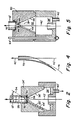
- Fig. 3 is a longitudinal cross section of another embodiment of the invention.
- Fig. 4 is a perspective view illustrating a portion of the apparatus of Fig. 3.
- Fig. 5 is a longitudinal cross section of yet another embodiment of the invention.
- the numeral 10 denotes generally the apparatus of this invention and includes a vertically extending container or tube 12 having an upper flange 14 which may be integral or nonintegral with the container.
- Flange 14 is provided with a fluid inlet line 16 terminating in an annular channel 18, with a second and radially outermost channel 20 communicating with conduit 22.
- 24 denotes a flared conical wall portion of flange 14, the lower portion of which terminates in upper opening 30 of container 12.
- the numeral 32 denotes an opening at the lower portion of container 12.
- a second flange 34, also integral or nonintegral, is provided at the lower end of container 12, flange 34 having an annular flow surface 36 in the general form of an inverted funnel.
- a generally vertically extending slot 44 on surface 36 extends from opening 32 to the lower part of surface 36.
- the structure is workable for limited angles formed between annular surface 36 and the axis of tube or container 12. At large angles, the fluid stream no longer attaches to surface 36. Because surface 36 is axis symmetric (without slot 44), fluid emerging from tube 12 would often be unstable in its location and might fluctuate from one position to another around surface 36. If this oscillation becomes too rapid, the liquid stream will release from surface 36 and become entrained along fiber 42. The presence of slot 44 overcomes this instability and confines the fluid to one region of surface 36, thereby stabilizing and confining the flow of fluid along the slot.
- the lower portion of surface 36 communicates with annular chamber 38 which functions as a liquid collection chamber. Pipe or tube 40 serves as a drain for chamber 38.
- a vertically running glass fiber is schematically denoted as 42, with 42 being coincident with an imaginary vertical axis of the fiber.
- a gas cooling chamber 46 is schematically shown and may assume any conventional form of such devices for cooling a hot glass fiber.
- a fiber coating apparatus 48 is also schematically indicated, with any conventional device of this type being suitable. It will be understood that the details of the gas cooling device 46 and the fiber coating device 48 form no part of this invention.
- FIG. 1 The operation of the apparatus/method shown at Fig. 1 is as follows.
- a hot glass fiber 42 as may be drawn from a glass furnace, is passed vertically through openings 30 and 32 of container 12. It will be observed that there are no obstructions between openings 30 and 32 along the vertical axis.
- Liquid coolant 25 then is fed into the upper portion of the apparatus through conduit 16 and into first annular channel 18 from which it overflows into the region of conical wall 24. Excess liquid spills into outer annular chamber 20 for discharge through conduit 22.
- the vertical extent of liquid 25 between the point which fiber 42 enters the coolant liquid and lower opening 32 remains constant.
- Liquid 25 constantly flows downwardly through container 12 and onto flow surface 36, this surface stream of liquid being denoted as 25'.
- Liquid 25' collects in chamber 38 for discharge from conduit 40.
- Glass fibers are drawn at temperatures as high as 2000 o C.
- the fiber temperature may be about 1700 o C at the time it enters the liquid coolant.
- a vapor barrier or jacket therefore forms about the fiber as it begins to traverse liquid 25.
- the vapor barrier preferably remains around the fiber during its entire traverse through the liquid, since its presence enhances the diversion of the liquid toward slanted flow surface 36. If the fiber were wetted by the liquid, a greater liquid diverting force would be required.
- the length of the liquid column is therefore preferably sufficiently short that the fiber temperature is always sufficiently high to maintain the vapor barrier.
- the column length is preferably long enough to cool the fiber to about that minimum temperature required to maintain the vapor barrier; that temperature is referred to herein as the critical temperature.
- Another factor that determines the column length is the temperature of the fiber as it enters the liquid, which in turn depends on the draw temperature, the draw speed, and the distance between the fiber draw furnace and the liquid cooler column.
- the critical temperatures for three liquid coolants are listed in the following table.
- the minimum heat flux emitted by the glass fiber must be greater than the minimum heat flux required to sustain steady film boiling of the liquid coolant.
- Water is a desirable coolant because of its low cost.
- the fiber temperature must be at least 600 o C. If water contacts the fiber, the fiber temperature will immediately drop from about 600 o C to below 100 o C, the boiling point of water. The resultant thermal shock is sufficient to cause fiber breakage. Therefore, the temperature of the fiber as it exits the water is preferably somewhat above 600 o C.
- gas cooling apparatus 46 To further cool the fiber, so that it does not detrimentally affect the coating material, it is passed through gas cooling apparatus 46. When the fiber enters the coater, it is preferred that the maximum fiber temperature be about the same as the coating material temperature.
- a UV curable urethane acrylate coating material can be supplied to the fiber at 60 o C.
- Refrigerant 113 also known a 1, 1, 2 trichloro 1, 2, 2 trifluoro ethane
- a fiber cooler employing such a coolant would probably not require an additional gas cooler, depending on factors such as the particular coating material employed.
- Fig. 2 of the drawings a modification is illustrated wherein corresponding elements (of the lower portion of the apparatus) are denoted by a prime.
- the significant difference between the construction of Fig. 1 and Fig. 2 is that in the latter the lower end of container 12' carries a plate 50.
- the plate is provided with a centrally disposed passage 52, the latter having a longitudinal axis 54.
- axis 54 makes an acute angle A with vertical axis 42, the latter being coincident with the hot glass fiber.
- Passage 52 is, in this embodiment, the container lower opening.
- An annularly continuous surface 36' again in the general form of a truncated, inverted funnel or cone, meets the lower portion of plate 50 at region 56.
- Passage 52 provides liquid 25' with a momentum that changes the direction of the liquid from the axis of fiber 42 toward slot 44' in surface 36'. The liquid flows as a stabilized stream 25' along and within slot 44'.
- container 12' was a transparent tube about 6 inches long and whose internal diameter was 1/2 inch.
- Plate 50 was 1/8 inch thick and passage 52 of a diameter of 0.177 inches.
- the angle A between passage axis 54 and fiber axis 42' was 30 degrees.
- the cross sectional dimensions of slot 44' were 1/8 inch wide by 1/16 inch deep.
- the use of plate 50 permits dripless starting and stopping, modest flow rates to maintain desired liquid column length and minimum distance between the edge of passage 52 to the glass fiber 42' of about 0.08 inches.
- Fiber velocity was about 7.1 meters per second.
- FIG. 3 of the drawings those elements which are common to the embodiment of Fig. 1 are again denoted by a prime, while those elements which are not common bear different reference numerals.
- Auxiliary passage 17 feeds from 16' to 25'.
- a vertically extending transparent container or tube 12' is provided at its upper portion with a cushion 62, the latter positioned around the lower portion of container upper opening 30'.
- An O-ring 60 is provided around the exterior surface of the upper end of tube 12'.
- a similar cushion and O-ring are located at the bottom end of tube 12'.
- Tube 12' functions in the same manner as container 12 of Fig. 1.
- Any one of a plurality of angularly displaced threaded rods 64 may be employed to space upper flange member 14' from lower flange member 34'.
- a male connector 68 is threaded into an upper portion of member 34', with its lower portion 32' corresponding to lower container opening 32 of Fig. 1.
- a longitudinally slit tube 72 is curved, and has a longitudinal and curved axis 74 as also seen at Fig. 4. The uppermost portion of tube 72 is clamped by connector 68, with the action being such that liquid coolant flows from the upper portion of the apparatus through tube 12', through connector 68 and out of lower container opening 32' within connector 68.
- Tube 72 has an inside diameter of 0.17 inch, and its tangent angle at the bottom end thereof is between about 40 to 45 degrees from the axis of fiber 42'. Tube 72 extended downwardly about 2 inches from connection 68. Various lengths between 3 inches to 12 inches were employed for tube 12'; its inside diameter was 0.75 inch, and its outside diameter was 1 inch. The longer length was preferred since it permits a greater range of liquid path lengths.
- a transparent tube 12' in Fig. 3 permits the height of the liquid level in tube 12' to be regulated.
- the liquid level can be observed visually or it can be measured by optical systems such as liquid level sensors and photodiode arrays.
- the flow rate of liquid into port 16' can be regulated to maintain the liquid level at a predetermined height 27 depending upon the requirements of the system. The requirements may vary with the type of liquid employed and the rate at which the fiber is drawn, which in turn determines the temperature of the fiber as it enters the liquid. If the height 27 of the liquid were initially maintained at a specific level for an initial draw rate, the liquid level height may be increased if the draw rate is increased.
- a system for automatic regulation includes a light source 94, a photodiode array 96, a control circuit 98, a valve 100, and a coolant liquid source 102 governed by the valve.
- These elements for automatic control are of conventional construction and arrangement and hence need not be described in detail.
- Liquid level 27 may be measured continuously or intermittantly.
- FIG. 5 A further embodiment is illustrated in Fig. 5 wherein elements similar to those in Figs. 1 and 3 are representated by primed reference numerals. That portion of the apparatus above tube 12' is not shown since it is identical to that of Fig. 3.
- Lower flange member 80 is provided with a conical cavity 82, the axis 84 of which is offset with respect to fiber 42'. Cavity 82 is defined by annular flow surface 86.
- Cylindrical passage 88 is formed axially within member 80 such that it intersects surface 86 below apex 90 of conical cavity 82.
- Slot 44' is formed along that portion of surface 86 that is intersected by opening 88.
- surface 86 made a 20 degree angle with respect to cone axis 84.
- the height of conical cavity 82 was 3.0 inches.
- the overall height of member 80 was 3.75 inches, and the tube receiving shoulder 92 was 9/16 inch below the upper surface of member 80.
- the diameter of passage 88 was 0.125 inch and the axis of passage 88 was displaced from axis 84 by 0.250 inch.
- the cross sectional dimensions of slot 44' were 1/8 inch wide by 1/16 inch deep.
- the glass fiber travels downwardly.
- the fiber may enter the coolant bath from below and exit from the container upper opening.
- flow surfaces 36, 36', and 86 are shown as curved and of annular form. These surfaces could be flat, such as a single flat wall, and need not be of 360 degrees angular extent (Figs. 1, 2 and 5) or even of 180 degrees angular extent (Fig. 3).
- the upper and lower container openings can be rectangular, as well as circular.
Landscapes
- Engineering & Computer Science (AREA)
- Chemical & Material Sciences (AREA)
- Manufacturing & Machinery (AREA)
- Life Sciences & Earth Sciences (AREA)
- General Life Sciences & Earth Sciences (AREA)
- Geochemistry & Mineralogy (AREA)
- Physics & Mathematics (AREA)
- Thermal Sciences (AREA)
- Materials Engineering (AREA)
- Organic Chemistry (AREA)
- Surface Treatment Of Glass Fibres Or Filaments (AREA)
- Optical Fibers, Optical Fiber Cores, And Optical Fiber Bundles (AREA)
- Manufacture, Treatment Of Glass Fibers (AREA)
Applications Claiming Priority (2)
| Application Number | Priority Date | Filing Date | Title |
|---|---|---|---|
| US529627 | 1990-05-29 | ||
| US07/529,627 US5043001A (en) | 1990-05-29 | 1990-05-29 | Method and apparatus for fiber cooling |
Publications (1)
| Publication Number | Publication Date |
|---|---|
| EP0459032A1 true EP0459032A1 (fr) | 1991-12-04 |
Family
ID=24110681
Family Applications (1)
| Application Number | Title | Priority Date | Filing Date |
|---|---|---|---|
| EP90125487A Withdrawn EP0459032A1 (fr) | 1990-05-29 | 1990-12-24 | Procédé et dispositif pour le refroidissement d'une fibre de verre |
Country Status (5)
| Country | Link |
|---|---|
| US (1) | US5043001A (fr) |
| EP (1) | EP0459032A1 (fr) |
| JP (1) | JPH04228448A (fr) |
| AU (1) | AU7535791A (fr) |
| CA (1) | CA2033721A1 (fr) |
Families Citing this family (15)
| Publication number | Priority date | Publication date | Assignee | Title |
|---|---|---|---|---|
| US5171609A (en) * | 1990-12-04 | 1992-12-15 | Fusion Systems Corp. | Fiber curing with fluid flow |
| JPH05124841A (ja) * | 1991-06-12 | 1993-05-21 | Sumitomo Electric Ind Ltd | ハーメチツクコート光フアイバの製造方法 |
| US5314515A (en) * | 1992-07-14 | 1994-05-24 | Corning Incorporated | Method and apparatus for fiber cooling |
| US5346520A (en) * | 1992-09-23 | 1994-09-13 | Corning Incorporated | Apparatus for applying a carbon coating to optical fibers |
| US5366527A (en) * | 1993-04-05 | 1994-11-22 | Corning Incorporated | Method and apparatus for coating optical waveguide fibers |
| DE19644350A1 (de) * | 1996-10-25 | 1998-04-30 | Alsthom Cge Alcatel | Verfahren und Vorrichtung zum Herstellen einer optischen Glasfaser |
| KR100248066B1 (ko) * | 1998-01-13 | 2000-03-15 | 윤종용 | 광섬유인출장치의냉각기 |
| BR9912235A (pt) * | 1998-07-20 | 2001-04-10 | Corning Inc | Montagem de revestimento de fibra tendo uma matriz de guia arrefecida e método de uso da mesma |
| US6537377B1 (en) | 1999-09-03 | 2003-03-25 | Alcatel | Apparatus for coating optical fibers |
| US6546758B1 (en) | 2000-08-16 | 2003-04-15 | Alcatel | Multi-chamber fiber cooling apparatus |
| US20040194513A1 (en) * | 2003-04-04 | 2004-10-07 | Giacobbe Frederick W | Fiber coolant system including improved gas seals |
| US8230704B2 (en) | 2009-10-28 | 2012-07-31 | Corning Incorporated | Systems and methods for cooling optical fiber |
| TWI509118B (zh) * | 2013-04-26 | 2015-11-21 | Asiatic Fiber Corp | Preparation of conductive yarns |
| US10007077B2 (en) | 2013-09-04 | 2018-06-26 | Bae Systems Information And Electronic Systems Integration Inc. | Direct impingement cooling of fibers |
| CN105859122B (zh) * | 2016-03-31 | 2018-06-26 | 杭州富通通信技术股份有限公司 | 光纤拉丝工艺 |
Citations (4)
| Publication number | Priority date | Publication date | Assignee | Title |
|---|---|---|---|---|
| US4208200A (en) * | 1978-05-08 | 1980-06-17 | Corning Glass Works | Filament coating system |
| US4594088A (en) * | 1985-05-28 | 1986-06-10 | At&T Technologies, Inc. | Method and apparatus for making, coating and cooling lightguide fiber |
| JPS63159239A (ja) * | 1986-12-22 | 1988-07-02 | Sumitomo Electric Ind Ltd | 光フアイバの製造方法 |
| JPS63248742A (ja) * | 1987-04-06 | 1988-10-17 | Sumitomo Electric Ind Ltd | 光フアイバの製造方法 |
Family Cites Families (4)
| Publication number | Priority date | Publication date | Assignee | Title |
|---|---|---|---|---|
| US3620805A (en) * | 1969-03-17 | 1971-11-16 | Carl Martin | Method for the continuous hot galvanizing of continuously formed elements |
| US3977854A (en) * | 1972-06-07 | 1976-08-31 | Owens-Corning Fiberglas Corporation | Apparatus for and method of coating glass fibers |
| US4396409A (en) * | 1981-12-11 | 1983-08-02 | Corning Glass Works | Method of improving fatigue resistance of optical fibers |
| US4583485A (en) * | 1983-06-30 | 1986-04-22 | At&T Technologies, Inc. | Apparatus for coating a lightguide fiber |
-
1990
- 1990-05-29 US US07/529,627 patent/US5043001A/en not_active Expired - Lifetime
- 1990-12-24 EP EP90125487A patent/EP0459032A1/fr not_active Withdrawn
-
1991
- 1991-01-07 CA CA002033721A patent/CA2033721A1/fr not_active Abandoned
- 1991-04-24 AU AU75357/91A patent/AU7535791A/en not_active Abandoned
- 1991-05-29 JP JP3152310A patent/JPH04228448A/ja active Pending
Patent Citations (4)
| Publication number | Priority date | Publication date | Assignee | Title |
|---|---|---|---|---|
| US4208200A (en) * | 1978-05-08 | 1980-06-17 | Corning Glass Works | Filament coating system |
| US4594088A (en) * | 1985-05-28 | 1986-06-10 | At&T Technologies, Inc. | Method and apparatus for making, coating and cooling lightguide fiber |
| JPS63159239A (ja) * | 1986-12-22 | 1988-07-02 | Sumitomo Electric Ind Ltd | 光フアイバの製造方法 |
| JPS63248742A (ja) * | 1987-04-06 | 1988-10-17 | Sumitomo Electric Ind Ltd | 光フアイバの製造方法 |
Non-Patent Citations (2)
| Title |
|---|
| PATENT ABSTRACTS OF JAPAN, vol. 12, no. 433 (C-543)[3280], 15th November 1988; & JP-A-63 159 239 (SUMITOMO ELECTRIC IND. LTD) 02-07-1988 * |
| PATENT ABSTRACTS OF JAPAN, vol. 13, no. 56 (C-566)[3404], 8th February 1989; & JP-A-63 248 742 (SUMITOMO ELECTRIC IND. LTD) 17-10-1988 * |
Also Published As
| Publication number | Publication date |
|---|---|
| JPH04228448A (ja) | 1992-08-18 |
| AU7535791A (en) | 1991-12-05 |
| CA2033721A1 (fr) | 1991-11-30 |
| US5043001A (en) | 1991-08-27 |
Similar Documents
| Publication | Publication Date | Title |
|---|---|---|
| US5043001A (en) | Method and apparatus for fiber cooling | |
| KR0165004B1 (ko) | 광섬유 인발로 및 인발 방법 | |
| CA1289747C (fr) | Technique de fabrication de fibres optiques | |
| US20030202169A1 (en) | Compact, high-efficiency condensation nucleus counter | |
| CA1165075A (fr) | Methode d'enduction de guides d'ondes faits de fibres | |
| EP0079186B1 (fr) | Dispositif pour l'étirage de fibres optiques | |
| JPH0718083B2 (ja) | 繊維の被覆方法およびその装置 | |
| EP1032541B1 (fr) | Procede et appareil permettant de refroidir des fibres optiques | |
| US5100449A (en) | Method of forming glass articles | |
| CA1098318A (fr) | Methode et appareil pour l'etirage de fibres de verre | |
| JPH0655989B2 (ja) | 繊維被覆装置 | |
| JPH027891B2 (fr) | ||
| US4533570A (en) | Method and apparatus for coating optical waveguide fibers | |
| TW202142502A (zh) | 用於製造玻璃帶的方法及設備 | |
| EP0971859B1 (fr) | Ensembles de protection thermique a ailettes pour appareil formant des fibres | |
| EP1101745B1 (fr) | Dispositif et procédé d'étirage de fibres optiques à partir d'une préforme | |
| US4828608A (en) | Process for ultrapurification of indium | |
| JPH11171582A (ja) | 光ファイバ冷却装置 | |
| SE439479B (sv) | Forfarande och apparat for framstellning av glasfibrer | |
| JPH0891862A (ja) | 光ファイバ線引方法および線引炉 | |
| FI114312B (fi) | Menetelmä ja laitteisto optisen kuidun valmistuksessa | |
| CA2508582C (fr) | Systeme de guidage pour lignes de signalisation, dispositif pour mesurer les temperatures et/ou la concentration, et methode d'utilisation | |
| CN110225896B (zh) | 具有减小的润湿长度的光纤涂覆模头 | |
| JP3991399B2 (ja) | 光ファイバの冷却装置及び製造方法 | |
| KR100278147B1 (ko) | 광섬유 진동 방지장치 |
Legal Events
| Date | Code | Title | Description |
|---|---|---|---|
| PUAI | Public reference made under article 153(3) epc to a published international application that has entered the european phase |
Free format text: ORIGINAL CODE: 0009012 |
|
| AK | Designated contracting states |
Kind code of ref document: A1 Designated state(s): DE FR GB IT |
|
| STAA | Information on the status of an ep patent application or granted ep patent |
Free format text: STATUS: THE APPLICATION IS DEEMED TO BE WITHDRAWN |
|
| 18D | Application deemed to be withdrawn |
Effective date: 19920605 |