EP0459329A1 - Dispositif fixe de conteneur - Google Patents
Dispositif fixe de conteneur Download PDFInfo
- Publication number
- EP0459329A1 EP0459329A1 EP91108538A EP91108538A EP0459329A1 EP 0459329 A1 EP0459329 A1 EP 0459329A1 EP 91108538 A EP91108538 A EP 91108538A EP 91108538 A EP91108538 A EP 91108538A EP 0459329 A1 EP0459329 A1 EP 0459329A1
- Authority
- EP
- European Patent Office
- Prior art keywords
- container
- trough
- tub
- stand device
- supports
- Prior art date
- Legal status (The legal status is an assumption and is not a legal conclusion. Google has not performed a legal analysis and makes no representation as to the accuracy of the status listed.)
- Withdrawn
Links
Images

Classifications
-
- B—PERFORMING OPERATIONS; TRANSPORTING
- B65—CONVEYING; PACKING; STORING; HANDLING THIN OR FILAMENTARY MATERIAL
- B65D—CONTAINERS FOR STORAGE OR TRANSPORT OF ARTICLES OR MATERIALS, e.g. BAGS, BARRELS, BOTTLES, BOXES, CANS, CARTONS, CRATES, DRUMS, JARS, TANKS, HOPPERS, FORWARDING CONTAINERS; ACCESSORIES, CLOSURES, OR FITTINGS THEREFOR; PACKAGING ELEMENTS; PACKAGES
- B65D90/00—Component parts, details or accessories for large containers
- B65D90/12—Supports
- B65D90/125—Docking stations, i.e. for the temporary support of the container
-
- B—PERFORMING OPERATIONS; TRANSPORTING
- B65—CONVEYING; PACKING; STORING; HANDLING THIN OR FILAMENTARY MATERIAL
- B65D—CONTAINERS FOR STORAGE OR TRANSPORT OF ARTICLES OR MATERIALS, e.g. BAGS, BARRELS, BOTTLES, BOXES, CANS, CARTONS, CRATES, DRUMS, JARS, TANKS, HOPPERS, FORWARDING CONTAINERS; ACCESSORIES, CLOSURES, OR FITTINGS THEREFOR; PACKAGING ELEMENTS; PACKAGES
- B65D90/00—Component parts, details or accessories for large containers
- B65D90/22—Safety features
- B65D90/24—Spillage-retaining means, e.g. recovery ponds
-
- B—PERFORMING OPERATIONS; TRANSPORTING
- B65—CONVEYING; PACKING; STORING; HANDLING THIN OR FILAMENTARY MATERIAL
- B65F—GATHERING OR REMOVAL OF DOMESTIC OR LIKE REFUSE
- B65F1/00—Refuse receptacles; Accessories therefor
- B65F1/14—Other constructional features; Accessories
- B65F1/141—Supports, racks, stands, posts or the like for holding refuse receptacles
-
- B—PERFORMING OPERATIONS; TRANSPORTING
- B65—CONVEYING; PACKING; STORING; HANDLING THIN OR FILAMENTARY MATERIAL
- B65F—GATHERING OR REMOVAL OF DOMESTIC OR LIKE REFUSE
- B65F1/00—Refuse receptacles; Accessories therefor
- B65F1/14—Other constructional features; Accessories
- B65F1/1426—Housings, cabinets or enclosures for refuse receptacles
Definitions
- the invention relates to a container stand device, in particular for containers for holding metal chips and / or small scrap.
- the swarf generated during metal cutting is contaminated with the drilling oil used in the machining, and often also with lubricating oil.
- the drilling oil and the lubricating oil penetrate through holes in the bottom of the container or other leaks. This is reinforced when the container is installed outdoors by the rainwater falling into the container. The same applies to numerous other waste materials, including fine-grained solids emerging from the container.
- the invention has for its object to avoid environmental damage caused by contaminants escaping from the container.
- this purpose is achieved by a transportable, flat, rectangular trough, the bottom of which is lowered on one or both shorter sides of the rectangle to form recessed trough sections and is supported on its higher section and with support for the container rising within the trough is provided.
- the container is placed on the supports. Liquid escaping from it drips from it and flows on the bottom of the tub into the recessed tub sections, from which it can be removed.
- protrusions protrude from the higher section of the base into the recessed trough sections, and a collecting trough is removably arranged in each of these under the protrusion.
- the liquid can thus be removed in a simple manner, namely by removing and emptying the collecting troughs.
- the collecting troughs can be closed at the top except for a slot through which the liquid dripping at the end edge of the projection reaches them. This makes it easier to handle the collection trays when removing and emptying them; it prevents spillover.
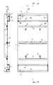
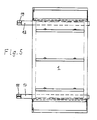
- the bottom 1 of a rectangular tub 2 made of welded sheet steel is lower on two tub sections 3 arranged on the shorter sides of the rectangle than in between; the tub is on the floor with the tub sections 3 and is supported in the middle by a double-T beam 4.
- Three wooden strips 5 are arranged on the tub floor and fastened by screwing to brackets 6 welded to the tub floor.
- the wooden strips 5 run in the transverse direction of the tub 1.
- the middle is above the double-T beam 4, the other two are close to the lower tub sections 3.
- the wooden strips 5 form a support for the container.
- the tub 1 can be gripped on four eyelets 7 in order to receive and deposit it.
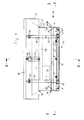
- a collecting trough 8 is inserted in each of the lower trough sections 3.
- a projection 9 protruding from the higher section of the base 2 into the tub section 3 ends above this collecting trough.
- the projection 9 is bent slightly downwards. At its lateral ends, it carries baffles 10 extending obliquely from the tub wall, so that liquid running over the projection 9 cannot drip outside the narrow side walls 11 of the collecting tub 8 (FIGS. 6 and 7).
- the width of the collecting troughs 8 is dimensioned such that the collecting troughs 8 can be pulled out from under the projections 9 within the trough sections 3 and then lifted out. Even with the level meters indicated at 12, the collecting troughs could be closed at the top except for a slot under the projection 9.
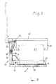
- the tub 1 lies without the double-T support 4 on a foot 13 of a stand frame 14 made of steel construction, which supports a cover 15 for the tub.
- the foot 13 consists of a concrete slab 16 and two double-T profiles 17 enclosing the concrete slab 16 and is arranged between the lower tub sections 3 under the bottom 2 of the tub 1.
- the double-T profiles 17 protrude on one side beyond the concrete slab 16. Here they carry at their ends two supports 19 connected by a beam 18.
- the cover 15 is fastened to the upper ends of the supports 19 in joints 20 and is further held in a joint 22 by a lifting cylinder 21 supported against the beam 18 and can be pivoted from the horizontal position shown into the vertical position.
- the lifting cylinder 21 pivots itself in a protective housing 23. Instead of the lifting cylinder 21, a motorized or manually operated actuator would also be possible.
- An apron 24 made of a plastic film hangs all around on the lid 15 so far that it encloses a container 25 placed on the wooden strips 5 at the top.
- lids are provided on three sides in the form of a flap 26 arranged on the tub rim, which can be folded up at an angle to the container wall and rests against it with an elastic sealing lip 27. Such a flap would be difficult to access on the fourth side facing the supports 19. It is therefore replaced here by a rain protection panel 28 attached to the supports 19.
- the rain protection panel 28, which has the same length as the tub 1 and is therefore the most protruding part of the stand frame 14 in its direction of extension, carries at its end edges in each case two reflectors 29 as orientation aids for a driver approaching for unloading.
- brackets 30 are attached to the supports with inclined end faces 31, on which the lower side edge of a container can slide into the correct position.
- a box indicated at 35 accommodates the hydraulic unit required for the lifting cylinder 21.
Landscapes
- Engineering & Computer Science (AREA)
- Mechanical Engineering (AREA)
- Refuse Receptacles (AREA)
- Packaging Of Machine Parts And Wound Products (AREA)
Applications Claiming Priority (4)
| Application Number | Priority Date | Filing Date | Title |
|---|---|---|---|
| DE9006084U DE9006084U1 (de) | 1990-05-30 | 1990-05-30 | Containerstandvorrichtung |
| DE9006084U | 1990-05-30 | ||
| DE9103622U | 1991-03-23 | ||
| DE9103622U DE9103622U1 (de) | 1990-05-30 | 1991-03-23 | Container-Standvorrichtung |
Publications (1)
| Publication Number | Publication Date |
|---|---|
| EP0459329A1 true EP0459329A1 (fr) | 1991-12-04 |
Family
ID=25956723
Family Applications (1)
| Application Number | Title | Priority Date | Filing Date |
|---|---|---|---|
| EP91108538A Withdrawn EP0459329A1 (fr) | 1990-05-30 | 1991-05-25 | Dispositif fixe de conteneur |
Country Status (2)
| Country | Link |
|---|---|
| EP (1) | EP0459329A1 (fr) |
| DE (1) | DE9103622U1 (fr) |
Cited By (3)
| Publication number | Priority date | Publication date | Assignee | Title |
|---|---|---|---|---|
| EP1316517A1 (fr) * | 2001-12-03 | 2003-06-04 | Lucas G | Abri pour benne de récupération de déchets |
| FR2838146A1 (fr) * | 2002-04-09 | 2003-10-10 | Lucas Sa G | Abri pour conteneur ou benne de recuperation de dechets |
| DE102005053911A1 (de) * | 2005-08-08 | 2007-02-15 | S. Müller Patent Entwicklungs und Verpachtungs GmbH & Co. KG | Verfahren zum Nachrüsten eines Leckageschutzes für stationäre Tanks oder Behälter |
Citations (3)
| Publication number | Priority date | Publication date | Assignee | Title |
|---|---|---|---|---|
| DE3015588C2 (de) * | 1980-04-23 | 1986-04-03 | LGA Gastechnik GmbH, 5480 Remagen | Schutzvorrichtung für Tankbehälter |
| DE3809963A1 (de) * | 1988-03-24 | 1989-10-05 | Friedhelm Quinting | Auffangraum fuer in lagerbehaeltern gelagerte wassergefaehrdende fluessigkeiten sowie verfahren zum herstellen eines auffangraumes |
| EP0428113A1 (fr) * | 1989-11-14 | 1991-05-22 | Jörg Dipl.-Volkswirt Kreuzer | Emplacement pour conteneur |
-
1991
- 1991-03-23 DE DE9103622U patent/DE9103622U1/de not_active Expired - Lifetime
- 1991-05-25 EP EP91108538A patent/EP0459329A1/fr not_active Withdrawn
Patent Citations (3)
| Publication number | Priority date | Publication date | Assignee | Title |
|---|---|---|---|---|
| DE3015588C2 (de) * | 1980-04-23 | 1986-04-03 | LGA Gastechnik GmbH, 5480 Remagen | Schutzvorrichtung für Tankbehälter |
| DE3809963A1 (de) * | 1988-03-24 | 1989-10-05 | Friedhelm Quinting | Auffangraum fuer in lagerbehaeltern gelagerte wassergefaehrdende fluessigkeiten sowie verfahren zum herstellen eines auffangraumes |
| EP0428113A1 (fr) * | 1989-11-14 | 1991-05-22 | Jörg Dipl.-Volkswirt Kreuzer | Emplacement pour conteneur |
Cited By (5)
| Publication number | Priority date | Publication date | Assignee | Title |
|---|---|---|---|---|
| EP1316517A1 (fr) * | 2001-12-03 | 2003-06-04 | Lucas G | Abri pour benne de récupération de déchets |
| FR2832989A1 (fr) * | 2001-12-03 | 2003-06-06 | Lucas Sa G | Abri pour benne de recuperation de dechets |
| FR2838146A1 (fr) * | 2002-04-09 | 2003-10-10 | Lucas Sa G | Abri pour conteneur ou benne de recuperation de dechets |
| EP1354827A1 (fr) * | 2002-04-09 | 2003-10-22 | Lucas G | Abri pour conteneur ou benne de récupération de déchets |
| DE102005053911A1 (de) * | 2005-08-08 | 2007-02-15 | S. Müller Patent Entwicklungs und Verpachtungs GmbH & Co. KG | Verfahren zum Nachrüsten eines Leckageschutzes für stationäre Tanks oder Behälter |
Also Published As
| Publication number | Publication date |
|---|---|
| DE9103622U1 (de) | 1991-09-26 |
Similar Documents
| Publication | Publication Date | Title |
|---|---|---|
| DE9018063U1 (de) | Abstellplatz für Container | |
| DE9103622U1 (de) | Container-Standvorrichtung | |
| DE60035817T2 (de) | Zusammenlegbarer Behälter | |
| DE3020744C2 (de) | Abdeckung für Großbehälter und Becken | |
| DE3934134C2 (de) | Vorrichtung zum Auffangen von Leckflüssigkeit | |
| DE8913716U1 (de) | Auffangwanne für Flüssigkeiten | |
| DE3928031A1 (de) | Palettenartiger korb zur lagerung und zum transport von behaeltern | |
| DE102019123375B3 (de) | Aufbewahrungsbox aus Kunststoff | |
| EP0314958B1 (fr) | Dispositif d'emmagasinage et/ou de transport des liquides polluant l'environnement | |
| EP0272529B1 (fr) | Dispositif de stockage avec volume collecteur de liquides | |
| DE9207315U1 (de) | Vorrichtung zum Trockenlegen von Fahrzeugen | |
| DE9405208U1 (de) | Auffangwanne | |
| DE8535954U1 (de) | Transportables Lager, insbesondere Faßlager für wassergefährdende Flüssigkeiten | |
| EP0400296A1 (fr) | Cellule préfabriquée et transportable en béton armé pour stockage de liquides dangereux | |
| DE3837235A1 (de) | Regenwasser-behaelter | |
| DE9302234U1 (de) | Abfallbehälteranordnung | |
| DE8428582U1 (de) | Container zum aufbewahren und transportieren von abfallstoffen sowie einen rahmen zum transportieren einer anzahl dieser container | |
| DE8207886U1 (de) | Sammeleinrichtung fuer Reste von Motorenoel oder dgl aus Dosen | |
| DE19701715C1 (de) | Aufbewahrungsvorrichtung | |
| DE9413385U1 (de) | Sammeleinrichtung zur Entsorgung von Öl, flüssigen Chemikalien, Lösungsmittel o.dgl. Abfallstoffen | |
| DE9209923U1 (de) | Sammel- und/oder Transportmulde | |
| DE8128503U1 (de) | Verkaufs-oder ausstellungstheke mit kuehlbarem innenraum | |
| CH683356A5 (de) | Schachtkopf mit Verriegelung. | |
| DE4214798A1 (de) | Laboreinrichtung | |
| DE9422253U1 (de) | Lagereinrichtung |
Legal Events
| Date | Code | Title | Description |
|---|---|---|---|
| PUAI | Public reference made under article 153(3) epc to a published international application that has entered the european phase |
Free format text: ORIGINAL CODE: 0009012 |
|
| AK | Designated contracting states |
Kind code of ref document: A1 Designated state(s): BE CH DE ES FR GB IT LI LU NL |
|
| 17P | Request for examination filed |
Effective date: 19920511 |
|
| 17Q | First examination report despatched |
Effective date: 19930309 |
|
| STAA | Information on the status of an ep patent application or granted ep patent |
Free format text: STATUS: THE APPLICATION IS DEEMED TO BE WITHDRAWN |
|
| 18D | Application deemed to be withdrawn |
Effective date: 19940301 |