EP0459435B2 - Procédé pour mesurer la position angulaire d'un moteur à courant continu - Google Patents
Procédé pour mesurer la position angulaire d'un moteur à courant continu Download PDFInfo
- Publication number
- EP0459435B2 EP0459435B2 EP91108768A EP91108768A EP0459435B2 EP 0459435 B2 EP0459435 B2 EP 0459435B2 EP 91108768 A EP91108768 A EP 91108768A EP 91108768 A EP91108768 A EP 91108768A EP 0459435 B2 EP0459435 B2 EP 0459435B2
- Authority
- EP
- European Patent Office
- Prior art keywords
- motor
- change
- signal
- measurement signal
- measuring signal
- Prior art date
- Legal status (The legal status is an assumption and is not a legal conclusion. Google has not performed a legal analysis and makes no representation as to the accuracy of the status listed.)
- Expired - Lifetime
Links
- 238000000034 method Methods 0.000 title claims description 21
- 238000005259 measurement Methods 0.000 claims description 59
- 230000005669 field effect Effects 0.000 claims description 5
- 239000003990 capacitor Substances 0.000 description 4
- 230000000630 rising effect Effects 0.000 description 4
- 238000004804 winding Methods 0.000 description 4
- 238000001514 detection method Methods 0.000 description 3
- 108010076504 Protein Sorting Signals Proteins 0.000 description 1
- 230000006978 adaptation Effects 0.000 description 1
- 230000003044 adaptive effect Effects 0.000 description 1
- 230000003247 decreasing effect Effects 0.000 description 1
- 238000010586 diagram Methods 0.000 description 1
- 230000004069 differentiation Effects 0.000 description 1
- 230000010355 oscillation Effects 0.000 description 1
- 230000007704 transition Effects 0.000 description 1
- 230000001960 triggered effect Effects 0.000 description 1
Images


Classifications
-
- G—PHYSICS
- G01—MEASURING; TESTING
- G01D—MEASURING NOT SPECIALLY ADAPTED FOR A SPECIFIC VARIABLE; ARRANGEMENTS FOR MEASURING TWO OR MORE VARIABLES NOT COVERED IN A SINGLE OTHER SUBCLASS; TARIFF METERING APPARATUS; MEASURING OR TESTING NOT OTHERWISE PROVIDED FOR
- G01D5/00—Mechanical means for transferring the output of a sensing member; Means for converting the output of a sensing member to another variable where the form or nature of the sensing member does not constrain the means for converting; Transducers not specially adapted for a specific variable
- G01D5/12—Mechanical means for transferring the output of a sensing member; Means for converting the output of a sensing member to another variable where the form or nature of the sensing member does not constrain the means for converting; Transducers not specially adapted for a specific variable using electric or magnetic means
- G01D5/244—Mechanical means for transferring the output of a sensing member; Means for converting the output of a sensing member to another variable where the form or nature of the sensing member does not constrain the means for converting; Transducers not specially adapted for a specific variable using electric or magnetic means influencing characteristics of pulses or pulse trains; generating pulses or pulse trains
-
- H—ELECTRICITY
- H02—GENERATION; CONVERSION OR DISTRIBUTION OF ELECTRIC POWER
- H02P—CONTROL OR REGULATION OF ELECTRIC MOTORS, ELECTRIC GENERATORS OR DYNAMO-ELECTRIC CONVERTERS; CONTROLLING TRANSFORMERS, REACTORS OR CHOKE COILS
- H02P7/00—Arrangements for regulating or controlling the speed or torque of electric DC motors
- H02P7/0094—Arrangements for regulating or controlling the speed or torque of electric DC motors wherein the position is detected using the ripple of the current caused by the commutator
Definitions
- the invention relates to a method according to the preamble of the claim 1.
- the adaptation of the difference value and thus the filter to interference signals is special complex.
- This measuring method is particularly complex and often leads still not to the desired correct results.
- the cause is in the Type and quality of the actual measurement signal and the interference signals superimposed on it to see.
- the measurement signal covers a relatively large frequency range from 1 to for example 1000 Hz, it is usually not possible to use all Eliminate interference signals in this way.
- the invention has for its object a method of the aforementioned Art to create that the detection of Extreme values even with measurement signals from 1 to approx. 1000 Hz with superimposed interference signals enables the lower and higher frequency than the measurement signal.
- the higher-frequency interference signals should be in a frequency range that is a multiple of the measurement signal M maximum frequency.
- Such a method is particularly suitable for detecting the rotational position of a DC motor. Since only the tendency of the measurement signal to change is used for this is to output a count pulse, the influence of low and high frequency Interference signals are simply hidden. These include e.g. B. simple Low pass filter, which is in contrast to known measuring methods, such as those from the DD 254254 A1 are known, do not need to be voltage controlled. It is then the intensity and frequency of the interference signal are no longer required to consider.
- Low-frequency interference can also be hidden with little effort because their intensity d. R. is significantly less than that of the measurement signal and is also subject to considerable fluctuations in time. Only the measurement signal has a course for which a tendency to change can be clearly identified and corresponds in principle to that of a sine wave. Since therefore a relative maximum and a relative minimum of the measurement signal can be determined, it can also be the desired counting pulse for the rotational position of the DC motor be won.
- this counting pulse only when the change tendency is reversed in one direction, for example at the transition from the rising to the falling course. In contrast, it means a doubling of the resolution if the counting tendency is won with every reversal of the change becomes. It is thus both when the change tendency is reversed from rising to falling and when the reversal from falling to rising won a count. According to the number of Rotor windings of the DC motor thus result in a resolution that is inversely proportional to this Number is.
- the tendency to change can be determined in a variety of ways. It is particularly simple this in the development of the invention as specified in claim 3. With the help of threshold switching can interference signals, which are superimposed on the measurement signal, without additional aids and, for example can only be filtered out by specifying a suitable threshold. It's just toward it make sure that this threshold is greater than the maximum intensity of the i.d. Usually higher frequency Is interference. This means that these interference signals have no influence on the result of the measurement process.
- the determination of the point in time at which the change in the change in the measurement signal takes place can be carried out in a particularly simple manner using the sample and hold circuit, as specified in claim 4.
- An advantageous embodiment of the basic structure of a switching device suitable for the measuring method can be made using the features as specified in claim 5.
- the field effect transistors are also used to deliver the measurement signal.
- the DC motor can change the duty cycle of the pulse width modulation signal with regard to of the measuring method according to the invention can be ramped up to the desired speed without interference.
- the rotational position can be error-free using the measures can be determined, which are specified in claim 7.
- the part 1 consisting of parts 1a and 1b shows in part 1a the structure of a switching arrangement Control of a DC motor 1 and in part 1b the essential components for processing the Measurement signal for determining the rotational position of the DC motor 1.
- the switching arrangement for driving the DC motor 1 essentially consists of four field effect transistors 2 to 5 and these associated drivers 6 to 9, which in the manner shown with the Motor connections 10 and 11 of the DC motor 1 are connected.
- the drivers 6 and 8 are non-inverting, while drivers 7 and 9 are inverting.
- the right-hand rotation (symbolized with R) or left-hand rotation (L) of the DC motor 1 is activated using switches 12 or 13 set manually or automatically. Here are the starting point in the off State the two switches 12 and 13 open.
- the drivers 6 to 9 are thus connected via a connection 14 ' Ground potential.
- the positive switching transistors 2 and 4 are switched off, the ground switching transistors 3 and 5 switched on via drivers 7 and 9.
- the DC motor 1 is thus short-circuited.
- the associated switch 13 switched on.
- the transistor 4 becomes conductive via the driver 8, while the transistor 3 is still conductive.
- the measurement signal to be evaluated which corresponds to the voltage drop on Corresponds to the drain-source resistance of the field effect transistor 3 and is therefore proportional to the motor current.
- This measurement signal passes through a changeover switch 14 in the signal processing stage, which in part 1b 1.
- the changeover switch 14 is controlled by an RS flip-flop 15, which in turn is connected to the switches 12 and 13 in the manner shown and at its inverting output Q both the changeover switch 14 and a motor rotation direction detection stage (not shown in detail) controls.
- the switch 13 is opened. So that the transistor 5 is additional conductive to transistor 3. The motor 1 is thus short-circuited via the motor connections 11 and 10. At the motor connection 11, the measurement signal continues to be taken.
- Switch 12 is closed to switch on.
- the transistor 2 becomes conductive while transistor 5 is still conductive.
- the measurement signal is now at the motor connection 10 removable, the changeover switch 14 in the position shown and in turn the RS flip-flop 15 controlled to the signal processing stage (Fig. 1b) is forwarded. Again, the movement ends of the DC motor 1, the switch 12 is opened and the motor is short-circuited via the transistors 3 and 5.
- the measurement signal is still at the motor connection while the DC motor 1 is running down 10 removed.
- the measurement signal is first filtered in the signal processing stage (from FIG. 1b) with the aid of a Low pass 20 for eliminating higher-frequency interference and differentiation with the help of a differentiator 21 to eliminate the DC component.
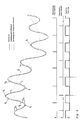
- the measurement signal then has that shown in FIG. 2 Course, wherein an operation of the DC motor at a constant speed is assumed.
- the run of the measurement signal Um is shown in FIG. 2 with an uninterrupted representation.
- Um is a sample and hold circuit, consisting of a switch 22, a capacitor 23 and an EXOR element 24, subjected. There are also subtractors 25, 26, 27 and 28, an adder 29 and threshold switches 30, 31 and 32 and an RS flip-flop 33 are provided, the inverting output of which controls the EXOR element 24.
- the measurement signal Um basically shows the one shown in FIG. 2, drawn with a dotted line Average U an approximately sinusoidal course.
- the mean value has a frequency which is equal to a 1 / nth of the frequency of the measurement signal Um, where n is the number of stator windings.
- the measurement signal Um is used with an adaptive threshold value transmitter checked for its tendency to change.
- This consists of the aforementioned sample and hold circuit (22-24), which is switched on by one of the threshold switches (30-32) formed window discriminator is controlled.
- the threshold switches are with the Subtractor 28 and the adder 29 in connection.
- a constant voltage source 34 supplies one Voltage Uk, e.g. 10% of the amplitude of the measurement signal Um and therefore larger than the maximum occurring Disorder is.
- the voltage Uk is outside the two extreme values of the measurement signal Um the current measurement signal To add (adder 29) or subtracted from it (subtractor 28). Doing so will open a window of width 2 x Uk, which is related to the current measured value Um. Outside the two extreme values means that the measurement signal Um rises or falls monotonously.
- the flip-flop 33 is set and the switch 22 is closed.
- the current Measurement signal Um has a positive tendency to change, i.e. it is always - albeit minor and only due to the time behavior of the capacitor 23 - larger than the dashed signal Uc, the is formed by the capacitor 23. But this is the output signal of the two subtractors 25 and 26 permanently negative (approximately equal to the value Uk), that of the subtractor 27, however, slightly positive.
- the output signal of the subtractor changes 27, since its input signal shifts to slightly negative.
- the downstream threshold switch 32 acts on the EXOR gate 24. This opens the switch 22.
- the maximum value of the Measurement signal in the form of the signal Uc "frozen".
- the input signal of the threshold switch 30 remains continues to be negative, while that of the threshold switch 31 becomes positive as soon as the measurement signal Um is opposite the frozen maximum value now differs as the value Uk.
- the threshold switch 31 thus resets the flip-flop 33.
- the EXOR element 24 thus opens the switch 22 again.
- the input signal of the threshold switch 30 changes as soon as the measurement signal has risen by the value Uk compared to the minimum value.
- the threshold switch 30 is thus set flip-flop 33.
- EXOR gate 24 in turn closes switch 22.
- Reference signal Uc at the capacitor 23 is in turn tracked the measurement signal Um.
- FIG. 1 does not show two additional measures which serve to the rotational position detection according to the invention also at the beginning and at the end of the movement of the direct current motor to use.
- the DC motor starts, these consist of the DC motor Start up with the aid of pulse width modulation, in which the pulse duty factor is changed progressively. Thereby are errors caused by the current peak when switching on and the limit that is usually present the differentiator 21 avoided.
- the DC motor via the second ground-switching field-effect transistor (5 for counterclockwise rotation or 3 short-circuited). This was already described at the beginning of the exemplary embodiment. Of the DC motor then works as a generator and acts as a brake. When evaluating the signal curve it is taken into account that the changes in the measurement signal are now out of phase with the motor operation by 180 ° are. Since at the same time the current direction reverses when braking, the same current edge as in motor operation can be used to obtain the rotary position signal.
- the braking time is then chosen so that the minimum of the measurement signal caused by the current edge at the start of braking, coincides with a current minimum that is generated by the commutator (not shown) of the DC motor coincides.
- the resulting switching signals recognize individually. Specifically, this means that the braking process begins at the beginning of a falling edge of the measurement signal is initiated.
- both during motor operation and when switching the DC motor on and off the switching arrangement shown is used to determine the rotational position from the tendency of the measurement signal to change of the DC motor and thus, for example, the speed.
- the respective DC motors that are connected in the manner according to the invention can be used, for example in motor vehicles as part of a memory circuit, i.e. in positioning devices for targeted Setting of a motor-controlled part or for controlling the individual wiper operation or use the movement of a window regulator.
Landscapes
- Engineering & Computer Science (AREA)
- Power Engineering (AREA)
- Physics & Mathematics (AREA)
- General Physics & Mathematics (AREA)
- Control Of Direct Current Motors (AREA)
- Control Of Motors That Do Not Use Commutators (AREA)
Claims (7)
- Procédé pour détecter des valeurs extrêmes d'un signal de mesure impulsionnel, selon lequel on examine la tendance à la modification du signal de mesure,
caractérisé en ce que
pour déterminer la position angulaire d'un moteur à courant continu, on prend le signal de mesure sur une borne du moteur à courant continu et on émet une impulsion de comptage lors de l'inversion de la tendance à la modification. - Procédé de mesure selon la revendication 1,
caractérisé en ce qu'
une impulsion de comptage (i) est délivrée à chaque inversion de la tendance à se modifier. - Procédé de mesure selon la revendication 1 ou 2,
caractérisé en ce que
la tendance à se modifier est déterminée au moyen d'un interrupteur à valeur de seuil (30 à 32), dans le cas duquel le signal de mesure (Um) est comparé à une valeur de référence (Uc), qui continue à être amenée au signal de mesure jusqu'à ce que la tendance à se modifier s'inverse et qui continue ensuite d'être amenée au signal de mesure lors de l'inversion de la tendance à se modifier en délivrant une impulsion de comptage (i). - Procédé de mesure selon la revendication 3,
caractérisé par
un circuit "d'échantillon et de maintien" (22 à 24), qui déclenche l'impulsion de comptage lors de la tendance à se modifier du signal de mesure à se modifier. - Procédé de mesure selon l'une des revendications 1 à 4,
caractérisé en ce que
la commande du moteur à courant continu (1) a lieu à l'aide de transistors à effet de champ (2 à 5), dont la résistance drain-source est branchée en série avec les raccordements (10, 11) du moteur à courant continu (1). - Procédé de mesure selon l'une des revendications 1 à 5,
caractérisé par
une modulation d'impulsions en largeur avec des impulsions qui augmentent dans le temps en tant que commande de démarrage du moteur à courant continu (1). - Procédé de mesure selon l'une des revendications 1 à 6,
caractérisé en ce que
le débranchement du moteur à courant continu (1) est réalisé en mettant en court-circuit les raccordements du moteur (10, 11) lors de la tendance tombante du signal de mesure (Um).
Applications Claiming Priority (2)
| Application Number | Priority Date | Filing Date | Title |
|---|---|---|---|
| DE4017779 | 1990-06-01 | ||
| DE4017779A DE4017779A1 (de) | 1990-06-01 | 1990-06-01 | Messverfahren fuer die drehlage eines gleichstrommotors |
Publications (4)
| Publication Number | Publication Date |
|---|---|
| EP0459435A2 EP0459435A2 (fr) | 1991-12-04 |
| EP0459435A3 EP0459435A3 (fr) | 1994-10-12 |
| EP0459435B1 EP0459435B1 (fr) | 1995-10-11 |
| EP0459435B2 true EP0459435B2 (fr) | 1999-09-15 |
Family
ID=6407684
Family Applications (1)
| Application Number | Title | Priority Date | Filing Date |
|---|---|---|---|
| EP91108768A Expired - Lifetime EP0459435B2 (fr) | 1990-06-01 | 1991-05-29 | Procédé pour mesurer la position angulaire d'un moteur à courant continu |
Country Status (3)
| Country | Link |
|---|---|
| EP (1) | EP0459435B2 (fr) |
| DE (2) | DE4017779A1 (fr) |
| ES (1) | ES2078383T5 (fr) |
Families Citing this family (9)
| Publication number | Priority date | Publication date | Assignee | Title |
|---|---|---|---|---|
| DE4217265C2 (de) * | 1992-05-25 | 1998-04-09 | El Mos Elektronik In Mos Techn | Verfahren zur Ermittlung von relevanten relativen Extremwerten eines störimpulsbeaufschlagten Signals |
| DE4331742A1 (de) * | 1993-09-20 | 1995-03-23 | Thomson Brandt Gmbh | Schaltung zur Steuerung mit mehreren Sensoren |
| DE19511307C1 (de) * | 1995-03-28 | 1997-01-23 | El Mos Elektronik In Mos Techn | Verfahren und Vorrichtung zur Ermittlung von relevanten relativen Extremwerten eines störbehafteten welligen Gleichstrommotor-Ankerstromsignals mit einer veränderlichen auf die Kommutierung zurückzuführenden Nutzfrequenz und mit davon verschiedenen Störfrequenzen |
| DE19834108C2 (de) * | 1998-07-29 | 2001-06-28 | Sican Gmbh | Verfahren zur Bestimmung der Anzahl von Motorumdrehungen bei Elektromotoren aus Stromripplen |
| US6078154A (en) * | 1999-02-12 | 2000-06-20 | Delco Electronics Corporation | Circuitry for determining actuator position |
| DE10028033A1 (de) | 2000-06-06 | 2001-12-13 | Kostal Leopold Gmbh & Co Kg | Verfahren zum Bereitstellen eines digitalen Stromrippelsignals |
| DE10126169A1 (de) | 2001-05-30 | 2002-12-05 | Kostal Leopold Gmbh & Co Kg | Verfahren zum Bestimmen der Drehstellung der Antriebswelle eines kommutierten Gleichstrommotors |
| US7800321B2 (en) | 2006-09-20 | 2010-09-21 | Behr-Hella Thermocontrol Gmbh | Method for the detection of the rotational position of the rotor of a DC motor with commutator |
| US9859826B2 (en) | 2016-02-03 | 2018-01-02 | Infineon Technologies Ag | Intelligent detection unit (iDU) to detect the position of a rotor controlled by pulse modulation |
Citations (7)
| Publication number | Priority date | Publication date | Assignee | Title |
|---|---|---|---|---|
| DE2606213A1 (de) † | 1975-02-18 | 1976-10-07 | Burroughs Corp | Verfahren und anordnung zum erzeugen von digitalimpulsen mit einer der drehzahl der welle proportionalen frequenz |
| DE3543058A1 (de) † | 1985-12-05 | 1987-06-11 | Teves Gmbh Alfred | Verfahren und schaltungsanordnung zur aufbereitung des ausgangssignals eines drehzahlsensors |
| EP0288119A1 (fr) † | 1987-04-22 | 1988-10-26 | Koninklijke Philips Electronics N.V. | Dispositif de détection des variations d'un signal |
| DE3902166A1 (de) † | 1988-01-25 | 1989-08-03 | Gen Motors Corp | Raddrehzahlfuehler |
| DE3824811A1 (de) † | 1988-07-21 | 1990-01-25 | Teves Gmbh Co Ohg Alfred | Verfahren zur messung der anzahl von umdrehungen eines gleichstrommotors |
| DE3232918C2 (fr) † | 1982-09-04 | 1990-10-04 | Robert Bosch Gmbh, 7000 Stuttgart, De | |
| DE3527906C2 (fr) † | 1985-08-03 | 1991-06-13 | Keiper Recaro Gmbh & Co, 7312 Kirchheim, De |
Family Cites Families (5)
| Publication number | Priority date | Publication date | Assignee | Title |
|---|---|---|---|---|
| DE3307623C2 (de) * | 1983-03-04 | 1986-06-05 | Lenze GmbH & Co KG Aerzen, 3258 Aerzen | Verfahren und Schaltungsanordnung zur Regelung eines Wechselstrom- oder Drehstrommotors |
| EP0251785B1 (fr) * | 1986-07-01 | 1993-08-04 | Conner Peripherals, Inc. | Méthode et appareil pour la commande de moteurs électriques |
| US4794312A (en) * | 1986-09-29 | 1988-12-27 | Hitachi, Ltd. | Method and apparatus for controlling a servo motor |
| DD254254A1 (de) * | 1986-12-01 | 1988-02-17 | Zeiss Jena Veb Carl | Schaltungsanordnung zur erzeugung einer drehzahlproportionalen impulsfolge bei gleichstromkommutatormotoren |
| JPH0833079B2 (ja) * | 1988-01-29 | 1996-03-29 | 三笠産業株式会社 | コンクリートバイブレータ |
-
1990
- 1990-06-01 DE DE4017779A patent/DE4017779A1/de not_active Withdrawn
-
1991
- 1991-05-29 DE DE59106646T patent/DE59106646D1/de not_active Expired - Lifetime
- 1991-05-29 ES ES91108768T patent/ES2078383T5/es not_active Expired - Lifetime
- 1991-05-29 EP EP91108768A patent/EP0459435B2/fr not_active Expired - Lifetime
Patent Citations (7)
| Publication number | Priority date | Publication date | Assignee | Title |
|---|---|---|---|---|
| DE2606213A1 (de) † | 1975-02-18 | 1976-10-07 | Burroughs Corp | Verfahren und anordnung zum erzeugen von digitalimpulsen mit einer der drehzahl der welle proportionalen frequenz |
| DE3232918C2 (fr) † | 1982-09-04 | 1990-10-04 | Robert Bosch Gmbh, 7000 Stuttgart, De | |
| DE3527906C2 (fr) † | 1985-08-03 | 1991-06-13 | Keiper Recaro Gmbh & Co, 7312 Kirchheim, De | |
| DE3543058A1 (de) † | 1985-12-05 | 1987-06-11 | Teves Gmbh Alfred | Verfahren und schaltungsanordnung zur aufbereitung des ausgangssignals eines drehzahlsensors |
| EP0288119A1 (fr) † | 1987-04-22 | 1988-10-26 | Koninklijke Philips Electronics N.V. | Dispositif de détection des variations d'un signal |
| DE3902166A1 (de) † | 1988-01-25 | 1989-08-03 | Gen Motors Corp | Raddrehzahlfuehler |
| DE3824811A1 (de) † | 1988-07-21 | 1990-01-25 | Teves Gmbh Co Ohg Alfred | Verfahren zur messung der anzahl von umdrehungen eines gleichstrommotors |
Also Published As
| Publication number | Publication date |
|---|---|
| EP0459435B1 (fr) | 1995-10-11 |
| EP0459435A3 (fr) | 1994-10-12 |
| ES2078383T3 (es) | 1995-12-16 |
| DE4017779A1 (de) | 1991-12-05 |
| EP0459435A2 (fr) | 1991-12-04 |
| DE59106646D1 (de) | 1995-11-16 |
| ES2078383T5 (es) | 2000-01-16 |
Similar Documents
| Publication | Publication Date | Title |
|---|---|---|
| EP2561608B1 (fr) | Traitement d'une grandeur d'un moteur à courant continu | |
| EP0593933B1 (fr) | Dispositif de détection de mouvement d'une pièce mobile | |
| EP2130293B1 (fr) | Procédé et dispositif de détection de rotation d'un moteur à courant continu à balais | |
| DE10235062B4 (de) | Filterverfahren und A/D-Wandlergerät mit einer Filterfunktion | |
| EP0955522B1 (fr) | Méthode et circuit pour contrôler l'entrefer d'un tachymètre | |
| DE102019132913A1 (de) | Welligkeitzählungs-filterung und verfahren und system zur erkennung von spitzenwerten | |
| DE3934139A1 (de) | Elektronische steuerschaltung fuer einen buerstenlosen gleichstrommotor | |
| EP0412618A2 (fr) | Dispositif de mesure adaptive de vitesse de rotation | |
| DE4444762A1 (de) | Schaltungsanordnung und Verfahren zum Betreiben eines Verstellantriebs | |
| EP0014241B1 (fr) | Procédé pour l'asservissement d'un mécanisme à moteur à courant continu vers un point de destination et un circuit pour la mise en oeuvre de ce procédé | |
| EP0459435B2 (fr) | Procédé pour mesurer la position angulaire d'un moteur à courant continu | |
| DE4308031C2 (de) | Vorrichtung zum Erfassen der Bewegung eines bewegbaren Teils | |
| EP0689054A1 (fr) | Procédé et dispositif pour la mesure du nombre de tours d'un moteur à courant continu avec une commutation mécanique | |
| EP1514342B1 (fr) | Procede et ensemble de circuits pour faire fonctionner des moteurs pas a pas | |
| DE102018216327A1 (de) | Verfahren zum Betreiben einer elektrischen Antriebseinheit, vorzugsweise zum Verstellen eines Bauteils im Kraftfahrzeug, sowie eine Antriebseinheit zum Ausführen des Verfahrens | |
| DE102015106428A1 (de) | Schaltkreis zum Bestimmen einer Position eines Bewegungselements | |
| EP1381148A2 (fr) | Capteur d'angle de rotation à haute résolution pour moteur DC | |
| WO2008064951A1 (fr) | Circuit de détection | |
| EP3544173B1 (fr) | Procédé et dispositif de détermination d'une position d'un rotor dans une machine électrique à commutation électronique | |
| DE102005016893A1 (de) | Schaltungsanordnung und Verfahren zur elektrischen Steuerung und/oder Regelung der Bewegung eines elektrisch betriebenen Aggregats | |
| DE102008026091B4 (de) | Verfahren und Vorrichtung zur Erzeugung eines drehzahlproportionalen Rechtecksignals eines Gleichstrommotors | |
| DE102015106429A1 (de) | Steuervorrichtung für einen Fahrzeugsitz | |
| WO1996038645A1 (fr) | Dispositif de reconnaissance de la force de fermeture d'un moteur electrique de deplacement | |
| DE102010006581A1 (de) | Schaltungsanordnung und Verfahren zur Ermittlung der aktuellen Position eines Rotors eines Elektromotors | |
| DE19653460C2 (de) | Verfahren zur sensorlosen Schritterkennung bei Schrittmotoren |
Legal Events
| Date | Code | Title | Description |
|---|---|---|---|
| PUAI | Public reference made under article 153(3) epc to a published international application that has entered the european phase |
Free format text: ORIGINAL CODE: 0009012 |
|
| AK | Designated contracting states |
Kind code of ref document: A2 Designated state(s): DE ES FR GB IT SE |
|
| PUAL | Search report despatched |
Free format text: ORIGINAL CODE: 0009013 |
|
| AK | Designated contracting states |
Kind code of ref document: A3 Designated state(s): DE ES FR GB IT SE |
|
| 17P | Request for examination filed |
Effective date: 19941025 |
|
| 17Q | First examination report despatched |
Effective date: 19950102 |
|
| GRAA | (expected) grant |
Free format text: ORIGINAL CODE: 0009210 |
|
| AK | Designated contracting states |
Kind code of ref document: B1 Designated state(s): DE ES FR GB IT SE |
|
| ET | Fr: translation filed | ||
| REF | Corresponds to: |
Ref document number: 59106646 Country of ref document: DE Date of ref document: 19951116 |
|
| GBT | Gb: translation of ep patent filed (gb section 77(6)(a)/1977) |
Effective date: 19951115 |
|
| REG | Reference to a national code |
Ref country code: ES Ref legal event code: FG2A Ref document number: 2078383 Country of ref document: ES Kind code of ref document: T3 |
|
| ITF | It: translation for a ep patent filed | ||
| PLBI | Opposition filed |
Free format text: ORIGINAL CODE: 0009260 |
|
| PLBQ | Unpublished change to opponent data |
Free format text: ORIGINAL CODE: EPIDOS OPPO |
|
| PLBF | Reply of patent proprietor to notice(s) of opposition |
Free format text: ORIGINAL CODE: EPIDOS OBSO |
|
| 26 | Opposition filed |
Opponent name: EL-MOS ELEKTRONIK IN MOS TECHNOLOGIE GMBH Effective date: 19960706 |
|
| PLBF | Reply of patent proprietor to notice(s) of opposition |
Free format text: ORIGINAL CODE: EPIDOS OBSO |
|
| PLAW | Interlocutory decision in opposition |
Free format text: ORIGINAL CODE: EPIDOS IDOP |
|
| PLAW | Interlocutory decision in opposition |
Free format text: ORIGINAL CODE: EPIDOS IDOP |
|
| PUAH | Patent maintained in amended form |
Free format text: ORIGINAL CODE: 0009272 |
|
| STAA | Information on the status of an ep patent application or granted ep patent |
Free format text: STATUS: PATENT MAINTAINED AS AMENDED |
|
| 27A | Patent maintained in amended form |
Effective date: 19990915 |
|
| AK | Designated contracting states |
Kind code of ref document: B2 Designated state(s): DE ES FR GB IT SE |
|
| GBTA | Gb: translation of amended ep patent filed (gb section 77(6)(b)/1977) | ||
| ITF | It: translation for a ep patent filed | ||
| ET3 | Fr: translation filed ** decision concerning opposition | ||
| REG | Reference to a national code |
Ref country code: ES Ref legal event code: DC2A Kind code of ref document: T5 Effective date: 19991203 |
|
| REG | Reference to a national code |
Ref country code: GB Ref legal event code: IF02 |
|
| PGFP | Annual fee paid to national office [announced via postgrant information from national office to epo] |
Ref country code: ES Payment date: 20090430 Year of fee payment: 19 |
|
| PGFP | Annual fee paid to national office [announced via postgrant information from national office to epo] |
Ref country code: SE Payment date: 20090512 Year of fee payment: 19 Ref country code: IT Payment date: 20090528 Year of fee payment: 19 Ref country code: FR Payment date: 20090528 Year of fee payment: 19 |
|
| PGFP | Annual fee paid to national office [announced via postgrant information from national office to epo] |
Ref country code: GB Payment date: 20090528 Year of fee payment: 19 |
|
| PLAB | Opposition data, opponent's data or that of the opponent's representative modified |
Free format text: ORIGINAL CODE: 0009299OPPO |
|
| R26 | Opposition filed (corrected) |
Opponent name: EL-MOS ELEKTRONIK IN MOS TECHNOLOGIE GMBH Effective date: 19960706 |
|
| PGFP | Annual fee paid to national office [announced via postgrant information from national office to epo] |
Ref country code: DE Payment date: 20100626 Year of fee payment: 20 |
|
| GBPC | Gb: european patent ceased through non-payment of renewal fee |
Effective date: 20100529 |
|
| EUG | Se: european patent has lapsed | ||
| REG | Reference to a national code |
Ref country code: FR Ref legal event code: ST Effective date: 20110131 |
|
| PG25 | Lapsed in a contracting state [announced via postgrant information from national office to epo] |
Ref country code: SE Free format text: LAPSE BECAUSE OF NON-PAYMENT OF DUE FEES Effective date: 20100530 Ref country code: IT Free format text: LAPSE BECAUSE OF NON-PAYMENT OF DUE FEES Effective date: 20100529 |
|
| REG | Reference to a national code |
Ref country code: DE Ref legal event code: R071 Ref document number: 59106646 Country of ref document: DE |
|
| PG25 | Lapsed in a contracting state [announced via postgrant information from national office to epo] |
Ref country code: FR Free format text: LAPSE BECAUSE OF NON-PAYMENT OF DUE FEES Effective date: 20100531 |
|
| REG | Reference to a national code |
Ref country code: ES Ref legal event code: FD2A Effective date: 20110708 |
|
| PG25 | Lapsed in a contracting state [announced via postgrant information from national office to epo] |
Ref country code: ES Free format text: LAPSE BECAUSE OF NON-PAYMENT OF DUE FEES Effective date: 20110628 Ref country code: GB Free format text: LAPSE BECAUSE OF NON-PAYMENT OF DUE FEES Effective date: 20100529 |
|
| PG25 | Lapsed in a contracting state [announced via postgrant information from national office to epo] |
Ref country code: ES Free format text: LAPSE BECAUSE OF NON-PAYMENT OF DUE FEES Effective date: 20100530 |
|
| PG25 | Lapsed in a contracting state [announced via postgrant information from national office to epo] |
Ref country code: DE Free format text: LAPSE BECAUSE OF EXPIRATION OF PROTECTION Effective date: 20110530 |