EP0459448A2 - Elektrische Verbindereinrichtung - Google Patents
Elektrische Verbindereinrichtung Download PDFInfo
- Publication number
- EP0459448A2 EP0459448A2 EP91108804A EP91108804A EP0459448A2 EP 0459448 A2 EP0459448 A2 EP 0459448A2 EP 91108804 A EP91108804 A EP 91108804A EP 91108804 A EP91108804 A EP 91108804A EP 0459448 A2 EP0459448 A2 EP 0459448A2
- Authority
- EP
- European Patent Office
- Prior art keywords
- lock handle
- connector housing
- arms
- engagement pin
- connector
- Prior art date
- Legal status (The legal status is an assumption and is not a legal conclusion. Google has not performed a legal analysis and makes no representation as to the accuracy of the status listed.)
- Granted
Links
Images





Classifications
-
- H—ELECTRICITY
- H01—ELECTRIC ELEMENTS
- H01R—ELECTRICALLY-CONDUCTIVE CONNECTIONS; STRUCTURAL ASSOCIATIONS OF A PLURALITY OF MUTUALLY-INSULATED ELECTRICAL CONNECTING ELEMENTS; COUPLING DEVICES; CURRENT COLLECTORS
- H01R13/00—Details of coupling devices of the kinds covered by groups H01R12/70 or H01R24/00 - H01R33/00
- H01R13/62—Means for facilitating engagement or disengagement of coupling parts or for holding them in engagement
- H01R13/629—Additional means for facilitating engagement or disengagement of coupling parts, e.g. aligning or guiding means, levers, gas pressure electrical locking indicators, manufacturing tolerances
- H01R13/62933—Comprising exclusively pivoting lever
- H01R13/62938—Pivoting lever comprising own camming means
Definitions
- the present invention generally relates to a connector assembly comprising male and female connectors adapted to be connected together and, more particularly, to a lock mechanism used in the connector assembly to facilitate a connection between the male and female connectors and also to lock one of the male and female connectors in a condition firmly connected with the other of the male and female connectors.
- electric wires used to distribute electric power among numerous electrically operated devices are bound together into harnesses.
- Those electric wires bound together into the harnesses are generally known as wiring harnesses and are generally marked by means of colors for identification purpose.
- the electric wires forming the wiring harness may lead out from an electrically operated device and terminate in a terminal connector for connection with a different electrically operated device through another similar wiring harness having a mating terminal connector at its opposite ends.
- a plug-in connector assembly comprising a plug connector including a number of terminal pins and a socket connector including a corresponding number of terminal sockets for receiving the terminal pins.
- a pushing force must be applied to one of the connectors, while the other of the connectors is held stationary, so that such one of the connectors can be urged to the other of the connectors with the terminal pins inserted into the associated terminal sockets.
- the lever mechanism disclosed in the first mentioned publication comprises a generally tubular operating member comprised of top and bottom walls and a pair of opposite side walls and mounted on one of the plug and socket connectors, for example, the plug connector.
- Each of the side walls of the operating member is formed with a pair of guide grooves cooperable with guide pins formed on each side wall of the socket connector, said guide pins being so defined and so positioned that, when the plug and socket connectors are aligned with each other in readiness for insertion of one of the connectors into the other of the connectors, the guide pins can be received in the associated guide grooves.
- the guide grooves defined in the operating member are so defined and so shaped that, when the operating member is pushed to displace towards a locked position in a direction transverse to the direction of insertion of one of the plug and socket connectors into the other of the plug and socket connectors after the plug and socket connectors are aligned with each other with the guide pins received in the associated guide grooves, the guide pins can be guided deep into the associated guide grooves while the socket connector is forcibly drawn close towards the plug connector and, at the time of completion of the movement of the operating member to the locked position, the plug and socket connectors can be connected together with the terminal pins firmly inserted into the respective terminal sockets.
- each of the guide grooves defined in the operating member is comprised of a straight groove portion extending generally parallel to the direction of insertion of the plug connector into the socket connector and a slant groove portion continued from the straight groove portion and extending generally diagonally relative to the direction of movement of the operating member which is transverse to the direction of insertion.
- the bottom wall of the operating member remains projecting a distance outwardly from a bottom of the connector assembly.
- the top and bottom walls of the operating member movable from the release position towards the locked position must be spaced a distance greater than the thickness of the connector assembly so that the top wall of the operating member spaced a distance outwardly from the top of the connector assembly prior to the movement of the operating member from the release position towards the locked position can be held in contact with the top of the connector assembly after the operating member has been moved to the locked position. Therefore, in the event that an external force acts on the bottom wall of the operating member by some reason, the operating member may be moved from the locked position towards the release position allowing one of the plug and socket connectors to be accidentally separated away from the other of the plug and socket connectors.
- the second mentioned publication that is, the JP Laid-open Patent Publication No. 2-56875, discloses the use of the lever mechanism employed in the form of a generally U-shaped lock handle supported for pivotal movement between release and locked positions spaced angularly from each other about an axis of rotation of the lock handle.
- the generally U-shaped lock handle includes a handle bar and a pair of generally L-shaped arms connected at one ends with opposite ends of the handle bar.
- This U-shaped lock handle is mounted on, for example, the plug connector having its opposite side walls provided with coaxial bearing pins onto which respective free ends of the arms of the lock handle are rotatably mounted.
- the lock handle is pivotable between the release position, in which the arms of the lock handle extend diagonally upwardly in a direction opposite to the socket connector with the handle bar positioned spaced a distance upwardly from a top of the plug connector, and the locked position in which the arms of the lock handle extend generally parallel to the direction of insertion of the plug connector into the socket connector with the handle bar resting on the top of the plug connector.
- the plug connector has its opposite side walls formed with respective recesses for receiving therein associated guide pins formed on corresponding side walls of the socket connector.
- curved cam flanges are formed on the respective free ends of the arms of the lock handle.
- cam flanges are so shaped and so configured that, when the lock handle is pivoted from the release position towards the locked position after the plug and socket connectors have been mated with each other, leading ends of the respective cam flanges with respect to the direction of angular movement of the lock handle towards the locked position enter behind the guide pins so as to encompass the associated guide pins and the continued angular movement of the lock handle can cause the cam flanges to draw the associated guide pins close towards the plug connector so as to enter the respective recesses in the side walls of the plug connector.
- the lever mechanism disclosed in the second mentioned publication also comprises a lock means for locking the lock handle in the locked position, which means comprises a pair of detent projections protruding outwardly from the respective side wall of the plug connector and detent holes defined in the respective arms of the lock handle.
- a lock means for locking the lock handle in the locked position which means comprises a pair of detent projections protruding outwardly from the respective side wall of the plug connector and detent holes defined in the respective arms of the lock handle.
- the present invention is intended to provide an improved connector assembly capable of ensuring a complete and reliable electric connection between first terminal elements in one connector housing and second terminal elements in a mating connector housing when the connector housings are mechanically connected together with an application of a minimized force to a lock handle to rotate the latter from a release position towards a locked position.
- Another object of the present invention is to provide an improved connector assembly of the type referred to above, which does not require any visual inspection to ascertain whether or not the lock handle has been moved to the locked position and, hence, whether or not the first and second terminal elements have been electrically completely connected together.
- a further object of the present invention is to provide an improved connector assembly of the type referred to above, which is effective to avoid any possible separation of any one of arms of a lock handle from its associated bearing pins.
- a still further object of the present invention is to provide an improved connector assembly of the type referred to above, wherein the force required to rotate the lock handle from the release position towards the locked position can be advantageously minimized to facilitate an easy and ready connection of the first and second connector housings.
- a connector assembly which comprises a first connector housing having a plurality of first electric terminal elements; a second connector housing having a corresponding number of second electric terminal elements adapted to be electrically connected with the first electric terminal elements when the first and second connector housings are connected together; a pair of engagement pin members mounted on the first connector housing so as to protrude outwardly therefrom and positioned on respective sides of the first connector housing; and a lock handle having a pair of spaced apart arms and a handle bar connected at opposite ends with the arms.
- the lock handle also has an axis of rotation thereof substantially perpendicular to each of the arms and is angularly displaceably mounted on the second connector housing with the arms positioned on respective sides thereof for rotation between a release position, in which the first and second connector housings are separated from each other, and a locked position in which the first and second connector housings are connected together with the first terminal elements electrically completely connected with the second terminal elements.
- the connector assembly also comprises a shaped cam means defined in a free end portion of each of the arms and cooperable with the corresponding engagement pin member, said shaped cam means being of a generally arcuate shape having a center of curvature which is located offset from the axis of rotation of the lock handle whereby, as the lock handle is rotated from the release position towards the locked position after the first and second connector housings have been aligned with each other, the corresponding engagement pin member is guided along the shaped cam means allowing the first connector housing to be drawn relative to and close towards the second connector housing thereby to accomplish a complete electric connection between the first and second terminal elements upon arrival of the lock handle at the locked position.
- Each of the engagement pin members has a friction-reducing element to facilitate a relative movement of the respective engagement pin member along the shaped cam means during the rotation of the lock handle between the release and locked positions.
- the shaped cam means comprises a generally arcuate guide slot or groove defined in the free end portion of each of the arms of the lock handle and having leading and trailing ends with respect to the direction of rotation of the lock handle from the release position towards the locked position.
- This arcuate guide slot or groove is delimited by long and short cam edges opposite to and spaced a predetermined distance from each other and between the leading and trailing ends.
- an area of the free end of each arm adjacent the leading end of the arcuate guide slot or groove has a straight guide slot or groove defined therein for receipt of and guiding the associated engagement pin member into the leading end of the arcuate guide slot when the first and second connector housings are brought into abutment with each other while the lock handle is held in the release position.
- each of the engagement pin members comprises a shank portion connected at one end to the first connector housing and the opposite end formed with a radially outwardly extending head and wherein the friction-reducing element comprises a generally tubular member rotatably mounted on the shank of the respective engagement pin member.
- the connector assembly may further comprising a detecting means for detecting a complete arrival of the lock handle to the locked position and for providing an indication that, consequent upon the complete arrival of the lock handle at the locked position, the first and second terminal members are electrically completely connected together.
- the arcuate guide groove may be of a generally T-shaped cross-sectional shape and wherein each of the engagement pin members comprises a shank portion connected at one end to the first connector housing and the opposite end formed with a radially outwardly extending head so as to represent a generally T-shaped configuration complemental to the cross-sectional shape of the arcuate guide groove.
- the connector assembly may have a temporary retaining means for retaining the lock handle at the release position thereby to avoid an arbitrary motion of the lock handle about the axis of rotation thereof.
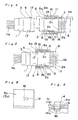
- a harness connector assembly shown therein generally comprises a plug connector and a mating socket connector adapted to be connected with the plug connector to complete the connector assembly.
- the plug connector includes a plug connector housing 1 of generally rectangular cubic configuration accommodating therein a plurality of plug terminals arranged in a predetermined pattern while the socket connector includes a connector includes a socket connector housing 2 of a configuration substantially similar to that of the plug connector housing 1 and accommodating therein a corresponding number of socket terminals arranged in a pattern similar to that of the plug terminals in the plug connector housing 1, said socket terminals being adapted to receive therein the corresponding plug terminals when and after the plug connector has been inserted into the socket connector housing 2 in a manner as will be described later.
- the plug connector housing 1 includes a top wall 1a, a bottom wall 1b, a pair of side walls 1c and 1d and an end wall 1e, all assembled together to render the plug connector housing 1 to assume a generally rectangular box-like configuration.
- the plug connector housing 1 accommodates therein the plug terminals to which harness wires, generally identified by Ha, are soldered or otherwise connected in any known manner so as to extend outwardly from the plug connector housing 1 through perforations defined in the end wall 1e.
- top, bottom and side wall portions of the plug connector housing 2 adjacent the opening thereof and opposite to the end wall 1e form a generally rectangular-sectioned hood which is generally identified by 3 and which is so oversized that the hood 3 can encircle a mating end portion of the socket connector as will be described later.
- the hood 3 is an integral part of the plug connector housing 1, the hood 3 is to be understood as comprised of parts of the top, bottom, side walls 1a to 1e of the plug connector housing for the purpose of the description of the preferred embodiments of the present invention.
- the plug connector housing 1 has a pair of engagement pins 4 rigidly mounted on, or otherwise integrally formed with, respective parts of the side walls 1c and 1d forming the hood 3 so as to protrude laterally outwardly therefrom in coaxial relationship with each other.
- the socket connector housing 2 includes a top wall 2a, a bottom wall 2b, a pair of inner side walls 2c and 2d and an end wall 2e, all assembled together to render the socket connector housing 2 to assume a generally rectangular box-like configuration substantially similar to that of the plug connector housing, but undersized relative thereto so that a front end portion thereof opposite to the bottom wall 2e can be received within the hood 3 in the plug connector housing 1.
- the socket connector housing 2 accommodates therein the socket terminals to which harness wires, generally identified by Hb, are soldered or otherwise connected in any known manner so as to extend outwardly from the socket connector housing 2 through perforations defined in the end wall 2e.
- the socket connector housing 2 also includes a pair of outer side walls 5a and 5b of generally rectangular shape similar to the shape of the associated side wall 2c or 2d of the socket connector housing 2.
- Each of the outer side walls 5a and 5b is secured to, or otherwise integrally formed with, one end of the associated side wall 2c or 2d of the socket connector housing 2, adjacent the bottom wall 2e, in a substantially cantilever fashion so as to be positioned spaced a distance from the associated side wall 2c or 2d while defining a respective bearing chamber 6 between it and the associated side wall 2c or 2d.
- the outer side walls 5a and 5b have respective bearing holes 12 defined therein so that the bearing holes 12 in the respective outer side walls can coaxially align with each other.
- a lock handle is generally identified by 7 and includes, as best shown in Fig. 3, a pair of arms 8a and 8b of identical shape and a handle bar 9 having opposite ends connected or integrally formed with the arms 8a and 8b so as to render the lock handle 7 to represent a generally U-shaped configuration.
- a free end portion of each of the arms 8a and 8b opposite to the handle bar 9 is generally outwardly bulged and includes a bearing pin 11 formed therewith so as to extend laterally outwardly therefrom so that the bearing pins 11 on the respective arms 8a and 8b can coaxially align with each other.
- a generally guide slot 10 of a specific configuration as will be discussed later is defined in the bulged free end portion of each of the arms 8a and 8b.
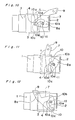
- This lock handle 7 is pivotally mounted on the socket connector housing 2 with the bearing pins 11 engaged relatively rotatably in the bearing holes 12 that are defined in the outer side walls 5a and 5b such that the lock handle 7 can be pivotable about the bearing pins 11 between a release position, as shown in Figs. 6 and 10, and a locked position as shown in Fig. 12.
- the mounting of the lock handle 7 on the socket connector housing 2 can be accomplished by inserting the bulged free end portions of the respective arms 8a and 8b into the bearing chambers 6, expanding the outer side walls 5a and 5b in a direction away from the adjacent inner side walls 2c and 2d of the socket connector housing 2 against their own resiliency so as, to permit the associated bearing pins 11 on the bulged free end portions of the arms 8a and 8b to pass onto the respective bearing holes 12 and finally allowing the outer side walls 5a and 5b to snap into their original positions with the bearing holes 12 receiving therein the respective bearing pins 11 as best shown in Figs. 4 and 5.
- the respective guide groove 10 has leading and trailing ends 10a and 10b, opposite to each other with respect to the direction of pivotal movement of the lock handle 7 from the release position towards the locked position and extends angularly in an offset relationship with the adjacent bearing pin 11, and is delimited between long and short cam edges 10d and 10e confronting with each other.
- the guide slot 10 also has a longitudinal axis 10' extending intermediate of the width B thereof which is substantially uniform over the entire length thereof. The guide slot 10 is so defined and so positioned in the bulged free end portion of the arm 8a that the distance, indicated by L in Fig.
- the plug and socket connector housings 1 and 2 are aligned with each other substantially as shown in Fig. 4 and one of them, for example, the plug connector housing 1, is moved relative to and close towards the socket connector housing 2 until that end portion of the socket connector housing 2 opposite to the bottom wall 2e is loosely received within the hood 3 in the plug connector housing 1 substantially as shown in Fig. 5.
- each of the guide slots 10 is so shaped and so configured that, during the pivotal movement of the lock handle 7 from the release position towards the locked position, the plug connector housing 1 can be forcibly drawn close towards the socket connector housing 2 in cooperation with the associated engagement pin 4.
- a reverse angular movement of the lock handle 7 from the locked position towards the release position allows the plug and socket connector housings 1 and 2 to be separated from each other.
- the short cam edges 10e of the guide slots 10 progressively push the engagement pins 4 so as to cause the plug connector housing 1 to separate from the socket connector housing 2 during the pivotal movement of the lock handle 7 from the locked position towards the release position and, therefore, after the lock handle 7 has been moved to the released position, the plug and socket connector housings 1 and 2 can easily be separated completely from each other manually.
- the plug-in connector assembly including the lock mechanism, of the construction so far shown and described may be of a construction disclosed and claimed in a Japanese Laid-open Utility Model Publication No. 3-4672, published January 17, 1991, the invention of which was invented by Nori Inoue and has been assigned to the same assignee of the present invention.
- Each of the engagement pins 4 which may be either integral or rigid with the respective side walls 1c and 1d of the plug connector housing 1 may be of a generally cylindrical shape. However, the use of the cylindrical engagement pins 4 may possibly bring about a problem which will now be discussed with reference to Fig. 30 showing only one of the engagement pins 4, which is secured to or formed integrally with the side wall 1d of the plug connector housing 1, and its associated guide groove 10.
- the lock handle 7 may possibly occur that the bulged end portion of one or both of the arms 8a and 8b floats relative to the associated side wall 1d with the engagement pin 4 disengaged from the associated guide slot 10 and the lock handle 7 may eventually fail to draw the plug connector 1 close to the socket connector housing 2.
- each of the engagement pins 4 is employed in the form of a pin having a free end formed with a head 4b of a diameter D greater than the diameter of a shank portion of the engagement pin 4 as best shown in Fig. 29.
- each of the engagement pins 4 employed in the plug connector housing 1 is rotatably supported by the associated side wall 1c or 1d in accordance, with the present invention.
- any suitable mounting method may be employed in the practice of the present invention, however, the employment of a mounting method shown in any one of Figs. 9 and 13 to 15 is preferred, reference to which will now be made thereto for the discussion of the mounting method for rotatably securing any one of the engagement pins 4 to the associated side wall 1c or 1d.
- the engagement pin 4 is of a generally cylindrical shape having an annular collar 4a formed integrally therewith so as to protrude radially outwardly from a substantially intermediate portion thereof and also having an annular groove 4b defined therein at a location adjacent one end thereof.
- the side wall 1c or 1d of the plug connector housing 1 has a corresponding bearing hole 14 of generally cylindrical configuration including a larger diameter portion and a reduced diameter portion.
- the engagement pin 4 In order to mount the engagement pin 4 rotatably in the corresponding bearing hole 14, the engagement pin 4 is inserted into the bearing hole 14 so that the annular groove 4b in the engagement pin 4 can protrude a slight distance into a space within the hood 3 while the annular collar 4a is received within the larger diameter portion of the bearing hole 14, and thereafter, a split washer 14a is snapped into the annular groove 4b to avoid any possible separation of the engagement pin 4 from the bearing hole 14.
- the engagement pin 4 of generally cylindrical shape is in the form having, in addition to the annular collar 4a shown in Fig. 9, an anchoring flange 4c formed integrally with one end thereof so as to protrude radially outwardly therefrom.
- This engagement pin 4 is mounted on, specifically in-molded in, the side wall 1c or 1d by the use of any known insert-molding technique.
- the engagement pin 4 may be made of a material, for example, metal, which is dissimilar to the material for the plug connector housing 1.
- At least one end portion of the engagement pin 4 including the collar 4a and the anchoring flange 4c may be applied with an oily substance such as grease or wax before, in a mold designed to form the plug connector housing 1, a melt phase of plastics is injected into the mold.
- an oily substance such as grease or wax
- the engagement pin 4 comprises a post 4d formed integrally with the side wall 1c or 1d by the use of any known plastics molding technique so as to have an anchoring head 4d radially outwardly protruding from a free end thereof, and a flat ring member 4f rotatably mounted on the post 4d and retained in position between the side wall 1c or 1d and the anchoring head 4d.
- the flat ring member 4f contacts any one of the long and short cam edges 10d and 10e.
- the two engagement pins 4 are employed one for each side wall 1c and 1d of the plug connector housing 1.
- those engagement pins 4 may be constituted by respective opposite ends 13a and 13b of a single shaft member 13 as shown in Fig. 15.
- This shaft member 13 has a generally intermediate portion thereof formed with a radially inwardly extending engagement groove 13a and is rotatably inserted in a bearing hole defined in the plug connector housing 1.
- the shaft member 13 so inserted in the bearing hole in the plug connector housing 1 is retained in position by means of a generally elongated elastic stop 27 provided in the plug connector housing 1 and engaged loosely in the engagement groove 13a as shown in Fig. 15. With the elastic stop 13d engaged in the engagement groove 13d in the shaft member 13, the latter will not displace axially within the bearing hole in the plug connector housing 1 and will not separate away from the plug connector housing 1.
- respective parts of at least the side walls 1c and 1d of the plug connector housing 1 defining the hood 3 are exteriorly narrowed at 17 so as to have a reduced width smaller than the width X as measured from an outer surface of one side wall 1c to an outer surface of the other side wall 1d.
- the arms 8a and 8b of the lock handle 7 are of a shape twisted or molded to have a reduced span Y as measured between an inner surface of a front part of the bulged end portion of one arm 8a which confronts the plug connector housing 1 and an inner surface of a front part of the bulged end portion of the other arm 8b, which also confronts the plug connector housing 1, such that, when viewed from bottom as shown in Fig. 4, the span between the bulged end portions of the respective arms 8a and 8b of the lock handle can progressively reduce from a maximum span Z towards the reduced span Y.
- the reduced span Y between the front parts of the bulged end portions of the respective arms 8a and 8b is chosen to be smaller than the width X of the plug connector housing 1 which is in turn chosen to be equal to or smaller than the maximum span Z between respective rear parts of the bulged end portions of the arms 8a and 8b which are opposite to those front parts thereof.
- each of the arms 8a and 8b of the lock handle 7 is formed with a respective engagement projection 15 situated generally intermediate between the associated straight guide groove 10c and the associated bearing pin 11 as shown in Figs. 3, 6 and 7.
- This engagement projection 15 is cooperable with a stopper projection 16 formed on each of the inner side walls 2c and 2d of the socket connector housing 2 as shown in Fig. 8.
- the engagement projections 15 and the stopper projections 16 are so positioned and so configured that, when and so long as the lock handle 7 is held at the release position, the lock handle 7 can assume such a position as best shown in Fig. 10 with the straight guide grooves 10c aligned with the associated engagement pins 4 on the plug connector housing 1 with respect to the direction of insertion of one of the plug and socket connector housings 1 and 2 relative to and towards the other of the plug and socket connector housings 1 and 2 and that, when and after that end portion of the socket connector housing 2 is inserted into the hood 3 of the plug socket connector housing 1, as shown in Figs.
- the arms 8a and 8b of the lock handle 7 are operatively housed within the associated bearing chambers 6 each defined between the inner and outer side walls 2c and 5a, 2d and 5b.
- the outer side walls 5a and 5b of the socket connector housing 2 essentially serve as protective coverings and, accordingly, no external force tending to move the lock handle 7 and/or to separate at least one bearing pin 11 away from the associated bearing hole 12 act on one or both of the arms 8a and 8b of the lock handle 7.
- the temporary retaining means of the construction described above need not be always necessary in the practice of the present invention and may be dispensed with if desired.
- the stopper projections 16 shown and described as formed on the respective side walls 2c and 2d may be respective parts of design indentations formed thereon, or the use of a single combination of one engagement projection 15 and a corresponding stopper projection 16 may suffice in the practice of the present invention.
- housings identified respectively by 1 and 2 have been referred to as the plug and socket connector housings, respectively, the housings 1 and 2 may be used as the socket and plug connector housings, respectively, in which case the lock handle 7 and their associated parts may be provided on either the plug connector housing or the socket connector housing.
- the plug-in connector assembly is provided with a detecting system for detecting whether or not the lock handle has been moved completely to the locked position thereby to provide an indication that the plug terminals in the plug connector have been electrically connected with the socket terminals in the socket connector.
- the plug connector housing 1 is shown to have the engagement pins 4 formed on the respective side walls 1c and 1d while the socket connector housing 2 is shown to have the lock handle 7 operatively carried thereby with the arms 8a and 8b rotatably mounted on the respective bearing pins 11.
- each of the plug and socket connector housings 1 and 2 shown therein is different from that shown particularly in Fig. 1, the plug and socket connector housings 1 and 2 used in the second preferred embodiment of the present invention are substantially similar to those shown in Fig. 1 except that the bearing pins 11 used in the second preferred embodiment of the present invention are secured rigidly to, or otherwise integrally formed with, the respective side walls 2c and 2d of the socket connector housing 2 and that, instead of the straight guide groove 10c defined in the bulged end portion of each of the arms 8a and 8b in the foregoing embodiment of the present invention, a straight guide slot 10f is employed in communication with the associated curved guide slot 10 as best shown in Fig. 9.
- the socket connector housing 2 shown in Figs. 16 and 17 is specifically designed for rigid mounting on an electrically operated device and, for this purpose, instead of the wire harness Hb shown in Fig. 1, it employs a plurality of terminal pins Hc protruding outwardly from the bottom wall of the socket connector housing 2 for electric connection with corresponding electric wires in the electrically operated device by means of soldering.
- the plug and socket connectors are connected together in a manner substantially similar to that shown and described in connection with the foregoing embodiment of the present invention.
- the socket connector housing 2 is rigidly mounted on a casing for the electrically operated device with its opening oriented upwards as shown therein
- the straight guide slots 10f leading into the curved guide slots 10a in the bulged end portions of the respective arms 8a and 8b are oriented upwards when and so long as the lock handle 7 is held in the release position as shown in Fig. 21(a).
- the engagement pins 4 are immediately received within the straight guide slots 10f as shown in Fig. 21(b) in readiness for entry into the associated curved guide slots 10.
- the curved guide slot 10 defined in each bulged end portion is, as best shown in Fig. 19, so curved as to have its center of curvature located laterally offset from the axis 11' of rotation of the lock handle 7 such that the distance between the axis 11' of rotation of the lock handle 7 and the leading end 10a of the respective curved guide slot 10 is greater than that between the axis 11' of rotation and the trailing end 10b of the respective curved guide slot 10.
- the curved guide slot 10 shown in Fig. 19 differs from that shown in Fig.
- leading end 10b is oversized relative to an outer diameter of the corresponding engagement pin 4 to facilitate receipt of such corresponding engagement pin 4 in the leading end 10a of the guide slot 10 through the straight guide slot 10f and that the trailing end 10b thereof extends straight over a slight distance so as to provide a play to the lock handle 7 moved to the locked position.
- the curved guide slot 10 in the bulged end portion of each of the arms 8a and 8b is so shaped and so configured that the leading end 10a angularly extends an angle a, which may correspond to about 15 degrees of rotation of the lock handle 7 about the axis 11' of rotation thereof; the trailing end 10b extends straight over an angle c which may correspond to about 20 degrees of rotation of the lock handle 7 about the axis 11' of rotation thereof; and a portion of the curved guide slot 10 intermediate between the leading and trailing ends 10a and 10b angularly extends an angle b which may correspond to about 110 degrees of rotation of the lock handle 7 about the axis 11' of rotation thereof.
- each of the straight guide slot 10f continued to the leading end 10a of the associated curved guide slot 10 has a width greater than the outer diameter of the corresponding engagement pin 4, the engagement pins 4 can readily be received into the leading ends 10a through the associated straight guide slots 10f.
- the lock handle 7 is pivoted about the axis 11' in a direction shown by the arrow A from the release position towards the locked position.
- the engagement pins 4 make an idle movement relative to the lock handle 7 being rotated without the plug connector housing 1 being positively drawn close towards the socket connector housing 2, because the width of each of the leading ends 10a is greater than the outer diameter of the corresponding engagement pin 4 as hereinabove described.
- the lock handle 7 pivots the angle c of about 20 degrees by the effect of an inertia force further towards the locked position with the engagement pins 4 relatively moving within the straight trailing ends 10b until the lock handle 7 assumes the locked position as shown in Fig. 21(d).
- the lock handle 7 is made of electroconductive material and is formed integrally with elastic contact tongues 20a and 20b extending from the corresponding bulged end portions of the respective arms 8a and 8b in a direction towards the handle bar 9 in a generally parallel relationship with the adjacent arms 8a and 8b.
- Each of the contact tongues 20a and 20b has a free end opposite to the bulged end portion of the associated arm 8a or 8b which is, as best shown in Figs. 18 and 19, substantially curled about the longitudinal axis thereof to define a generally convex contact element 21a or 21b such that a convex contact surface of one contact element 21a and that of the other contact element 21b confront with each other.
- each of these terminal members 22a and 22b has one end formed into a contact element 23a and 23b and the opposite end electrically connected with a connection detector D by means of a respective lead line Wa or Wb.
- terminal members 22a and 22b are so secured to and so positioned in the respective side walls 2c and 2d (the side wall 2d being not shown in Figs. 16 to 21, except for Fig. 18) of the plug connector housing 1 made of electrically insulating material that, when the lock handle 7 has been completely pivoted to the locked position, the contact elements 21a and 21b of the contact tongues 20a and 20b can be electrically connected with the contact elements 23a and 23b of the terminal members 22a and 22b, respectively, in a manner as will be described in detail.
- the side walls 1c and 1d of the plug connector housing 1 have respective detent projections 24 formed therein at a position aligned with the path of angular movement of the corresponding contact element 21a or 21b of the contact tongue 20a or 2b so that, as the lock handle 7 being pivoted approaches the locked position, the contact elements 21a and 21b can slide over the corresponding detent projections 24, as shown by the phantom lines in Fig. 18, while causing the contact tongues 20a and 20b to deform against their own resiliency, and subsequently fall into contact with the associated contact elements 23a and 23b of the terminal members 22a and 22b having slid down the projections 24 as shown by the solid lines in Fig. 18.
- the detent projections 24 serve to inhibit a reverse movement of the lock handle 7 from the locked position back towards the release position in engagement with the contact elements 21a and 21b of the contact tongues 20a and 20b, thereby to keep the lock handle 7 locked in the locked position once it has been angularly moved thereto. This is possible because, once the lock handle 7 has been moved completely to the locked position as described hereinbefore, the projections 24 occupy respective positions trapped within respective detent spaces defined between the arms 8a and 8b and the contact tongues 10a and 20b.
- an electric circuit extending from the terminal member 22a to the other terminal member 22b via the lock handle 7 is a series circuit and, accordingly, the connection detector D may be of a type including a series-connected circuit of an electric power source, for example, a battery, and an indicator such as, for example, a light emitting diode and/or a potentiometer.
- the detector D may include a signal generator for generating, when the lock handle 7 has been moved completely to the locked position with the contact elements 21a and 21b engaged respectively with the contact elements 23a and 23b, an output which may be utilized in any suitable manner, for example, in a computer-assisted assembling machine in an automatic connector production line.
- the connection detector D may be disconnected from the circuit including the terminal members 22a and 22b, once the complete connection between the plug and socket terminals have been confirmed in reference to the indication provided by the connection detector D.
- FIG. 22 A relationship between the angle of rotation of the lock handle 7 and the external force applied to the lock handle 7 to rotate the latter, that is, a load w applied to the arms 8a and 8b, in the second preferred embodiment of the present invention is shown in Fig. 22.
- a load w applied to the arms 8a and 8b in the second preferred embodiment of the present invention is shown in Fig. 22.
- the external force applied to the lock handle 7 to rotate the latter is required to be increased as shown by a spike S.
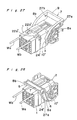
- Figs. 23 to 25 and Figs. 26 to 28 illustrate different application of the concept of the present invention to the plug-in connector assembly comprising the plug and socket connector housings of generally cubic configuration.
- the terminal members having the respective contact elements 23a and 23b are carried by the opposite side walls 1c and 1d of the plug connector housing 1 at specific locations as will be described later.
- the lock handle 7 employed in the embodiment of Figs. 23 to 25 is of a type having the arms 8a and 8b each being curved in an offset relationship to the axis of rotation of the lock handle 7 and formed integrally with a generally elongated elastic contact tongues 24a or 24b protruding from the bulged end portion of the corresponding arm 8a or 8b in a direction close towards the handle bar 9 while defining a detent space 25a or 25b between it and the adjacent arm 8a or 8b.
- the contact tongues 24a and 24b have their respective free ends serving as respective contact areas 26a and 26b adapted to be electrically connected with the contact elements 23a and 23b on the plug connector housing 1 as shown in Fig. 25.
- Detent projections 24' engageable into the detent spaces 25a and 25b, respectively, for locking the lock handle 7 in the locked position once the latter has been moved thereto are formed on the respective side walls 1c and 1d of the plug connector housing 1 so as to protrude laterally outwardly.
- the lock handle 7 shown therein is substantially similar to that shown in Figs. 23 to 25 except that no elastic contact tongue is employed and, hence, no detent space is defined. Instead, detent perforations 27a and 27b cooperable with the detent projections 24' on the plug connector housing 1 are employed and are defined in respective end portions of the arms 8a and 8b adjacent the handle bar 9 of the lock handle 7 as best shown in Figs. 26 and 27 and, also, the handle bar 9 has spaced apart contact areas 9a and 9b defined therein. Those contact areas 9a and 9b of the handle bar 9 are, when the lock handle 7 is moved to the locked position as shown in Fig. 28, brought into contact with spring contacts 22a' and 22b' mounted on the top wall 1a of the plug connector housing 1 and connected with the respective lead lines Wa and Wb as best shown in Figs. 26 and 27.
- the lock handle 7 has been described as made of electroconductive material.
- the use of the electroconductive material for the lock handle 7 may not be always essential and the lock handle 7 may be made of synthetic resin.
- the lock handle 7 is made of synthetic resin, that is, an electrically insulating material, a generally elongated conductor such as, for example, a printed circuit element or a metal strip, may be embedded in the lock handle 7 to provide a circuit element necessary to shortcircuit between the contact elements 23a and 23b upon arrival of the lock handle 7 at the locked position, while opposite ends of the elongated conductor embedded in the lock handle 7 should be exposed bare for engagement with the associated contact elements 23a and 23b.
- the guide path along which any one of the engagement pins 4 moves relative to the associated arm 8a or 8b during the rotation of the lock handle 7 has been shown and described as employed in the form of the curved guide slot 10 which opens completely across the thickness of the bulged end portion of the associated arm 8a or 8b.
- a curved guide groove may be employed as shown in any one of Figs. 31 and 32 each illustrating a single combination of one engagement pin 4 with the associated guide path.
- each engagement pin 4 is of a type comprising a generally cylindrical shank 4a secured at one end to the associated side wall 1c or 1d and a disc-shaped head 4b secured to a free end of the shank 4a, thereby rendering the respective engagement pin 4 to represent a generally T-shaped configuration.
- the curved guide path is comprised of a generally T-sectioned guide groove 10' which is of a shape substantially similar to the guide slot 10 discussed hereinbefore.
- each engagement pin 4 is of a shape having its shank tapering towards the associated side wall 1c or 1d while the guide path defined in the bulged end portion of each of the arms 8a and 8b is employed in the form of a curved guide groove 10" having a cross-sectional shape complemental to the shape of the tapering engagement pin 4.
- each engagement pin 4 shown in Fig. 31 may have a tubular member rotatably mounted on the shank thereof for the purpose of minimizing the friction between it and the lock handle during the rotation of the latter.
- the socket connector housing which has been described as having the outer side walls may not be always provided with such outer side walls, although the use of the outer side walls is preferred to substantially avoid an undesirable contact of each of the arms of the lock handle with an external obstructions which would otherwise disengage one or both of the arms from the associated hearing pins.
- the plug-in connector assembly comprising the plug connector and the socket connector, which may be generally referred to as a pin-plug connector assembly or a plug-and-socket connector assembly
- the present invention can be equally applicable to any other connector assembly, for example, of a point-to-point contact type wherein a plurality of pins or flat or round contact elements in one connector housing are adapted to be brought into contact with a corresponding number of flat or round contact elements in a mating connector housing.
Landscapes
- Details Of Connecting Devices For Male And Female Coupling (AREA)
Applications Claiming Priority (8)
| Application Number | Priority Date | Filing Date | Title |
|---|---|---|---|
| JP57034/90 | 1990-05-30 | ||
| JP1990057034U JP2587628Y2 (ja) | 1990-05-30 | 1990-05-30 | コネクタ |
| JP2162314A JP2853834B2 (ja) | 1990-06-20 | 1990-06-20 | コネクタの接続検出装置 |
| JP162314/90 | 1990-06-20 | ||
| JP174027/90 | 1990-06-29 | ||
| JP7011590U JPH0429180U (de) | 1990-06-29 | 1990-06-29 | |
| JP70115/90 | 1990-06-29 | ||
| JP2174027A JP2617020B2 (ja) | 1990-06-29 | 1990-06-29 | コネクタの結合構造 |
Publications (3)
| Publication Number | Publication Date |
|---|---|
| EP0459448A2 true EP0459448A2 (de) | 1991-12-04 |
| EP0459448A3 EP0459448A3 (en) | 1993-03-10 |
| EP0459448B1 EP0459448B1 (de) | 1995-03-01 |
Family
ID=27463435
Family Applications (1)
| Application Number | Title | Priority Date | Filing Date |
|---|---|---|---|
| EP91108804A Expired - Lifetime EP0459448B1 (de) | 1990-05-30 | 1991-05-29 | Elektrische Verbindereinrichtung |
Country Status (3)
| Country | Link |
|---|---|
| US (1) | US5135410A (de) |
| EP (1) | EP0459448B1 (de) |
| DE (1) | DE69107681T2 (de) |
Cited By (14)
| Publication number | Priority date | Publication date | Assignee | Title |
|---|---|---|---|---|
| EP0549370A3 (de) * | 1991-12-27 | 1994-01-05 | Sumitomo Wiring Systems | |
| WO1994014212A1 (en) | 1992-12-08 | 1994-06-23 | Framatome Connectors International | Electrical connector |
| EP0608114A3 (de) * | 1993-01-19 | 1995-06-28 | Sumitomo Wiring Systems | Steckverbinder mit Verriegelungshebel. |
| EP0606152A3 (de) * | 1993-01-06 | 1995-06-28 | Sumitomo Wiring Systems | Steckverbinder mit Verriegelungshebel. |
| EP0616391A3 (de) * | 1993-03-19 | 1995-06-28 | Sumitomo Wiring Systems | Steckverbinder mit Verrieglungshebel. |
| EP0618646A3 (de) * | 1993-03-30 | 1995-07-05 | Sumitomo Wiring Systems | Handhebel betätigter Verbinder. |
| NL9400860A (nl) * | 1993-05-25 | 1995-08-01 | Mecanismos Aux Ind | Houder van een verbindingsinrichting voorzien van een hefboom. |
| EP0654863A3 (de) * | 1993-11-18 | 1996-06-19 | Sumitomo Wiring Systems | Zusammenbau von mehreren Hebelverbindern. |
| EP0727847A3 (de) * | 1992-11-27 | 1997-01-08 | Sumitomo Wiring Systems | Handhebel betätigter Verbinder |
| EP0574262B1 (de) * | 1992-06-11 | 1997-02-26 | Sumitomo Wiring Systems, Ltd. | Verfahren und Vorrichtung zum Bestimmen der Verbindungs- und Lösungsmerkmalen einer Verbindung |
| EP0865112A3 (de) * | 1997-03-14 | 1999-08-04 | Yazaki Corporation | Elektrische Steckverbinderanordnung mit geringer Einsteckkraft |
| EP1047155A3 (de) * | 1999-04-19 | 2001-10-31 | Sumitomo Wiring Systems, Ltd. | Hebelartiger Steckverbinder |
| EP1133021A3 (de) * | 2000-03-08 | 2002-11-06 | Sumitomo Wiring Systems, Ltd. | Verbinder |
| GB2373931B (en) * | 2001-03-28 | 2003-08-13 | Yazaki Corp | Lever fitting type connector |
Families Citing this family (60)
| Publication number | Priority date | Publication date | Assignee | Title |
|---|---|---|---|---|
| JP2605189B2 (ja) * | 1991-08-27 | 1997-04-30 | 矢崎総業株式会社 | コネクタ接続装置 |
| JP2531000Y2 (ja) * | 1991-10-14 | 1997-04-02 | 住友電装株式会社 | コネクタ |
| GB2289171B (en) * | 1991-10-21 | 1996-03-27 | Sumitomo Wall Systems Ltd | Lever type connector |
| GB2260865B (en) * | 1991-10-21 | 1996-03-27 | Sumitomo Wall Systems Ltd | Lever type connector |
| JP3047053B2 (ja) * | 1991-12-27 | 2000-05-29 | 住友電装株式会社 | 自動車用ワイヤハーネスに用いる組み合わせコネクタ |
| JP2598200B2 (ja) * | 1992-03-02 | 1997-04-09 | 矢崎総業株式会社 | コネクタの結合装置 |
| JP2604520Y2 (ja) * | 1992-03-06 | 2000-05-22 | 住友電装株式会社 | レバー式コネクタ |
| JP2598412Y2 (ja) * | 1992-04-03 | 1999-08-09 | 矢崎総業株式会社 | 低挿抜力コネクタ |
| JP2605201B2 (ja) * | 1992-04-21 | 1997-04-30 | 矢崎総業株式会社 | 低挿入力コネクタ |
| JP2598090Y2 (ja) * | 1992-04-28 | 1999-07-26 | 住友電装株式会社 | レバー式コネクタ |
| US5474462A (en) * | 1992-05-01 | 1995-12-12 | Yazaki Corporation | Connector system with a lever requiring small force |
| US5427539A (en) * | 1992-07-13 | 1995-06-27 | Sumitomo Wiring Systems, Ltd. | Lever type connector |
| JPH0611272U (ja) * | 1992-07-13 | 1994-02-10 | 住友電装株式会社 | レバー式コネクタ |
| JPH0611274U (ja) * | 1992-07-14 | 1994-02-10 | 住友電装株式会社 | レバー式コネクタ |
| JP2598603Y2 (ja) * | 1992-08-19 | 1999-08-16 | 矢崎総業株式会社 | 低挿抜力コネクタ |
| JP2598662Y2 (ja) * | 1992-09-03 | 1999-08-16 | 住友電装株式会社 | レバー式コネクタ用レバー |
| JP2606643Y2 (ja) * | 1992-09-18 | 2000-12-18 | 住友電装株式会社 | レバー式コネクタ |
| US5232375A (en) * | 1992-10-23 | 1993-08-03 | Storage Technology Corporation | Parallel latching device for connectors |
| US5507650A (en) * | 1992-11-16 | 1996-04-16 | Hjs & E Engineering | Universal slide mounted adaptor for storage devices |
| JP2763061B2 (ja) * | 1992-11-24 | 1998-06-11 | 矢崎総業株式会社 | 低挿抜力コネクタ |
| JP2583261Y2 (ja) * | 1992-12-24 | 1998-10-22 | 住友電装株式会社 | レバー式コネクタ |
| DE69401824T2 (de) * | 1993-01-06 | 1997-06-12 | Sumitomo Wiring Systems | Steckverbinder, der die Betätigung eines Hebels benutzt |
| US5269698A (en) * | 1993-01-26 | 1993-12-14 | Silicon Graphics, Inc. | Retaining and release mechanism for computer storage devices including a pawl latch assembly |
| JP2772309B2 (ja) * | 1993-03-17 | 1998-07-02 | 矢崎総業株式会社 | レバー結合式コネクタ |
| US5425654A (en) * | 1993-10-05 | 1995-06-20 | Molex Incorporated | Electrical connector assembly with cam lever lock mechanism |
| EP0658954B1 (de) * | 1993-12-17 | 1998-07-15 | SUMITOMO WIRING SYSTEMS, Ltd. | Steckverbinder mit Hebel und Kupplungsmechanismus zur Haltung des Verriegelungshebels in der verriegelten Stellung |
| JP2904390B2 (ja) * | 1993-12-20 | 1999-06-14 | 矢崎総業株式会社 | 嵌合操作レバー付きコネクタ |
| JP2733897B2 (ja) * | 1993-12-28 | 1998-03-30 | 矢崎総業株式会社 | レバー式コネクタ |
| US5480319A (en) * | 1993-12-30 | 1996-01-02 | Vlakancic; Constant G. | Electrical connector latching apparatus |
| US5518412A (en) * | 1994-07-07 | 1996-05-21 | Larabell; Henri J. | Geared bracket and slide assembly |
| US5542425A (en) * | 1994-12-20 | 1996-08-06 | Acuson Corporation | Apparatus and method for preventing contact damage in electrical equipment |
| EP0722203B1 (de) * | 1995-01-16 | 2003-04-16 | Molex Incorporated | Elektrischer Steckverbinder mit verbessertem Nockensystem |
| US5888081A (en) * | 1996-08-08 | 1999-03-30 | Sumitomo Wiring Systems Inc. | Lever connector |
| IT1299902B1 (it) * | 1998-03-13 | 2000-04-04 | Marposs Spa | Testa, apparecchiatura e metodo per il controllo di dimensioni lineari di pezzi meccanici. |
| US5938458A (en) * | 1998-06-17 | 1999-08-17 | Molex Incorporated | Lever type electrical connector |
| US6099330A (en) * | 1998-07-30 | 2000-08-08 | Gundermann; James E. | Connector with lever |
| JP3419715B2 (ja) | 1999-10-14 | 2003-06-23 | 株式会社オートネットワーク技術研究所 | コネクタにおけるロック機構 |
| JP3562405B2 (ja) * | 1999-10-21 | 2004-09-08 | 住友電装株式会社 | レバー式コネクタ |
| JP2002093522A (ja) | 2000-09-13 | 2002-03-29 | Sumitomo Wiring Syst Ltd | コネクタ |
| US6361356B1 (en) * | 2000-10-03 | 2002-03-26 | Delphi Technologies, Inc. | Electrical connector position assurance device |
| US6439902B1 (en) | 2000-11-13 | 2002-08-27 | Yazaki North America | Pre-set locks for a connector lever |
| GB0027758D0 (en) * | 2000-11-14 | 2000-12-27 | Delphi Tech Inc | Two-part electrical connector |
| JP2002343502A (ja) | 2001-05-18 | 2002-11-29 | Sumitomo Wiring Syst Ltd | レバー式コネクタ |
| DE10131191A1 (de) * | 2001-06-28 | 2003-01-09 | Delphi Tech Inc | Elektrischer Verbinder |
| JP3899989B2 (ja) * | 2002-04-12 | 2007-03-28 | オムロン株式会社 | 着脱用レバー |
| JP3928479B2 (ja) * | 2002-05-23 | 2007-06-13 | 住友電装株式会社 | レバー式コネクタ |
| DE10261017A1 (de) * | 2002-12-24 | 2004-07-08 | Robert Bosch Gmbh | Steckerpositionskontrolle zur Überprüfung der vollständigen und korrekten Durchführung einer elektrischen Steckverbindung zwischen einem Stecker und einem Gegenstecker |
| US8235477B2 (en) * | 2004-07-02 | 2012-08-07 | Seagate Technology Llc | Controlled insertion and retraction of an electronic module in a cabinet |
| US7244148B2 (en) * | 2004-07-23 | 2007-07-17 | Ford Global Technologies Llc | Circuit disconnect assembly |
| US7052293B2 (en) * | 2004-08-20 | 2006-05-30 | Molex Incorporated | Lever type electrical connector |
| US20090176399A1 (en) * | 2008-01-08 | 2009-07-09 | International Business Machines Corporation | Connector with a Dismount Latch Configured to Separate Unlatching From Cable Separation and Method of Release |
| US7559779B1 (en) | 2008-05-14 | 2009-07-14 | Cinch Connectors, Inc. | Electrical connector |
| US9476795B1 (en) | 2013-10-15 | 2016-10-25 | Nathaniel Group, Inc. | Optical-detection systems and methods for determining state of engagement of mating connectors, and equipment incorporating same |
| JP6119670B2 (ja) * | 2014-05-27 | 2017-04-26 | 住友電装株式会社 | コネクタ |
| JP6924386B2 (ja) * | 2018-01-25 | 2021-08-25 | 住友電装株式会社 | レバー式コネクタ |
| DE102018120470B4 (de) * | 2018-08-22 | 2021-04-01 | Saf-Holland Gmbh | Verbindungssystem und Verbindungseinheit |
| CN110957604B (zh) * | 2019-11-13 | 2021-06-29 | 金点石(北京)建筑设计咨询服务有限责任公司 | 插座、墙体及建筑体 |
| US11952839B2 (en) * | 2020-04-24 | 2024-04-09 | Deere & Company | Electrical connector |
| EP4099344A1 (de) * | 2021-06-01 | 2022-12-07 | Aptiv Technologies Limited | Prüfvorrichtung für kabelbaumkörperclips |
| CN116154553A (zh) * | 2023-03-10 | 2023-05-23 | 中航光电科技股份有限公司 | 一种连接器的滑道型偏置锁紧装置 |
Family Cites Families (8)
| Publication number | Priority date | Publication date | Assignee | Title |
|---|---|---|---|---|
| US2939103A (en) * | 1956-07-30 | 1960-05-31 | Agron Albert | Quick plug disconnect |
| US2987693A (en) * | 1957-09-03 | 1961-06-06 | Itt | Electrical connector assembly |
| US3300751A (en) * | 1964-08-07 | 1967-01-24 | Amp Inc | Multiple electrical connector |
| DE1590311A1 (de) * | 1966-08-05 | 1970-06-04 | Dunkel Otto Gmbh | Mehrpolige elektrische Steckvorrichtung |
| CH523000A (de) * | 1971-05-06 | 1972-05-15 | Inventio Ag | Vorrichtung zum Steckverbinden wenistens einer gedruckten Leiterplatte |
| JPS5580282A (en) * | 1978-12-06 | 1980-06-17 | Molex Inc | Connector assembly with low inserting strength |
| DE3527916A1 (de) * | 1985-08-03 | 1987-02-12 | Cannon Electric Gmbh | Elektrische steckerkupplung |
| JPH043419Y2 (de) * | 1987-07-21 | 1992-02-03 |
-
1991
- 1991-05-28 US US07/706,609 patent/US5135410A/en not_active Expired - Lifetime
- 1991-05-29 EP EP91108804A patent/EP0459448B1/de not_active Expired - Lifetime
- 1991-05-29 DE DE69107681T patent/DE69107681T2/de not_active Expired - Lifetime
Cited By (15)
| Publication number | Priority date | Publication date | Assignee | Title |
|---|---|---|---|---|
| EP0549370A3 (de) * | 1991-12-27 | 1994-01-05 | Sumitomo Wiring Systems | |
| EP0574262B1 (de) * | 1992-06-11 | 1997-02-26 | Sumitomo Wiring Systems, Ltd. | Verfahren und Vorrichtung zum Bestimmen der Verbindungs- und Lösungsmerkmalen einer Verbindung |
| EP0727847A3 (de) * | 1992-11-27 | 1997-01-08 | Sumitomo Wiring Systems | Handhebel betätigter Verbinder |
| WO1994014212A1 (en) | 1992-12-08 | 1994-06-23 | Framatome Connectors International | Electrical connector |
| EP0606152A3 (de) * | 1993-01-06 | 1995-06-28 | Sumitomo Wiring Systems | Steckverbinder mit Verriegelungshebel. |
| EP0608114A3 (de) * | 1993-01-19 | 1995-06-28 | Sumitomo Wiring Systems | Steckverbinder mit Verriegelungshebel. |
| EP0616391A3 (de) * | 1993-03-19 | 1995-06-28 | Sumitomo Wiring Systems | Steckverbinder mit Verrieglungshebel. |
| EP0618646A3 (de) * | 1993-03-30 | 1995-07-05 | Sumitomo Wiring Systems | Handhebel betätigter Verbinder. |
| NL9400860A (nl) * | 1993-05-25 | 1995-08-01 | Mecanismos Aux Ind | Houder van een verbindingsinrichting voorzien van een hefboom. |
| BE1008165A5 (fr) * | 1993-05-25 | 1996-02-06 | Mecanismos Aux Ind | Porte-connecteur a levier perfectionne. |
| EP0654863A3 (de) * | 1993-11-18 | 1996-06-19 | Sumitomo Wiring Systems | Zusammenbau von mehreren Hebelverbindern. |
| EP0865112A3 (de) * | 1997-03-14 | 1999-08-04 | Yazaki Corporation | Elektrische Steckverbinderanordnung mit geringer Einsteckkraft |
| EP1047155A3 (de) * | 1999-04-19 | 2001-10-31 | Sumitomo Wiring Systems, Ltd. | Hebelartiger Steckverbinder |
| EP1133021A3 (de) * | 2000-03-08 | 2002-11-06 | Sumitomo Wiring Systems, Ltd. | Verbinder |
| GB2373931B (en) * | 2001-03-28 | 2003-08-13 | Yazaki Corp | Lever fitting type connector |
Also Published As
| Publication number | Publication date |
|---|---|
| DE69107681D1 (de) | 1995-04-06 |
| US5135410A (en) | 1992-08-04 |
| DE69107681T2 (de) | 1995-09-28 |
| EP0459448B1 (de) | 1995-03-01 |
| EP0459448A3 (en) | 1993-03-10 |
Similar Documents
| Publication | Publication Date | Title |
|---|---|---|
| EP0459448B1 (de) | Elektrische Verbindereinrichtung | |
| US5104330A (en) | Electric connector | |
| EP0966067B1 (de) | Elektrischer Steckverbinder mit Verriegelungshebel | |
| EP0460198B1 (de) | Kodiersystem für verbinder | |
| CA2205742C (en) | Connector for airbag gas generator | |
| US4878853A (en) | Locking device for connector assembly | |
| EP0706237B1 (de) | Elektrischer Verbinder mit Lagesicherungsvorrichtung für die Kontakte und Führungsvorrichtung eines komplimentären Verbinders | |
| US7396240B2 (en) | Electrical connector with a locking mechanism | |
| JP3066588B2 (ja) | 端子保持装置を有するコネクタ装置 | |
| EP0366260A2 (de) | Elektrischer Verbinder mit einer Kurzschlussklemme | |
| EP0363804B1 (de) | Verriegelungsmechanismus für stecker- und sockelartigen elektrischen Verbinder | |
| US7090518B1 (en) | Electrical connector with a locking mechanism | |
| EP0510229A1 (de) | Elektrischer Verbinder mit positiver Einrastung | |
| EP0848458B1 (de) | Verbinder mit Kupplungserkennungsmitteln | |
| CN101180773A (zh) | 带有闭锁机构的电连接器 | |
| EP1570548A2 (de) | Elektrischer verbinder mit kontaktpositionsbestätigungssystem | |
| EP0001885A1 (de) | Elektrische Steckverbinder-Einheit mit Verklinkungsmitteln | |
| EP0568018B1 (de) | Steckverbinder | |
| JPH07230844A (ja) | 雌型端子 | |
| US6116956A (en) | Electrical connector for a power supply | |
| EP0991144A2 (de) | Ein elektrischer Verbinder mit einer Transportvorrichtung | |
| JPH07288157A (ja) | コネクタの嵌合表示機構 | |
| JP3079996B2 (ja) | コネクタ | |
| JPH0467582A (ja) | 低挿抜力電気コネクタ | |
| US4050759A (en) | Zero-insertion-withdrawal force connector |
Legal Events
| Date | Code | Title | Description |
|---|---|---|---|
| PUAI | Public reference made under article 153(3) epc to a published international application that has entered the european phase |
Free format text: ORIGINAL CODE: 0009012 |
|
| AK | Designated contracting states |
Kind code of ref document: A2 Designated state(s): DE FR GB |
|
| PUAL | Search report despatched |
Free format text: ORIGINAL CODE: 0009013 |
|
| AK | Designated contracting states |
Kind code of ref document: A3 Designated state(s): DE FR GB |
|
| 17P | Request for examination filed |
Effective date: 19930430 |
|
| 17Q | First examination report despatched |
Effective date: 19940527 |
|
| GRAA | (expected) grant |
Free format text: ORIGINAL CODE: 0009210 |
|
| AK | Designated contracting states |
Kind code of ref document: B1 Designated state(s): DE FR GB |
|
| REF | Corresponds to: |
Ref document number: 69107681 Country of ref document: DE Date of ref document: 19950406 |
|
| ET | Fr: translation filed | ||
| PLBE | No opposition filed within time limit |
Free format text: ORIGINAL CODE: 0009261 |
|
| STAA | Information on the status of an ep patent application or granted ep patent |
Free format text: STATUS: NO OPPOSITION FILED WITHIN TIME LIMIT |
|
| 26N | No opposition filed | ||
| REG | Reference to a national code |
Ref country code: GB Ref legal event code: IF02 |
|
| PGFP | Annual fee paid to national office [announced via postgrant information from national office to epo] |
Ref country code: GB Payment date: 20100329 Year of fee payment: 20 |
|
| PGFP | Annual fee paid to national office [announced via postgrant information from national office to epo] |
Ref country code: FR Payment date: 20100525 Year of fee payment: 20 |
|
| PGFP | Annual fee paid to national office [announced via postgrant information from national office to epo] |
Ref country code: DE Payment date: 20100526 Year of fee payment: 20 |
|
| REG | Reference to a national code |
Ref country code: DE Ref legal event code: R071 Ref document number: 69107681 Country of ref document: DE |
|
| REG | Reference to a national code |
Ref country code: GB Ref legal event code: PE20 Expiry date: 20110528 |
|
| PG25 | Lapsed in a contracting state [announced via postgrant information from national office to epo] |
Ref country code: GB Free format text: LAPSE BECAUSE OF EXPIRATION OF PROTECTION Effective date: 20110528 |
|
| PG25 | Lapsed in a contracting state [announced via postgrant information from national office to epo] |
Ref country code: DE Free format text: LAPSE BECAUSE OF EXPIRATION OF PROTECTION Effective date: 20110530 |