EP0459522A2 - Fehlerlokalisierungsverfahren paralleler Doppelübertragungsleitungen mit N-Ausgängen - Google Patents
Fehlerlokalisierungsverfahren paralleler Doppelübertragungsleitungen mit N-Ausgängen Download PDFInfo
- Publication number
- EP0459522A2 EP0459522A2 EP91108973A EP91108973A EP0459522A2 EP 0459522 A2 EP0459522 A2 EP 0459522A2 EP 91108973 A EP91108973 A EP 91108973A EP 91108973 A EP91108973 A EP 91108973A EP 0459522 A2 EP0459522 A2 EP 0459522A2
- Authority
- EP
- European Patent Office
- Prior art keywords
- branch
- circuit
- point
- length
- terminal
- Prior art date
- Legal status (The legal status is an assumption and is not a legal conclusion. Google has not performed a legal analysis and makes no representation as to the accuracy of the status listed.)
- Granted
Links
Images


Classifications
-
- H—ELECTRICITY
- H02—GENERATION; CONVERSION OR DISTRIBUTION OF ELECTRIC POWER
- H02H—EMERGENCY PROTECTIVE CIRCUIT ARRANGEMENTS
- H02H7/00—Emergency protective circuit arrangements specially adapted for specific types of electric machines or apparatus or for sectionalised protection of cable or line systems, and effecting automatic switching in the event of an undesired change from normal working conditions
- H02H7/26—Sectionalised protection of cable or line systems, e.g. for disconnecting a section on which a short-circuit, earth fault, or arc discharge has occured
- H02H7/267—Sectionalised protection of cable or line systems, e.g. for disconnecting a section on which a short-circuit, earth fault, or arc discharge has occured for parallel lines and wires
Definitions
- the present invention relates to a fault location method of a single fault or multiple faults of a parallel two-circuit transmission line with n terminals.
- Electric power is usually transmitted between electric power substations by the use of a parallel two-circuit transmission line.
- This transmission line is subject to various types of faults due to external factors (e.g. insulation breaks due to lightning strikes or contacts with birds or trees). Most of the faults are single phase groundings.
- a fault-locating operation is used where locating the fault by inspection is difficult, such as in mountainous regions.
- the types of faults include (l) a fault at one location on one circuit, (2) faults at different locations on one circuit, (3) faults at the same location on both circuits, (4) faults at different locations on the two circuits.
- Faults of type (l) are generally said to be a "single fault" and represent the majority of faults.
- Faults of types (2)-(4) are referred to as multiple faults, the majority of which are of type (3).
- the present invention relates to faults of types (l) and (3).
- Fig. 8 illustrates the above-described method.
- a Y- ⁇ transformer c is disposed with its neutral point grounded via a high resistance b at a sending end a
- a Y- ⁇ transformer e without grounding is disposed at a receiving end d .
- the transformers c and e are connected to bus lines gl and g2, respectively, between which fl and f2 of a two-circuit transmission line having a length l are connected.
- Fig. 9 shows a zero-phase equivalent circuit of Fig.
- the zero-phase current of the circuit fl is ⁇ 0l
- the zero-phase current of the circuit f2 is ⁇ 02
- the zero-phase voltage of the bus gl is V ⁇ o
- the zero-phase voltage of the ground fault point is V ⁇ of
- the zero-phase-sequence impedance per unit length is Z o
- the zero sequence mutual impedance between the circuits is ⁇ m .
- a single phase ground fault occurs at a distance x from the sending end and a ground fault current ⁇ 0f is flowing from the fault point to the ground.
- the distance x can be determined by calculating the zero-phase current ratio. That is, the single phase ground fault point can be located on the basis of only the zero-phase currents ⁇ 0l and ⁇ 02 of the circuits fl and f2, respectively.
- the above-mentioned single phase ground fault calculation method is an easy way of locating the fault because the distance from the sending end to the ground fault point is calculated only on the basis of the shunt current ratio of the zero-phase currents detected from the respective circuits.
- this method cannot be directly applied to the fault localization of a single phase ground fault in a three-terminal system where the transmission circuits are branched such that one end of each branch is loaded.
- a fault-localization method such that by the use of the shunt current ratio of the zero-phase currents a fault point which occurs in a single phase of a parallel two-circuit transmission line with three terminals in a resistor grounded neutral system can be located has been proposed in Japanese Patent Application No. 63-l69739.
- correction factors are precalculated based on the distance from the sending end to a single phase ground fault point so that the distance from the sending end to the ground fault point is calculated, or correction factors are precalculated based on the distance from a branch of the two-circuit transmission line to a single phase ground fault point so that the distance from the branch to the ground fault point is calculated.
- this method utilizes only the information from the sending end and, thus, may only be applied to the simple faults of type (l).
- the zero-phase equivalent circuit of a three-terminal parallel two-circuit transmission line of the resistance grounded neutral system is first analyzed, and then the zero-phase equivalent circuit is transformed into an equivalent circuit in terms of the zero-phase difference currents (referred to as a difference current equivalent circuit hereinafter). This method is described below.
- Fig. l0A shows a three-terminal parallel two-circuit transmission line where l a is a distance from the sending end to a branch point, and l b and l c are distances from the branch point to two receiving ends. The distances l a , l b , and l c are the lengths of the transmission lines and are known.
- Fig. l0B shows a zero-phase equivalent circuit of the aforementioned three-terminal parallel two-circuit transmission line and Fig. l0C shows a difference-current equivalent circuit derived on the basis of the zero-phase current difference of the respective circuits.
- ⁇ 0a is the difference current flowing into the branch point from the sending end A
- ⁇ 0b and ⁇ 0c are the difference circuits flowing into the branch point from receiving ends B and C , respectively
- ⁇ 0f is the difference current flowing out of the single phase ground fault.
- the shunt current ratio of the zero-phase difference currents is given by Using this relation, the distance x from the receiving end C to the fault is calculated by If x is smaller than l c , then x is the distance from the receiving end C to the ground fault (refer to Fig. l0D).
- the distance x from the receiving end B to the fault is calculated by If x is smaller than l b , then x is the distance from the receiving end B to the ground fault (refer to Fig. l0E).
- the zero-phase currents of the respective circuits at the sending end A and the receiving ends B and C are detected and the shunt current ratios of the zero sequence differential current are then multiplied by correction factors given by L/(l b + l c ), L/(l c + l a ), and L/(l a + l b ) respectively, thus providing the distance x from each end to the single phase fault.
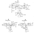
- FIG. ll is a simplified circuit diagram of a three-terminal parallel two-circuit transmission line, illustrating the above-described 44S method.
- circuits fl and f2 are connected between a sending end A and a receiving end B having a two-circuit branch point T from which the circuits fl and f2 branch off to a receiving end C.
- a load LB is connected with the receiving end B and a load LC with the receiving end C.
- x is a distance from the sending end A to a fault point in Fig. 11A or a distance from the branch point T to a fault point in Figs. llB and 11C;
- l a is a distance from the sending end A to the two-circuit branch point T;
- l b is a distance between the two-circuit branch point T and the receiving end B;
- l c is a distance between the two-circuit branch point T and the receiving end C;
- ⁇ is a positive sequence impedance per unit length of the transmission line;
- V ⁇ a and V ⁇ b are voltages of phases A and B, respectively, at the sending end A;
- V ⁇ af and V ⁇ bf are voltages of phases A and B, respectively, at a fault point;
- ⁇ al and ⁇ bl are currents of phases A and B of the circuit fl at the sending end A;
- ⁇ al' and ⁇ bl' are currents of phases A and B of the circuit f
- a distance x is determined for (l) a short-circuit in which the phase A is short-circuited to the phase B of the circuit fl between the sending end A and the two-circuit branch point T (Fig. llA), (2) a short-circuit in which the phase A is short-circuited to the phase B of the circuit fl between the receiving end B and the two-circuit branch point T (Fig. llB), and (3) a short-circuit in which the phase A is short-circuited to the phase B of the circuit fl between the receiving end C and the two-circuit branch point T (Fig. llC).
- the three equations include the positive sequence impedance to the fault point for the first term on the right hand side, as well as an error (V ⁇ af -V ⁇ bf)/( ⁇ al - ⁇ bl ) of the fault point due to a fault resistance, and errors x ⁇ ( ⁇ al'' - ⁇ bl'' )/( ⁇ al - ⁇ bl ) or x ⁇ ( ⁇ al' - ⁇ bl' )/( ⁇ al - ⁇ bl ) due to shunt current through a parallel line and a sound branch.
- (V ⁇ af - V ⁇ bf) is small when a short-circuit fault occurs, and ( ⁇ al - ⁇ bl ) includes the short-circuit current and the load current.
- the load current may be neglected.
- (Vaf - V ⁇ bf)/( ⁇ al - ⁇ bl ) is considered to be a resistance at a fault. Accordingly, by adopting the reactance component, the effects thereof can be nearly eliminated.
- the aforementioned methods of fault-localization for three-terminal parallel two-circuit transmission lines are capable of localizing a ground fault on three-terminal parallel two circuit transmission lines, but cannot be applied to parallel two-circuit transmission lines having more than three terminals.
- the parallel two-circuit transmission lines have often been of multiterminal systems, and there has been a need for a ground fault localization method that can generally be applied to n -terminal parallel two-circuit transmission lines.
- An example of such a method is the differential current protection method where current information at the respective terminals are transmitted to the main station by means of radio transmission or optical transmission, so that the fault localization may be performed on the basis of the current information at all the terminals.
- the invention is based in part on the recognition the this method allows the basic current data of the respective terminals to be available at the main station at all times, so that the analysis of the information from the occurrence of the fault until shutting off the line provides basic data necessary for locating a ground fault by the method of this invention.
- the present invention has been made in view of the above circumstances and has as an object to further develop the method in the previously mentioned patent applications and to provide a fault localization for an n -terminal parallel two-circuit transmission line, which is based on the current information on the respective terminals and is generally applicable to n-terminal parallel two-circuit transmission lines.
- the method of locating a fault point in a parallel two-circuit transmission line in an n-terminal system having a plurality of branches, connected to the transmission line at branch nodes, when a single fault occurs at one place in one circuit of the transmission line and when a multiple fault occurs at the same place in the two circuits, by calculating a distance to the fault point, of the present invention comprises the steps of:
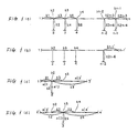
- Fig. 2 shows an n-terminal parallel two-circuit transmission line to which the present invention is applied.
- a terminals between the sending end or receiving end l (referred to as a terminals hereinafter) and a terminal n , there are a total of n-2 branch points including b2, b3, ...., b n-3 , b n-2 , b n-l .
- the branches are connected to terminals 2, 3, ... , n-l, respectively, via the two circuits fl and f2 of the transmission line.
- l l is the distance between the terminal l and the branch point b2, l2 the distance between the terminal 2 and the branch point b2, l3 the distance between the branch points b2 and b3, ...., l 2k-2 the distance between the terminal k and the branch point b k , and l 2k-l the distance between the branch points b k and b k+l .
- ⁇ ll is the positive sequence current flowing out of the terminal l in the circuit fl
- ⁇ l2 is the positive sequence current flowing out of the terminal l in the circuit f2
- ⁇ kl is the positive sequence current flowing out of the terminal k in the circuit f l
- ⁇ k2 is the positive sequence current flowing out of the terminal k in the circuit f2.
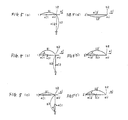
- Fig. 3 is a differential current equivalent circuit in terms of the positive sequence differential currents of the circuits in Fig. 2, in which the positive sequence differential currents ⁇ l , ⁇ 2, ..., ⁇ n are flowing out of the terminals l, 2, ..., n, respectively.
- Faults may be calssified by two cases as shown in Figs. 4(a) and 4(b). That is, when a ground fault is between the branch point b k and the terminal k, x is the distance between the terminal k and the fault point. When a fault occurs is between the branch points b k and b k+l , y is the distance from the branch b k to the fault point.
- Figs. 5(a) and 5(a') show the principle of equivalent-transformation, where a circuit (Fig. 5(a)) having the terminals l and 2 and the branch point b2 is transformed into a single circuit (Fig. 5(a')) having an imaginary terminal 2' without a branch.
- x is the actual distance from the terminal l to the fault point.
- the imaginary difference current ⁇ 2' and the imaginary distance l 2' are of the same values as in Fig. 5(a').
- the imaginary difference current ⁇ 2' and the distance l 2' are of the same value as in Fig. 5(a').
- the inverted L type differential current circuit in Fig. 5(a) can be transformed into a simple linear differential current circuit shown in Fig. 5(a') and the fault points in Figs. 5(b) and 5(c) can be transformed into the imaginary fault points in Fig. 5(b') and 5(c'), respectively.
- Figs. 5(d) and 5(e) are equivalent in that the voltages V ⁇ b2l and V ⁇ b22 at the branch points b 2l and b22 are equal and the currents ⁇ b2l and ⁇ b22 flowing out of the branch points b 2l and b22 are equal.
- Fig. l(a) is a duplicate of Fig. 3.
- the differential current equivalent circuit including this inverted L-type differential current circuit can be converted into a T-type three terminal parallel two-circuit transmission circuit as shown in Fig. l(c).
- the imaginary distance from the branch point b2 to the imaginary terminal 3' is represented by l 3' .
- the imaginary distance l 3' is determined by first transforming through the previously mentioned transformation technique the inverted L type differential current circuit having the terminals n and n-l and the branch point b n-1 into the linear equivalent circuit (imaginary distance is l n-l' ) having the imaginary terminal n-l' as shown in Fig. l(b), and then transforming the inverted I-type differential current circuit having the imaginary terminal n-l', terminal n-2, and the branch point b n-2 in Fig. l(b) into an equivalent circuit (imaginary distance is l n-2' ) having an imaginary terminal n-2', and thereafter the similar procedure is carried out one after another.
- the imaginary distance l 2' is determined by and the imaginary distance l 4' can be determined by the previously mentioned procedure in which the circuit in Fig. l(a) is transformed step by step from the right end. The aforementioned procedure of the previously filed Japanese Patent Application can be applied to the thus transformed circuit.
- the distance x from one of these terminals can be determined. If the fault point exists between the branch points b k and b k+l' , then the distance to the fault in that section can be determined as in the previously described calculation of y .
- a T equivalent circuit is written with respect to the branch point b2 on the left end of the difference current equivalent circuit in Fig. l(a). Thereafter, T equivalent circuits are written one after another with respect to the branch points b2, b3, b4, ... until the fault point is located.
- a T equivalent circuit may first be written with respect to the branch point b n-l on the right end, and thereafter the T equivalent circuits are written one after another with respect to the branch points b2, b3, b4, ... until the fault point is located.
- T equivalent circuit is first written with respect to an arbitrary branch point b k and thereafter T equivalent circuits are written one after another with respect to branch points b k+l , b k+2 , b k+3 . ... and with respect to branch points b k-l , b k-2 , b k-3 , .... until the fault point is located.
- Fig. 6 shows a fault locator connected to a four-terminal parallel two-circuit transmission line to which a fault localization according to the present invention is applied.
- a main unit is connected with the line at the sending end l and terminal units at the receiving ends 2, 3, and 4.
- the main unit at the sending end l includes a CT (current transformer) ll for detecting the currents ⁇ la , ⁇ lb , and ⁇ lc of the phases A, B, and C, respectively, of the circuit fl, a CT l2 for detecting the currents ⁇ 2a , ⁇ 2b , and ⁇ 2c of the phases A, B, and C of the circuit f2, an input port l3 for receiving the currents ⁇ la , ⁇ lb , and ⁇ lc detected by the CT ll, and ⁇ 2a , ⁇ 2b , ⁇ 2c detected by CT l2 and for isolating these currents from each other using an auxiliary CT not shown, an A/D converter l4 for converting the current signal of a predetermined level from the input port l3 into a digital data at a predetermined sampling rate, a data memory l5 for storing the digital data converted by the A/D converter l4, a CPU l6
- the receiving end 2 includes a CT 2l for detecting the currents ⁇ la , ⁇ lb , and ⁇ lc of the phases A, B, and C, flowing in the circuit fl, a CT 22 for detecting the currents ⁇ 2a , ⁇ 2b , and ⁇ 2c of the phase A, B, and C, respectively, flowing in the circuit f2, an input port 23 for performing the same task as the input port l3, an A/D converter 24, a data memory 25, a CPU 26, and a data-transmitting/receiving port 27.
- the receiving end 3 is provided with a CT 3l for detecting the currents ⁇ la , ⁇ lb , and ⁇ lc of the respective phases flowing in the circuit fl, a CT 32 for detecting the currents ⁇ 2a , ⁇ 2b , and ⁇ 2c of the respective phases flowing the circuit f2, an input port 33 for performing the same task as the input port l3, an A/D converter 34, a data memory 35, a CPU 36, and a data-transmitting/receiving port 37.
- the receiving end 4 is provided with a CT 4l for detecting the currents ⁇ la , ⁇ lb , and ⁇ lc of the respective phases flowing in the circuit fl, a CT 42 for detecting the currents ⁇ 2a , ⁇ 2b , and ⁇ 2c of the respective phases flowing the circuit f2, an input port 43, an A/D converter 44, a data memory 45, a CPU 46, and a data-transmitting/receiving port 47.
- a CT 4l for detecting the currents ⁇ la , ⁇ lb , and ⁇ lc of the respective phases flowing in the circuit fl
- CT 42 for detecting the currents ⁇ 2a , ⁇ 2b , and ⁇ 2c of the respective phases flowing the circuit f2
- an input port 43 an A/D converter 44, a data memory 45, a CPU 46, and a data-transmitting/receiving port 47.
- a fault localization apparatus of the above-described construction operates as follows: The currents flowing in the circuits fl and f2 at the terminals l-4 detected by the CT's ll, l2, 2l, 22, 32, 32, 4l, and 42 are transformed into the corresponding current signals which in turn are converted into digital data at a predetermined sampling rate by the A/D converters 4, 24, 34, and 44 and are then stored into the data memories l5, 25, 35, and 45.
- the CPU l6, 26, 36, and 46 calculate the positive-phase currents ⁇ ll , ⁇ l2 , ⁇ 2l , ⁇ 3l , ⁇ 32, ⁇ 4l , and ⁇ 42. Then, the respective CPUs l6, 26, 36, and 46 determine the zero-phase difference currents ⁇ l' , ⁇ 2, ⁇ 3, and ⁇ 4, respectively, of the two circuits fl and f2 using the following equations.
- I ⁇ l I ⁇ ll - I ⁇ l2
- I ⁇ 2 I ⁇ 2l - I ⁇ 22
- I ⁇ 3 I ⁇ l3l - I ⁇ 32
- I ⁇ 4 I ⁇ 4l - I ⁇ 42.
- the CPU l6 on the side of the sending and l recognizes that a fault has occurred, and requests the data-transmitting/receiving ports 27, 37, and 47 of sending to the data-transmitting/receiving port l7 the zero-phase current data ⁇ 2, ⁇ 3, and ⁇ 4 in the two circuits f l and f2 detected at the receiving ends 2-4.
- the data ⁇ 2, ⁇ 3, and ⁇ 4 are sent from the data-transmitting/receiving ports 27, 37, and 47 to the CPU l6 via the data-transmitting/receiving ports l7.
- the CPU l6 locates the fault using the ⁇ 4 calculated at the sending end l and the ⁇ 2, ⁇ 3, and ⁇ 4 of the receiving ends 2, 3, and 4 supplied through the transmitting/receiving port l7.
- Fig. 7 is a flowchart showing the procedure for the aforementioned CPU l6 to locate a fault.
- the inverted L type difference current circuit including the receiving ends 4, 3, and the branch b3 is transformed into a linear equivalent circuit (imaginary distance is l 3' ) having an imaginary receiving end 3' so as to form a T equivalent having the sending end I, receiving end 2, and imaginary receiving end 3' (refer to Fig. 1(c)).
- the distance x to the fault point is determined by the equation
- x is the distance from the sending end l to the fault point.
- step 4 determines a distance to the fault point seen from the receiving end 2. If x ⁇ l2, then the fault point should be between the receiving end 2 and the branch b2. Thus, x is the distance from the receiving end 2 to the fault point. If x>l 2' the procedure proceeds to steps 6 and 7. At step 6, the distance from the imaginary receiving end 3' to the fault point is determined and is then compared with the imaginary distance l 3' at step 7. The fault point is decided as not being between the sending end l and the branch b2 and not be between the receiving end 2 and the branch b2 Thus, the fault point seems to theoretically exist within the imaginary distance l 3' from the imaginary receiving end 3'. Thus, the fault point should be x ⁇ l 3' in Fig. 6. In this sense, the steps 6 and 7 may be omitted.
- the inverted L-type difference current circuit is transformed into a T equivalent circuit having the receiving ends 3 and 4 and imaginary terminal 2'.
- This T equivalent circuit is different from Fig. l(d) in that the imaginary receiving end 4' is replaced with the true receiving end 4. This is because the embodiment in Fig. 6 assumes that the sending end has only two branches b2 and b3.
- the distance x from the receiving end 4 to the fault is calculated.
- the fault port can be expected to be between the branch b3 and the receiving end 4. If x>l5, then a decision is made where the fault is with reference to the receiving end 3 at step ll.
- x may be interpreted to exist the distance from the receiving end 3 to the fault point.
- the embodiment was set such that the fault exists between the receiving end 3 and the branch 3, thus "YES" was selected at step l2.
- the distance x from the receiving end to the fault can be determined.
- the fault can be located in this section and therefore the distance y from the branch b k may be determined.
- the ground fault point in the ordinary n terminal parallel two-circuit transmission line may be located exactly using the current information on the respective terminals.
Landscapes
- Locating Faults (AREA)
- Emergency Protection Circuit Devices (AREA)
Applications Claiming Priority (4)
| Application Number | Priority Date | Filing Date | Title |
|---|---|---|---|
| JP14382490A JP2532155B2 (ja) | 1990-05-31 | 1990-05-31 | n端子平行2回線送電線における故障点標定方法 |
| JP143825/90 | 1990-05-31 | ||
| JP143824/90 | 1990-05-31 | ||
| JP2143825A JP2532156B2 (ja) | 1990-05-31 | 1990-05-31 | n端子平行2回線送電線における故障点標定方法 |
Publications (3)
| Publication Number | Publication Date |
|---|---|
| EP0459522A2 true EP0459522A2 (de) | 1991-12-04 |
| EP0459522A3 EP0459522A3 (en) | 1992-09-30 |
| EP0459522B1 EP0459522B1 (de) | 1995-12-20 |
Family
ID=26475443
Family Applications (1)
| Application Number | Title | Priority Date | Filing Date |
|---|---|---|---|
| EP91108973A Expired - Lifetime EP0459522B1 (de) | 1990-05-31 | 1991-05-31 | Fehlerlokalisierungsverfahren paralleler Doppelübertragungsleitungen mit N-Ausgängen |
Country Status (3)
| Country | Link |
|---|---|
| US (1) | US5485394A (de) |
| EP (1) | EP0459522B1 (de) |
| DE (1) | DE69115562T2 (de) |
Cited By (9)
| Publication number | Priority date | Publication date | Assignee | Title |
|---|---|---|---|---|
| CN104849616A (zh) * | 2015-05-15 | 2015-08-19 | 国家电网公司 | 基于虚拟功率比较原理配网单相接地故障选线方法 |
| CN104849617A (zh) * | 2015-05-15 | 2015-08-19 | 国家电网公司 | 利用虚拟功率最大原理实现配网单相故障选线方法 |
| CN108776284A (zh) * | 2018-03-29 | 2018-11-09 | 广东电网有限责任公司惠州供电局 | 一种基于零序电流比较的小电阻接地系统单相接地故障保护方法 |
| CN109103852A (zh) * | 2018-03-19 | 2018-12-28 | 中国石油大学(华东) | 一种基于零序电流比较的小电阻接地系统单相接地故障保护新方法 |
| CN110609207A (zh) * | 2019-09-10 | 2019-12-24 | 国电南瑞科技股份有限公司 | 一种t接线路故障测距方法 |
| CN110988604A (zh) * | 2019-12-30 | 2020-04-10 | 武汉理工大学 | 一种配电网单相接地故障选相方法 |
| CN113671314A (zh) * | 2021-08-17 | 2021-11-19 | 华北电力大学 | 一种配电网环网单相接地故障区段定位及测距方法 |
| CN114325211A (zh) * | 2021-11-05 | 2022-04-12 | 青岛科技大学 | 一种混合多端直流输电线路的故障定位方法 |
| CN114675124A (zh) * | 2022-02-23 | 2022-06-28 | 国电南瑞科技股份有限公司 | 一种四端线路故障双端测距方法与系统 |
Families Citing this family (21)
| Publication number | Priority date | Publication date | Assignee | Title |
|---|---|---|---|---|
| GB2286088B (en) * | 1994-01-26 | 1997-09-24 | Gec Alsthom Ltd | A method of locating the position of a fault on a power transmission line |
| GB2345810B (en) * | 1999-01-13 | 2003-07-23 | Alstom Uk Ltd | Fault-detection apparatus |
| US6256592B1 (en) * | 1999-02-24 | 2001-07-03 | Schweitzer Engineering Laboratories, Inc. | Multi-ended fault location system |
| US6325223B1 (en) | 1999-03-26 | 2001-12-04 | Patwin Plastics, Inc. | Display wall section |
| US6466030B2 (en) * | 2000-12-29 | 2002-10-15 | Abb Power Automation Ltd. | Systems and methods for locating faults on a transmission line with a single tapped load |
| US6466031B1 (en) * | 2000-12-29 | 2002-10-15 | Abb Power Automation Ltd. | Systems and methods for locating faults on a transmission line with multiple tapped loads |
| US6888708B2 (en) | 2001-06-20 | 2005-05-03 | Post Glover Resistors, Inc. | Method and apparatus for control and detection in resistance grounded electrical systems |
| GB0127745D0 (en) * | 2001-11-20 | 2002-01-09 | Alstom | Protection of double circuit power lines |
| US20060152866A1 (en) * | 2005-01-13 | 2006-07-13 | Gabriel Benmouyal | System for maintaining fault-type selection during an out-of-step condition |
| US8131485B2 (en) * | 2005-09-14 | 2012-03-06 | Abb Technology Ag | Method for fault location in electric power lines |
| US20080125984A1 (en) * | 2006-09-25 | 2008-05-29 | Veselin Skendzic | Spatially Assisted Fault Reporting Method, System and Apparatus |
| WO2013038176A2 (en) | 2011-09-12 | 2013-03-21 | Metroic Limited | Current measurement |
| GB201120295D0 (en) | 2011-11-24 | 2012-01-04 | Metroic Ltd | Current measurement apparatus |
| CN103199507A (zh) * | 2012-01-04 | 2013-07-10 | 河北省电力公司 | 一种基于改进紧邻集法的整定计算极端方式选择方法 |
| RU2492565C1 (ru) * | 2012-07-17 | 2013-09-10 | Общество с ограниченной ответственностью "Исследовательский центр "Бреслер" | Способ определения места повреждения линии электропередачи при двухстороннем наблюдении |
| RU2518050C1 (ru) * | 2012-12-26 | 2014-06-10 | Открытое акционерное общество "Научно-технический центр Единой энергетической системы" (ОАО "НТЦ ЕЭС") | Способ выявления участка повреждения при коротких замыканиях на кабельно-воздушной линии электропередачи постоянного тока |
| CN103163427B (zh) * | 2013-03-07 | 2015-07-01 | 福建省电力有限公司 | 利用沿线电压降实部分布特性实现线路单相接地故障单端测距方法 |
| RU2521968C1 (ru) * | 2013-03-18 | 2014-07-10 | Федеральное государственное бюджетное образовательное учреждение высшего профессионального образования "Орловский государственный аграрный университет" (ФГБОУ ВПО ОрелГАУ) | Способ выявления поврежденного участка в секционированной линии кольцевой сети |
| CN103675608A (zh) * | 2013-12-23 | 2014-03-26 | 华北电力大学 | 平行线路跨线路不接地故障点的计算方法 |
| CN107202936B (zh) * | 2017-05-04 | 2020-02-21 | 许继集团有限公司 | 一种t接线路故障测距方法 |
| WO2019186490A1 (en) * | 2018-03-31 | 2019-10-03 | Abb Schweiz Ag | Method and device for protection in a multi-terminal power transmission system |
Family Cites Families (9)
| Publication number | Priority date | Publication date | Assignee | Title |
|---|---|---|---|---|
| JPS52100149A (en) * | 1976-02-18 | 1977-08-22 | Tokyo Electric Power Co Inc:The | Digital failure point evaluating unit |
| JPS5830554B2 (ja) * | 1978-11-13 | 1983-06-29 | 東京電力株式会社 | 送電線故障点探査・送電線保護用の故障点標定方式 |
| US4455612A (en) * | 1982-01-27 | 1984-06-19 | Iowa State University Research Foundation, Inc. | Recursive estimation in digital distance relaying system |
| SE451102B (sv) * | 1985-12-20 | 1987-08-31 | Asea Ab | Forfarande for detektering av hogresistivt jordfel pa en kraftledning belegen mellan tva stationer samt anordning for genomforande av det nemnda forfarandet |
| AU603871B2 (en) * | 1987-03-03 | 1990-11-29 | Mitsubishi Denki Kabushiki Kaisha | Digital locator |
| US4812995A (en) * | 1987-05-19 | 1989-03-14 | Girgis Adly A | Adaptive Kalman Filtering in fault classification |
| JPH07122651B2 (ja) * | 1988-07-07 | 1995-12-25 | 日新電機株式会社 | 高抵抗系3端子平行2回線送電線における地絡故障点標定方法 |
| GB2222688B (en) * | 1988-09-09 | 1992-12-23 | Gen Electric Co Plc | Equipment for and methods of locating the position of a fault on a power transmission line |
| JPH0750145B2 (ja) * | 1988-12-05 | 1995-05-31 | 関西電力株式会社 | 平行2回線送電線の故障点標定方法 |
-
1991
- 1991-05-31 EP EP91108973A patent/EP0459522B1/de not_active Expired - Lifetime
- 1991-05-31 DE DE69115562T patent/DE69115562T2/de not_active Expired - Fee Related
-
1995
- 1995-05-18 US US08/443,765 patent/US5485394A/en not_active Expired - Fee Related
Cited By (11)
| Publication number | Priority date | Publication date | Assignee | Title |
|---|---|---|---|---|
| CN104849616A (zh) * | 2015-05-15 | 2015-08-19 | 国家电网公司 | 基于虚拟功率比较原理配网单相接地故障选线方法 |
| CN104849617A (zh) * | 2015-05-15 | 2015-08-19 | 国家电网公司 | 利用虚拟功率最大原理实现配网单相故障选线方法 |
| CN109103852A (zh) * | 2018-03-19 | 2018-12-28 | 中国石油大学(华东) | 一种基于零序电流比较的小电阻接地系统单相接地故障保护新方法 |
| CN108776284A (zh) * | 2018-03-29 | 2018-11-09 | 广东电网有限责任公司惠州供电局 | 一种基于零序电流比较的小电阻接地系统单相接地故障保护方法 |
| CN108776284B (zh) * | 2018-03-29 | 2020-12-04 | 广东电网有限责任公司惠州供电局 | 一种小电阻接地系统单相接地故障保护方法 |
| CN110609207A (zh) * | 2019-09-10 | 2019-12-24 | 国电南瑞科技股份有限公司 | 一种t接线路故障测距方法 |
| CN110609207B (zh) * | 2019-09-10 | 2021-09-10 | 国电南瑞科技股份有限公司 | 一种t接线路故障测距方法 |
| CN110988604A (zh) * | 2019-12-30 | 2020-04-10 | 武汉理工大学 | 一种配电网单相接地故障选相方法 |
| CN113671314A (zh) * | 2021-08-17 | 2021-11-19 | 华北电力大学 | 一种配电网环网单相接地故障区段定位及测距方法 |
| CN114325211A (zh) * | 2021-11-05 | 2022-04-12 | 青岛科技大学 | 一种混合多端直流输电线路的故障定位方法 |
| CN114675124A (zh) * | 2022-02-23 | 2022-06-28 | 国电南瑞科技股份有限公司 | 一种四端线路故障双端测距方法与系统 |
Also Published As
| Publication number | Publication date |
|---|---|
| EP0459522B1 (de) | 1995-12-20 |
| US5485394A (en) | 1996-01-16 |
| DE69115562T2 (de) | 1996-05-02 |
| EP0459522A3 (en) | 1992-09-30 |
| DE69115562D1 (de) | 1996-02-01 |
Similar Documents
| Publication | Publication Date | Title |
|---|---|---|
| EP0459522A2 (de) | Fehlerlokalisierungsverfahren paralleler Doppelübertragungsleitungen mit N-Ausgängen | |
| US4314199A (en) | Method for locating a fault point on a transmission line | |
| US5455776A (en) | Automatic fault location system | |
| EP1172660B9 (de) | Verfahren und Vorrichtung zur Fehlerortung in Versorgungsnetzen | |
| EP1020729B1 (de) | Fehlererkennung an Versorgungsleitungen | |
| US11169195B2 (en) | Identification of faulty section of power transmission line | |
| WO1995024014A2 (en) | One-terminal data fault location system | |
| EP0671011A1 (de) | Verfahren und vorrichtung zur feststellung des abstandes zwischen einer messstation und einer störung auf einer übertragungslinie | |
| US11035897B2 (en) | Method and device for fault section identification in multi-terminal mixed lines | |
| CN102484365A (zh) | 故障相选择和故障类型确定的方法 | |
| US6420876B1 (en) | Fault location in a medium-voltage network | |
| US4261038A (en) | Protection of electrical power supply systems | |
| EP0464662A1 (de) | Verfahren und Mittel zur Fehlerlokalisation in einem Netzwerk mit mehreren Endstationen | |
| JP2000074978A (ja) | 平行2回線送電線における故障点標定装置 | |
| Kumar et al. | Fuzzy approach to fault classification for transmission line protection | |
| JPH06347503A (ja) | 地絡故障点標定装置 | |
| RU2066511C1 (ru) | Дистанционный способ защиты и автоматики линии электропередачи | |
| JPH0219779A (ja) | 高抵抗系3端子平行2回線送電線における地絡故障点標定方法 | |
| EP4276480A1 (de) | Verfahren und schutzgerät zum erkennen eines einphasigen erdschlusses | |
| JP2984294B2 (ja) | 3端子平行2回線送電線の短絡故障点標定方法 | |
| JPS6039571A (ja) | 平行多回線地絡故障点標定装置 | |
| JP2002064926A (ja) | 電力系統用の保護リレー装置 | |
| JPH1090341A (ja) | 故障点標定方法 | |
| JP3503274B2 (ja) | 並行2回線送配電線の故障点標定方法 | |
| Kolla | Application of Modal Transformation for Fault Analysis and Digital Distance Relaying |
Legal Events
| Date | Code | Title | Description |
|---|---|---|---|
| PUAI | Public reference made under article 153(3) epc to a published international application that has entered the european phase |
Free format text: ORIGINAL CODE: 0009012 |
|
| AK | Designated contracting states |
Kind code of ref document: A2 Designated state(s): DE FR GB SE |
|
| PUAL | Search report despatched |
Free format text: ORIGINAL CODE: 0009013 |
|
| AK | Designated contracting states |
Kind code of ref document: A3 Designated state(s): DE FR GB SE |
|
| 17P | Request for examination filed |
Effective date: 19921222 |
|
| 17Q | First examination report despatched |
Effective date: 19940201 |
|
| GRAA | (expected) grant |
Free format text: ORIGINAL CODE: 0009210 |
|
| AK | Designated contracting states |
Kind code of ref document: B1 Designated state(s): DE FR GB SE |
|
| REF | Corresponds to: |
Ref document number: 69115562 Country of ref document: DE Date of ref document: 19960201 |
|
| ET | Fr: translation filed | ||
| PLBE | No opposition filed within time limit |
Free format text: ORIGINAL CODE: 0009261 |
|
| STAA | Information on the status of an ep patent application or granted ep patent |
Free format text: STATUS: NO OPPOSITION FILED WITHIN TIME LIMIT |
|
| 26N | No opposition filed | ||
| REG | Reference to a national code |
Ref country code: GB Ref legal event code: IF02 |
|
| PGFP | Annual fee paid to national office [announced via postgrant information from national office to epo] |
Ref country code: SE Payment date: 20030507 Year of fee payment: 13 |
|
| PGFP | Annual fee paid to national office [announced via postgrant information from national office to epo] |
Ref country code: FR Payment date: 20030508 Year of fee payment: 13 |
|
| PGFP | Annual fee paid to national office [announced via postgrant information from national office to epo] |
Ref country code: GB Payment date: 20030528 Year of fee payment: 13 |
|
| PGFP | Annual fee paid to national office [announced via postgrant information from national office to epo] |
Ref country code: DE Payment date: 20030612 Year of fee payment: 13 |
|
| PG25 | Lapsed in a contracting state [announced via postgrant information from national office to epo] |
Ref country code: GB Free format text: LAPSE BECAUSE OF NON-PAYMENT OF DUE FEES Effective date: 20040531 |
|
| PG25 | Lapsed in a contracting state [announced via postgrant information from national office to epo] |
Ref country code: SE Free format text: LAPSE BECAUSE OF NON-PAYMENT OF DUE FEES Effective date: 20040601 |
|
| PG25 | Lapsed in a contracting state [announced via postgrant information from national office to epo] |
Ref country code: DE Free format text: LAPSE BECAUSE OF NON-PAYMENT OF DUE FEES Effective date: 20041201 |
|
| GBPC | Gb: european patent ceased through non-payment of renewal fee | ||
| PG25 | Lapsed in a contracting state [announced via postgrant information from national office to epo] |
Ref country code: FR Free format text: LAPSE BECAUSE OF NON-PAYMENT OF DUE FEES Effective date: 20050131 |
|
| EUG | Se: european patent has lapsed | ||
| EUG | Se: european patent has lapsed | ||
| REG | Reference to a national code |
Ref country code: FR Ref legal event code: ST |