EP0459885A1 - Kompakt-Mehrzweckepiskop - Google Patents
Kompakt-Mehrzweckepiskop Download PDFInfo
- Publication number
- EP0459885A1 EP0459885A1 EP91401364A EP91401364A EP0459885A1 EP 0459885 A1 EP0459885 A1 EP 0459885A1 EP 91401364 A EP91401364 A EP 91401364A EP 91401364 A EP91401364 A EP 91401364A EP 0459885 A1 EP0459885 A1 EP 0459885A1
- Authority
- EP
- European Patent Office
- Prior art keywords
- episcope
- objective
- prism
- approximately
- reflector
- Prior art date
- Legal status (The legal status is an assumption and is not a legal conclusion. Google has not performed a legal analysis and makes no representation as to the accuracy of the status listed.)
- Granted
Links
- 230000004438 eyesight Effects 0.000 claims abstract description 26
- 230000003287 optical effect Effects 0.000 claims abstract description 18
- 230000004297 night vision Effects 0.000 claims abstract description 8
- 238000011282 treatment Methods 0.000 claims description 12
- 239000011521 glass Substances 0.000 claims description 7
- 229910000951 Aluminide Inorganic materials 0.000 claims description 5
- 230000005540 biological transmission Effects 0.000 claims description 4
- 230000003595 spectral effect Effects 0.000 claims description 4
- 238000006073 displacement reaction Methods 0.000 claims description 2
- 230000004913 activation Effects 0.000 claims 1
- 230000009849 deactivation Effects 0.000 claims 1
- 239000013307 optical fiber Substances 0.000 description 4
- 238000007789 sealing Methods 0.000 description 3
- 238000010586 diagram Methods 0.000 description 2
- 210000001747 pupil Anatomy 0.000 description 2
- 230000000007 visual effect Effects 0.000 description 2
- 238000010521 absorption reaction Methods 0.000 description 1
- 230000006978 adaptation Effects 0.000 description 1
- 230000003667 anti-reflective effect Effects 0.000 description 1
- 230000000721 bacterilogical effect Effects 0.000 description 1
- 230000001276 controlling effect Effects 0.000 description 1
- 230000008878 coupling Effects 0.000 description 1
- 238000010168 coupling process Methods 0.000 description 1
- 238000005859 coupling reaction Methods 0.000 description 1
- 230000006866 deterioration Effects 0.000 description 1
- 210000000887 face Anatomy 0.000 description 1
- 239000000835 fiber Substances 0.000 description 1
- 210000003128 head Anatomy 0.000 description 1
- 238000010438 heat treatment Methods 0.000 description 1
- 238000000034 method Methods 0.000 description 1
- 230000001681 protective effect Effects 0.000 description 1
- 230000001105 regulatory effect Effects 0.000 description 1
- 238000007650 screen-printing Methods 0.000 description 1
- 239000000126 substance Substances 0.000 description 1
- 239000013589 supplement Substances 0.000 description 1
- 238000010257 thawing Methods 0.000 description 1
- 230000007704 transition Effects 0.000 description 1
Images


Classifications
-
- G—PHYSICS
- G02—OPTICS
- G02B—OPTICAL ELEMENTS, SYSTEMS OR APPARATUS
- G02B23/00—Telescopes, e.g. binoculars; Periscopes; Instruments for viewing the inside of hollow bodies; Viewfinders; Optical aiming or sighting devices
- G02B23/02—Telescopes, e.g. binoculars; Periscopes; Instruments for viewing the inside of hollow bodies; Viewfinders; Optical aiming or sighting devices involving prisms or mirrors
- G02B23/08—Periscopes
-
- F—MECHANICAL ENGINEERING; LIGHTING; HEATING; WEAPONS; BLASTING
- F41—WEAPONS
- F41H—ARMOUR; ARMOURED TURRETS; ARMOURED OR ARMED VEHICLES; MEANS OF ATTACK OR DEFENCE, e.g. CAMOUFLAGE, IN GENERAL
- F41H5/00—Armour; Armour plates
- F41H5/26—Peepholes; Windows; Loopholes
- F41H5/266—Periscopes for fighting or armoured vehicles
-
- G—PHYSICS
- G02—OPTICS
- G02B—OPTICAL ELEMENTS, SYSTEMS OR APPARATUS
- G02B13/00—Optical objectives specially designed for the purposes specified below
- G02B13/16—Optical objectives specially designed for the purposes specified below for use in conjunction with image converters or intensifiers, or for use with projectors, e.g. objectives for projection TV
-
- G—PHYSICS
- G02—OPTICS
- G02B—OPTICAL ELEMENTS, SYSTEMS OR APPARATUS
- G02B23/00—Telescopes, e.g. binoculars; Periscopes; Instruments for viewing the inside of hollow bodies; Viewfinders; Optical aiming or sighting devices
- G02B23/12—Telescopes, e.g. binoculars; Periscopes; Instruments for viewing the inside of hollow bodies; Viewfinders; Optical aiming or sighting devices with means for image conversion or intensification
Definitions
- the invention relates to a multi-function episcope, which can in particular allow day vision with conventional optical means, and night vision, for example by means of a light intensifier tube.
- the invention finds particular application in observation devices for armored vehicles, and in particular for combat tanks. More generally, the episcope of the invention can be used in all cases where it is necessary to isolate the observer from the field observed, and where it is useful to have, on the one hand, means of direct vision by optical means. , and on the other hand electronic display means, comprising for example a light intensifier, an infrared detector or a camera, with CCD sensor or the like.
- the pilot has, for day vision, a conventional optical episcope, called day track, comprising an input reflector receiving the light rays, and an output reflector restoring the light rays to the pilot.
- a conventional optical episcope called day track
- the path of the light rays between the two reflectors can be direct or undergo one or more reflections.
- the daytime channel provides optimal vision, as long as there is sufficient light. However, it does not allow piloting at night. It is in fact not possible, at least in the combat position, to use lighting means integrated into the vehicle. It is therefore necessary to use an electronic night channel, comprising for example a lens, a light intensifier tube and an eyepiece.
- Another problem posed by this technique is the storage of the unused episcope in the passenger compartment of the vehicle, in which the space is most often very restricted. In addition, this unused episcope runs great risks of deterioration, if it is not properly secured.
- the invention aims to overcome these drawbacks of the state of the art.
- an objective of the invention is to provide a day-night episcope requiring a hole drilled in the shielding of the smallest possible size, and in particular, an orifice of size similar to that necessary for the passage of a simple day episcope.
- a particular objective is to provide such a day-night episcope ensuring maximum sealing at the level of the shielding.
- the invention also aims to provide such an episcope having no moving parts outside the shield and, more generally, few moving parts.
- Another object of the invention is to provide such an episcope occupying the smallest possible volume, so that it can be installed in many different vehicles, while leaving sufficient free space for the pilot. Indeed, the space available for an episcope, for example, in a battle tank, is very limited. Take into account, above the shielding, the passage of the turret and the protective stirrups, and below the shielding, the proximity of the steering wheel, the configuration and the open position of the door, the position conduct of the pilot in "head out" configuration, ...
- the purpose of the episcope of the invention is also to respect the ergonomic constraints, both with regard to the positioning of the exit prism of the daytime track and the eyepiece of the night track, which 'with regard to the switching means from one channel to another.
- the invention also aims to provide an episcope comprising on the one hand a conventional optical episcope and on the other hand electronic display means which may comprise a light intensifier, optical fibers, a CCD sensor, a thermal camera, etc. ...
- a multi-function episcope in particular for an armored vehicle, of the type comprising an optical vision device, based on reflectors.
- at least one electronic display device for example for night vision, comprising, between the input reflector and the output reflector of said optical vision device, means of reflection movable between two extreme positions, the first position allowing the free circulation of light rays between said input and output reflectors, and the second position causing the deflection of said light rays towards electronic processing means.
- the episcope is of the type passing through the shielding of said vehicle, the input reflector of said optical vision device being external to said vehicle.
- the part of the episcope external to the vehicle is reduced to the maximum, and identical to that emerging in the case of a single day episcope.
- the mobile part is limited, and located inside the vehicle, under the armor.
- said movable reflection means comprise a mirror, held by a movable stirrup, and means for guiding said stirrup between said extreme positions.
- the mobile bracket is configured so as not to interfere with the light rays, whatever its position.
- said guide means comprise a set of at least one link, arranged so as to ensure minimum horizontal and vertical clearance of said mirror during the travel of travel between said extreme positions.
- said electronic display device comprises a large aperture objective having a bend of approximately 90 ° in the downstream vicinity of the image.
- said objective comprises a set of multi-layer treated lenses and a prism.
- said objective comprises a field glass between said prism and said electronic processing means, the concave face of said field glass being treated with multiple layers.
- said objective has an aperture of approximately F / 1, a paraxial focal length of approximately 26 mm, an object field of approximately 45 ° and an image field with a diameter of about 20 mm.
- said objective has an enlarged useful spectral band, between approximately 450 nm and 900 nm.
- the episcope advantageously comprises means for controlling the passage of said reflection means from one of said extreme positions to the other, said control means jointly ensuring the setting in or outside of said electronic processing means.
- said electronic display device is a light intensification channel, comprising a large aperture objective, an intensifier tube and a biocular optic.
- said movable reflection means comprise a reflector, for example of the reflective prism type with triangular section, integral with said objective, the assembly of movable reflection means-objective being able to pivot about an axis substantially perpendicular to the plane defined by said assembly.
- the embodiment described below specifically relates to a day-night episcope, the night track of which comprises a light intensifier tube.
- the invention can be applied to other means of processing light rays.
- the light rays diverted by the removable mirror can be received by a camera lens, the image being reproduced on a display screen.
- FIG. 1 shows a day-night episcope, in particular intended for armored vehicles, such as combat tanks.
- This episcope comprises a housing 10, containing the two ways of day and night.
- the housing comprises an upper part 11, external to the shielding 12 of the vehicle, and closed by a porthole 13.
- This porthole 13 may include defrosting means, for example by an anti-reflective conductive interference treatment or a resistive screen printing.
- the part 11 external to the shielding comprises a single fixed reflector 14, common to the day and night channels, which is advantageously a prism of triangular section with total reflection or whose hypotenuse has received a reflecting treatment (aluminide, silvering or dielectric treatment ).
- This reflector can also be a mirror.
- the prism 14 is bonded to a prism 15 of generally parallelepiped shape, passing through the shielding 12.
- the prisms 14 and 15 can also form a single prism.
- the external and through parts only comprise fixed optical means, identical to those existing in daytime episcopes simple. This ensures perfect interchangeability of equipment, provided that the lower part of the housing is not too bulky. Such an episcope can therefore easily replace daytime periscopes in most existing armored vehicles.
- the lower part of the housing 10, under the shielding 12, includes the supplements for the day and night channels, and the means for switching from one channel to the other.
- the day track comprises, in addition to the prisms 14 and 15, an output reflector 16, which can advantageously be a prism of triangular section, which directs the light rays 17A towards the pilot 18.
- This prism 16 can be of total reflection or whose the hypotenuse received a reflective treatment (aluminide, silvering or dielectric treatment).
- a prism 19 of parallelepiped shape is glued to this triangular prism 16.
- the two parallelepiped prisms 15 and 19 are separated by a space 20, in which the retractable mirror 21 can move.
- the prisms 16 and 19 can also constitute a single prism.
- the light rays 17 pass successively through a first prism 14, a first parallelepipedal prism 15, an air space 20, a second parallelepipedic prism 19 and a second prism 16.
- the image seen by the pilot 18 is substantially equivalent to that obtained by means of a conventional episcope, with a single parallelepiped prism, without air space 20.
- this space 20, of small width does not bring no significant field reduction, this can be compensated by using for these prisms a higher index than usual, 1.62 for example.
- the daytime track can, in another embodiment, be more complex, and include for example more than two deviations of the light rays.
- the retractable mirror 21 is housed substantially parallel to the prism 19, in a space 22 provided for this purpose.
- This mirror is held by a stirrup 23, movable around an axis 24.
- the stirrup 23 is shaped so as not to influence the path of the spokes luminous.
- the position of the axis 24 was chosen precisely, so that the displacement of the mirror 21 requires a minimum of horizontal and vertical clearance, thus making it possible to reduce the space 20 between the two prisms 15 and 19 as much as possible, and the space 22 for housing the mirror in the day position.
- This lever 25 drives around its axis a rod 26, on which is fixed eccentrically a first end of a rod 27, the second end of which is fixed to the stirrup 23 for holding the mirror.
- a half-turn of the lever downwards therefore causes the mirror 21 to pass from the day position (FIG. 1) to the night position (FIG. 2). Conversely, the return to the high position of the lever 25 causes the return to the day track.
- the passage into the low position of the lever 25 causes, using for example a switch actuated by a cam integral with the lever, the automatic start of the electronic processing means, such as a light intensifier tube.
- the pilot switches from the daytime lane to the night lane. Conversely, the return to the daytime track leads to the cessation of these electronic means.
- Another solution for performing the day-night switching consists in making the mirror 21 of the lens 28 integral, and in rotating the lens 28 - mirror 21 assembly along an axis 31, so as to release, by rotation of 90 ° for example, the space between prisms 15 and 19 to allow day vision.
- the mirror 21 can then be replaced by a reflecting prism of triangular section.
- This configuration requires increasing the width of the episcope, but in particular allows, by the use of a high index prism to replace the mirror 21, to increase the field of vision at night.
- Figure 2 shows the episcope of the invention in the night position.
- the retractable mirror 21 is then placed between the two parallelepiped prisms 15 and 19, in the air space 20, so as to direct the light rays 17B towards a large aperture objective 28.
- entry prisms 14 and 15 are common to both day and night channels.
- the night track is, in the preferred embodiment described, a light intensification track.
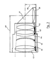
- the objective 28 is an angled objective, as described more precisely below in conjunction with FIG. 3.
- This angled objective makes it possible to position the light intensifier tube 29, necessary for night vision, high enough in the housing 10 so that the eyepiece 30 in which the image 17C is formed can be placed near the output prism 16 , so as to ensure the visual comfort of the pilot 18.
- the intensifier tube 29 can be of any type commercially available.
- it is a second generation tube, with electrostatic focusing and wafer of microchannels, such as, for example, the tube TH9311, marketed by THOMSON-CSF (registered trademark), the tube XX1380, marketed by PHILIPS (registered trademark), or the MX9644 / UV tube, sold in particular by THOMSON-CSF (registered trademark).
- the eyepiece 30 is advantageously a single biocular, which may for example have an exit pupil of about 80 mm in diameter, so as to offer great viewing comfort.
- This biocular has an apparent field of the order of 45 °, which corresponds to an object field of the night channel of 45 °, for an overall magnification of approximately 1.
- the biocular 30 can be directly coupled to the intensifier tube 29, using the image given on the screen of the latter. Clearly, to simplify the biocular or increase viewing comfort, this coupling can be carried out via a magnifying optical fiber, making it possible, for example, to go from a screen diameter of tube 29 to a diameter of upper biocular entry, 40 mm for example.
- optical fiber independent of the intensifier tube makes it possible to give a slight curvature to the exit face of the fiber, so as to improve the quality of the biocular 30, and in particular the field curvature.
- the biocular 30 can also be equipped with demisting means, such as a heating resistor placed in the eyepiece, or a conductive interference treatment deposited on one face of the eye lens of the biocular, the temperature of which is regulated by thermostat at about 35 °.
- demisting means such as a heating resistor placed in the eyepiece, or a conductive interference treatment deposited on one face of the eye lens of the biocular, the temperature of which is regulated by thermostat at about 35 °.
- the angled objective 28 makes it possible to significantly reduce the overall size of the episcope.
- Figure 3 shows a particular embodiment of such an objective.
- the useful spectral band covers a broad spectrum, corresponding to the visible domain and to the near infrared. It is between approximately 450 and 900 nm.
- This objective makes it possible to form the image of an object or of a landscape situated between infinity and 10 meters on the photocathode of the image intensifier tube 29.
- the 90 ° elbow is produced by a prism 41, 21 mm side.
- This prism 41 is integrated into the optical combination, which also includes six lenses 42 to 47 and a field lens 50.
- Table 1 presents all of the diopters used in this object, specifying their thicknesses, radii, indices and useful diameters.
- the distance 48 between the optical axis and the intensifier tube is 15 mm, and the length 49 from the front of the objective to the axis is less than 51 mm.
- the maximum useful diameter is 26.2 mm at the front, at the level of the pupil and is reduced to less than 25 mm in the area above the tube.
- the treatments used for the six lenses 41 to 47 are multi-layers optimized for high indices.
- the glasses used have an absorption negligible above 450 nm given the small thickness crossed.
- the transmission is thus greater than 90% in the entire spectral band 450 nm - 850 nm, for the objective only.
- the prism 41 undergoes the same multi-layer treatments on its inlet and outlet faces.
- the prism hypotenuse cannot work in total reflection, due to the large opening. It is therefore necessary to use a high-efficiency treatment so as not to penalize the overall transmission balance.
- the objective also comprises, between the prism 41 and the photocathode of the light intensifier tube 29, a field glass 50 bonded to the intensifier tube.
- the concave face of this field glass 50 is also treated with a multi-layer. the flat face is left bare, due to sticking.
- the device for electronic processing of light rays is not limited to a light intensifier. It can for example be any type of camera sensor, allowing viewing on a television-type screen, and particularly on a flat screen.
- viewing images from other sensors such as reversing cameras, thermal cameras, and complex information, such as maps, by day and by night.
- the retractable mirror can take one or more intermediate positions between the two extreme positions, so as to direct the light rays towards several distinct electronic devices.
Landscapes
- Physics & Mathematics (AREA)
- General Physics & Mathematics (AREA)
- Optics & Photonics (AREA)
- Astronomy & Astrophysics (AREA)
- Engineering & Computer Science (AREA)
- General Engineering & Computer Science (AREA)
- Telescopes (AREA)
- Instruments For Viewing The Inside Of Hollow Bodies (AREA)
Applications Claiming Priority (2)
| Application Number | Priority Date | Filing Date | Title |
|---|---|---|---|
| FR9006874A FR2662822B1 (fr) | 1990-06-01 | 1990-06-01 | Episcope multi-fonction, a faible encombrement. |
| FR9006874 | 1990-06-01 |
Publications (2)
| Publication Number | Publication Date |
|---|---|
| EP0459885A1 true EP0459885A1 (de) | 1991-12-04 |
| EP0459885B1 EP0459885B1 (de) | 1995-05-10 |
Family
ID=9397216
Family Applications (1)
| Application Number | Title | Priority Date | Filing Date |
|---|---|---|---|
| EP91401364A Expired - Lifetime EP0459885B1 (de) | 1990-06-01 | 1991-05-28 | Kompakt-Mehrzweckepiskop |
Country Status (5)
| Country | Link |
|---|---|
| EP (1) | EP0459885B1 (de) |
| CA (1) | CA2042419A1 (de) |
| DE (1) | DE69109538T2 (de) |
| FR (1) | FR2662822B1 (de) |
| NO (1) | NO911967L (de) |
Cited By (2)
| Publication number | Priority date | Publication date | Assignee | Title |
|---|---|---|---|---|
| FR2803917A1 (fr) * | 2000-01-19 | 2001-07-20 | Giat Ind Sa | Dispositif de vision jour/nuit |
| WO2015063480A1 (en) * | 2013-10-29 | 2015-05-07 | Kent Periscopes Ltd | Periscope |
Families Citing this family (3)
| Publication number | Priority date | Publication date | Assignee | Title |
|---|---|---|---|---|
| RU2158947C1 (ru) * | 2000-02-24 | 2000-11-10 | Акционерное общество открытого типа "Загорский оптико-механический завод" | Двухканальный прибор для дневного и ночного наблюдения |
| GB2489741B (en) * | 2011-04-08 | 2013-10-02 | Kent Periscopes Ltd | Enhanced periscope |
| IT202100014987A1 (it) * | 2021-06-09 | 2022-12-09 | M E S S P A | Sistema opto-elettronico a periscopio |
Citations (5)
| Publication number | Priority date | Publication date | Assignee | Title |
|---|---|---|---|---|
| FR2273291A1 (en) * | 1974-05-29 | 1975-12-26 | Sopelem | Periscope observation head for day or night viewing - has optical and opto-electronic devices and switching means in same head |
| DE2704185A1 (de) * | 1976-02-02 | 1978-03-16 | Rank Organisation Ltd | Tag/nacht-sichtgeraet |
| EP0192309A1 (de) * | 1985-02-22 | 1986-08-27 | Telecommunications Radioelectriques Et Telephoniques T.R.T. | Tag-Nacht-Sichtgerät |
| EP0193236A1 (de) * | 1985-02-22 | 1986-09-03 | Telecommunications Radioelectriques Et Telephoniques T.R.T. | Tag-Nachtsichtgerät mit weitem Sehfeld |
| EP0412828A2 (de) * | 1989-08-09 | 1991-02-13 | Noga Lite Ltd. | Tag/Nachtsichtgerät |
-
1990
- 1990-06-01 FR FR9006874A patent/FR2662822B1/fr not_active Expired - Lifetime
-
1991
- 1991-05-13 CA CA002042419A patent/CA2042419A1/en not_active Abandoned
- 1991-05-22 NO NO91911967A patent/NO911967L/no unknown
- 1991-05-28 DE DE69109538T patent/DE69109538T2/de not_active Expired - Lifetime
- 1991-05-28 EP EP91401364A patent/EP0459885B1/de not_active Expired - Lifetime
Patent Citations (5)
| Publication number | Priority date | Publication date | Assignee | Title |
|---|---|---|---|---|
| FR2273291A1 (en) * | 1974-05-29 | 1975-12-26 | Sopelem | Periscope observation head for day or night viewing - has optical and opto-electronic devices and switching means in same head |
| DE2704185A1 (de) * | 1976-02-02 | 1978-03-16 | Rank Organisation Ltd | Tag/nacht-sichtgeraet |
| EP0192309A1 (de) * | 1985-02-22 | 1986-08-27 | Telecommunications Radioelectriques Et Telephoniques T.R.T. | Tag-Nacht-Sichtgerät |
| EP0193236A1 (de) * | 1985-02-22 | 1986-09-03 | Telecommunications Radioelectriques Et Telephoniques T.R.T. | Tag-Nachtsichtgerät mit weitem Sehfeld |
| EP0412828A2 (de) * | 1989-08-09 | 1991-02-13 | Noga Lite Ltd. | Tag/Nachtsichtgerät |
Cited By (4)
| Publication number | Priority date | Publication date | Assignee | Title |
|---|---|---|---|---|
| FR2803917A1 (fr) * | 2000-01-19 | 2001-07-20 | Giat Ind Sa | Dispositif de vision jour/nuit |
| EP1118895A1 (de) * | 2000-01-19 | 2001-07-25 | Giat Industries | Tag- und Nachtsichtgerät |
| WO2015063480A1 (en) * | 2013-10-29 | 2015-05-07 | Kent Periscopes Ltd | Periscope |
| US9915817B2 (en) | 2013-10-29 | 2018-03-13 | Kent Periscopes Ltd | Periscope with a reflector forming a light tight seal |
Also Published As
| Publication number | Publication date |
|---|---|
| DE69109538T2 (de) | 1995-09-07 |
| DE69109538D1 (de) | 1995-06-14 |
| NO911967L (no) | 1991-12-02 |
| FR2662822B1 (fr) | 1993-05-14 |
| EP0459885B1 (de) | 1995-05-10 |
| FR2662822A1 (fr) | 1991-12-06 |
| CA2042419A1 (en) | 1991-12-02 |
| NO911967D0 (no) | 1991-05-22 |
Similar Documents
| Publication | Publication Date | Title |
|---|---|---|
| EP0511058B1 (de) | Optischer Mischer für Helmanzeige | |
| US3464757A (en) | Day-night optical viewing device | |
| EP0127644A1 (de) | Sonnenfilter für eine anzeigeeinrichtung mit diffraktionsoptik. | |
| SE533391C2 (sv) | Kombinationssikte | |
| FR2581459A1 (fr) | Dispositif de transport et de combinaison d'images lumineuses, et son utilisation pour un viseur de casque | |
| EP0767925B1 (de) | Kompaktes zweiäugiges nachtsichtfernrohr | |
| FR2769721A1 (fr) | Dispositif optique pour viseur de casque comportant un miroir de mangin | |
| EP0459885B1 (de) | Kompakt-Mehrzweckepiskop | |
| EP0193236B1 (de) | Tag-Nachtsichtgerät mit weitem Sehfeld | |
| FR2712993A1 (fr) | Système de vision. | |
| EP0475797B1 (de) | Optisches System mit grossem Blickfeld und grosser Öffnung, insbesondere für den Nachtsichtkanal eines Episkops und mit einem solchen optischen System ausgerüstetes Episkop | |
| US20240085604A1 (en) | Optical system for periscope camera module | |
| EP0025398B1 (de) | Optisches System mit mehreren Vergrösserungen | |
| JP4786154B2 (ja) | 反射防止膜を設けた光学素子を備えた顕微鏡 | |
| EP0065457B1 (de) | Periskop für U-Boote mit mehreren Beobachtungsköpfen | |
| JPH02308120A (ja) | ディスプレイ装置 | |
| FR2687795A1 (en) | Optoelectric system for the detection and angular location of a luminous object | |
| EP1324098B1 (de) | Optische Visiervorrichtung für einem Kampffahrzeug | |
| WO2001067153A2 (fr) | Relais optique correcteur d'aberrations pour systeme optique, notamment telescope a miroirs | |
| WO2021078513A1 (fr) | Afficheur tête-haute | |
| FR2547428A1 (fr) | Dispositif d'observation optique a deux champs | |
| EP0703481A1 (de) | Tag-Nacht Episkop | |
| EP0463929A1 (de) | Mechanisches Gelenkträgerelement insbesondere für ein Episkop, und Episkop, das auf ein solches Trägerelement montiert wird | |
| FR2851054A1 (fr) | Telescope optique de grand champ et en particulier pour l'observation astronomique a partir d'un satellite | |
| FR2472762A1 (fr) | Dispositif de vision binoculaire de jour |
Legal Events
| Date | Code | Title | Description |
|---|---|---|---|
| PUAI | Public reference made under article 153(3) epc to a published international application that has entered the european phase |
Free format text: ORIGINAL CODE: 0009012 |
|
| AK | Designated contracting states |
Kind code of ref document: A1 Designated state(s): CH DE GB IT LI NL SE |
|
| 17P | Request for examination filed |
Effective date: 19920504 |
|
| 17Q | First examination report despatched |
Effective date: 19940120 |
|
| GRAA | (expected) grant |
Free format text: ORIGINAL CODE: 0009210 |
|
| PGFP | Annual fee paid to national office [announced via postgrant information from national office to epo] |
Ref country code: CH Payment date: 19950413 Year of fee payment: 5 |
|
| AK | Designated contracting states |
Kind code of ref document: B1 Designated state(s): CH DE GB IT LI NL SE |
|
| PG25 | Lapsed in a contracting state [announced via postgrant information from national office to epo] |
Ref country code: IT Free format text: LAPSE BECAUSE OF FAILURE TO SUBMIT A TRANSLATION OF THE DESCRIPTION OR TO PAY THE FEE WITHIN THE PRE;WARNING: LAPSES OF ITALIAN PATENTS WITH EFFECTIVE DATE BEFORE 2007 MAY HAVE OCCURRED AT ANY TIME BEFORE 2007. THE CORRECT EFFECTIVE DATE MAY BE DIFFERENT FROM THE ONE RECORDED.SCRIBED TIME-LIMIT Effective date: 19950510 Ref country code: NL Free format text: LAPSE BECAUSE OF NON-PAYMENT OF DUE FEES Effective date: 19950510 |
|
| REF | Corresponds to: |
Ref document number: 69109538 Country of ref document: DE Date of ref document: 19950614 |
|
| PG25 | Lapsed in a contracting state [announced via postgrant information from national office to epo] |
Ref country code: SE Effective date: 19950810 |
|
| GBT | Gb: translation of ep patent filed (gb section 77(6)(a)/1977) |
Effective date: 19950720 |
|
| NLV1 | Nl: lapsed or annulled due to failure to fulfill the requirements of art. 29p and 29m of the patents act | ||
| PLBE | No opposition filed within time limit |
Free format text: ORIGINAL CODE: 0009261 |
|
| STAA | Information on the status of an ep patent application or granted ep patent |
Free format text: STATUS: NO OPPOSITION FILED WITHIN TIME LIMIT |
|
| 26N | No opposition filed | ||
| PG25 | Lapsed in a contracting state [announced via postgrant information from national office to epo] |
Ref country code: CH Effective date: 19960531 Ref country code: LI Effective date: 19960531 |
|
| REG | Reference to a national code |
Ref country code: CH Ref legal event code: PL |
|
| REG | Reference to a national code |
Ref country code: GB Ref legal event code: IF02 |
|
| PGFP | Annual fee paid to national office [announced via postgrant information from national office to epo] |
Ref country code: DE Payment date: 20100526 Year of fee payment: 20 |
|
| PGFP | Annual fee paid to national office [announced via postgrant information from national office to epo] |
Ref country code: GB Payment date: 20100526 Year of fee payment: 20 |
|
| REG | Reference to a national code |
Ref country code: DE Ref legal event code: R071 Ref document number: 69109538 Country of ref document: DE |
|
| REG | Reference to a national code |
Ref country code: GB Ref legal event code: PE20 Expiry date: 20110527 |
|
| PG25 | Lapsed in a contracting state [announced via postgrant information from national office to epo] |
Ref country code: GB Free format text: LAPSE BECAUSE OF EXPIRATION OF PROTECTION Effective date: 20110527 |
|
| PG25 | Lapsed in a contracting state [announced via postgrant information from national office to epo] |
Ref country code: DE Free format text: LAPSE BECAUSE OF EXPIRATION OF PROTECTION Effective date: 20110529 |