EP0460049B1 - Hilfsanordnung in fahrzeugen - Google Patents
Hilfsanordnung in fahrzeugen Download PDFInfo
- Publication number
- EP0460049B1 EP0460049B1 EP90903973A EP90903973A EP0460049B1 EP 0460049 B1 EP0460049 B1 EP 0460049B1 EP 90903973 A EP90903973 A EP 90903973A EP 90903973 A EP90903973 A EP 90903973A EP 0460049 B1 EP0460049 B1 EP 0460049B1
- Authority
- EP
- European Patent Office
- Prior art keywords
- vehicle
- drive
- unit
- control means
- auxiliary
- Prior art date
- Legal status (The legal status is an assumption and is not a legal conclusion. Google has not performed a legal analysis and makes no representation as to the accuracy of the status listed.)
- Expired - Lifetime
Links
- 230000008878 coupling Effects 0.000 claims abstract description 19
- 238000010168 coupling process Methods 0.000 claims abstract description 19
- 238000005859 coupling reaction Methods 0.000 claims abstract description 19
- 230000004913 activation Effects 0.000 claims description 6
- 230000005540 biological transmission Effects 0.000 claims 6
- 230000008901 benefit Effects 0.000 description 6
- 238000012423 maintenance Methods 0.000 description 5
- 239000010426 asphalt Substances 0.000 description 2
- 238000010276 construction Methods 0.000 description 2
- 230000001404 mediated effect Effects 0.000 description 2
- 244000118350 Andrographis paniculata Species 0.000 description 1
- 241000282414 Homo sapiens Species 0.000 description 1
- 230000003213 activating effect Effects 0.000 description 1
- 230000000712 assembly Effects 0.000 description 1
- 238000000429 assembly Methods 0.000 description 1
- 230000015572 biosynthetic process Effects 0.000 description 1
- 230000000694 effects Effects 0.000 description 1
- 239000012530 fluid Substances 0.000 description 1
- 230000007246 mechanism Effects 0.000 description 1
- 230000002093 peripheral effect Effects 0.000 description 1
- 230000001737 promoting effect Effects 0.000 description 1
- XLYOFNOQVPJJNP-UHFFFAOYSA-N water Substances O XLYOFNOQVPJJNP-UHFFFAOYSA-N 0.000 description 1
Images


Classifications
-
- B—PERFORMING OPERATIONS; TRANSPORTING
- B62—LAND VEHICLES FOR TRAVELLING OTHERWISE THAN ON RAILS
- B62D—MOTOR VEHICLES; TRAILERS
- B62D1/00—Steering controls, i.e. means for initiating a change of direction of the vehicle
- B62D1/02—Steering controls, i.e. means for initiating a change of direction of the vehicle vehicle-mounted
- B62D1/22—Alternative steering-control elements, e.g. for teaching purposes
-
- B—PERFORMING OPERATIONS; TRANSPORTING
- B60—VEHICLES IN GENERAL
- B60K—ARRANGEMENT OR MOUNTING OF PROPULSION UNITS OR OF TRANSMISSIONS IN VEHICLES; ARRANGEMENT OR MOUNTING OF PLURAL DIVERSE PRIME-MOVERS IN VEHICLES; AUXILIARY DRIVES FOR VEHICLES; INSTRUMENTATION OR DASHBOARDS FOR VEHICLES; ARRANGEMENTS IN CONNECTION WITH COOLING, AIR INTAKE, GAS EXHAUST OR FUEL SUPPLY OF PROPULSION UNITS IN VEHICLES
- B60K20/00—Arrangement or mounting of change-speed gearing control devices in vehicles
-
- B—PERFORMING OPERATIONS; TRANSPORTING
- B60—VEHICLES IN GENERAL
- B60T—VEHICLE BRAKE CONTROL SYSTEMS OR PARTS THEREOF; BRAKE CONTROL SYSTEMS OR PARTS THEREOF, IN GENERAL; ARRANGEMENT OF BRAKING ELEMENTS ON VEHICLES IN GENERAL; PORTABLE DEVICES FOR PREVENTING UNWANTED MOVEMENT OF VEHICLES; VEHICLE MODIFICATIONS TO FACILITATE COOLING OF BRAKES
- B60T7/00—Brake-action initiating means
- B60T7/02—Brake-action initiating means for personal initiation
-
- B—PERFORMING OPERATIONS; TRANSPORTING
- B60—VEHICLES IN GENERAL
- B60T—VEHICLE BRAKE CONTROL SYSTEMS OR PARTS THEREOF; BRAKE CONTROL SYSTEMS OR PARTS THEREOF, IN GENERAL; ARRANGEMENT OF BRAKING ELEMENTS ON VEHICLES IN GENERAL; PORTABLE DEVICES FOR PREVENTING UNWANTED MOVEMENT OF VEHICLES; VEHICLE MODIFICATIONS TO FACILITATE COOLING OF BRAKES
- B60T7/00—Brake-action initiating means
- B60T7/12—Brake-action initiating means for automatic initiation; for initiation not subject to will of driver or passenger
- B60T7/22—Brake-action initiating means for automatic initiation; for initiation not subject to will of driver or passenger initiated by contact of vehicle, e.g. bumper, with an external object, e.g. another vehicle, or by means of contactless obstacle detectors mounted on the vehicle
Definitions
- the present invention relates to an auxiliary vehicle control means by means of which a vehicle can be controlled from a site other than its driver's cabin location, said auxiliary vehicle control means being of the kind defined in the preamble of Claim 1.
- Vehicles of this kind are known to the art - see for instance WO Al 80/01154 (Wibom) - and have been used, among other things, in conjunction with road maintenance work for the purpose of facilitating the formation of holes by the sides of the road under maintenance, for the erection of posts intended for road fencing and the like.
- the driver of the vehicle positions himself outside the driver's cabin and is able to control the vehicle, i.e. drive and steer the vehicle, from any desired position with the aid of an operations console or panel.
- DE-A1-3 200 241 (Niklaus) describes an automatic control device - so-called autopilot - for a water craft or land based vehicle which is provided with a coupling device in the form of a helical spring which produces coupling engagement when the spring is extended as a result of being acted upon at either end.
- the coupling device is automatically disengaged when the standard control mechanism of the vehicle or watercraft is activated.
- auxiliary vehicle control means of the kind described enables the auxiliary vehicle control means to be used over a much wider field, therewith enabling the device to be used advantageously with a large number of different vehicles intended for mutually different purposes.
- one object of the present invention is to provide auxiliary vehicle control means of the aforedescribed kind which will enable a vehicle to be manoeuvred effectively and reliably from the alternative vehicle control site, and also auxiliary vehicle control means which is compatible with the standard vehicle drive-and-control system and which will afford improved safety, for instance when the vehicle is to be driven in a direction which corresonds to its standard reverse-drive direction.
- auxiliary vehicle control means will be superimposed operationally on the standard vehicle drive-and-control system, i.e. this latter system will be able to operate even when the auxiliary vehicle control means is engaged.
- vehicle drive-line is meant the chain of vehicle drive components from the engine to the rear axle.
- Another important advantage afforded by the invention is that the standard vehicle drive-and-control system need not be reconstructed or modified to any creat extent. Instead, the auxiliary vehicle control means can be fitted to the vehicle without needing to disturb the standard vehicle drive-and-control system to any great extent, this system thus remaining essentially unchanged.
- the front of the vehicle will preferably be fitted with a collision guard of the kind set forth in the preamble of Claim 2.
- the aspect of safety when driving a vehicle forward can also be improved by mounting a TV-camera on the forward part of the vehicle and providing the alternative operating location with a TV-monitor by means of which the driver is able to utilize the information mediated by the TV-camera.
- the arrangement defined in Claim 3 will enable the various units incorporated in the auxiliary vehicle control means to be activated readily from the driver's cabin.
- the coupling-engagement movement defined is effected by the driver of the vehicle with the aid of a device, such as the operating lever, wherewith the driver is able to leave the driver's cabin and position himself at the alternative operating location, so as to obtain full control over the vehicle through the operating unit of said auxiliary vehicle control means, subsequent to having manipulated the main current switch on the operations panel or console.
- Claim 4 defines a particularly operable construction of the control unit forming part of the auxiliary vehicle control means.
- the control unit will only occupy a small space in the driver's cabin and can be fitted to the steering wheel in a simple fashion.
- the aforesaid operating lever is readily accessible to the driver.
- the friction clutch or coupling ensures that the driver is able to steer the vehicle by means of the steering wheel, even though the auxiliary vehicle control means should be unintentionally engaged. In this case, however, considerable power will be needed to steer the vehicle.
- Uneven loading of the driving shaft can be avoided by using at least two motors with the drive unit, and it is also possible to obtain two mutually different operational states in a simple fashion, by coupling the motors alternatively in series or in parallel.
- the drive unit will preferably include a slip coupling in order to avoid damage to the drive unit, for instance should the drive unit be inadvertently engaged as the vehicle is moved forward with the aid of its standard drive line.
- a slip coupling will also ensure that when braking or releasing the "dead man's grip", the drive unit is able to slip relative to the drive line to a sufficient extent.
- the drive-unit motors may be electric motors or hydraulic motors. When hydraulic motors are used, the aforesaid slipping function can be achieved with the aid of an appropriate check valve arrangement.
- a pressure-fluid activated coupling arrangement preferably a pneumatic coupling arrangement, can be used for engaging the gearwheels of the drive unit, said gearwheels preferably being displaceable on splines provided on the outward shafts of respective drive motors.
- the inventive auxiliary vehicle control means can find use in many different types of vehicles, for instance garbage collection vehicles, aircraft catering vehicles, so-called sky-lifts, road maintenance vehicles and the like, for instance a hedge-clipping vehicle, a timber loader, an asphalt layer, a vehicle for setting-out verge markers on snowy roads, a road salvage vehicle or other types of crane-carrying vehicles, etc. It will be seen from this that the inventive auxiliary vehicle control means has a particularly wide range of use possibilities.
- Figure 1 is a side view of a refuse collection truck provided with an auxiliary vehicle control means according to the invention.
- Figure 2 is a view from above illustrating an operations panel or console forming part of the operating units of the auxiliary vehicle control means.
- Figure 3 is a side view of a control unit forming part of the auxiliary vehicle control means and connected to the steering wheel of the vehicle.
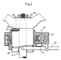
- FIG. 4 is a sectional view of the control unit illustrated in Figure 3.
- Figures 5a and 5b are views of a drive unit forming part of the auxiliary vehicle control means and connected to the cardan shaft of the vehicle.
- Figures 6-8 illustrate examples of vehicles with which an inventive auxiliary vehicle control means can be used to advantage.
- Figure 6 is a side view of a catering vehicle for aircraft catering on airfield complexes.
- Figure 7 is a perspective view of a so-called sky-lift.
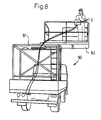
- Figure 8 is a perspective view of a road maintenance vehicle or like vehicle, more specifically a hedge clipping vehicle.
- FIGS 9 and 10 finally, illustrate a modified control unit.
- Figure 1 illustrates a refuse collection vehicle 1 which has mounted on its rear end an operations bridge 2 on which the driver of the vehicle can position himself and, while facing in the rearward direction of the vehicle, manoeuvre the vehicle with the aid of an inventive auxiliary vehicle control means.
- the auxiliary vehicle control means is operated with the aid of an operating unit 3 equipped with an operations console or panel 4, illustrated in Figure 2.
- the vehicle is also provided with a front collision guard, in the form of a grid or like construction 5, and a TV-camera 6 which scans the area in front of the vehicle driver's cabin, a monitor 7 which is connected to the TV-camera and which enables the driver, while on the bridge 2, to obtain the information mediated by the TV-camera 6.
- the platform 2 also carries two rear-view mirrors 8, so that the driver is able to see respective areas on both sides of the vehicle when driving the vehicle with the aid of said auxiliary vehicle control means.
- the operations console 4 on the operating unit 3 incorporates, among other things, the following operating means: a main electric supply switch 4a; an emergency stop 4b; control means 4c operative to steer the vehicle in one direction or the other, by engagement of the control unit incorporated in the auxiliary vehicle control means. Also provided is a control means 4d for driving the vehicle forwards or backwards, by engagement of said drive unit in one or the other direction.
- the console or panel 4 also includes two buttons 4e, 4f for activation of a drive direction indicator, means 4g for activating a hand brake, a signal button 4h and a means 4i for engaging and disengaging the vehicle brake system.
- the vehicle driver's cabin is also eguipped with control means for engaging and disengaging, among other things, electrical supply, drive unit, control unit, brakes and light signals and acoustic signals when driving forwards (not shown).
- FIGS 3 and 4 illustrate the vehicle steering wheel 20, connected to a steering rod 21 which is surrounded by a sleeve 22 and connected to a control unit 23 forming part of the inventive auxiliary vehicle control means.
- the control unit includes an electric motor 24 provided with a worm gear 25 and a multiple disc clutch 26 which surrounds the steering rod 21 and the sleeve 22.
- the disc clutch 26 has a driving part 27 and a driven part 28, this latter part being joined to the steering wheel 20 with the aid of screws 29.
- the steering wheel 20 When fitting the control unit, the steering wheel 20 is removed from the steering rod 21 and said unit 23 is then fitted onto the steering wheel and the steering wheel then refitted to the steering rod.
- the control unit is activated by means of a lever 30, which when moved downwards activates a microswitch 31 which functions to engage the drive circuit of the auxiliary vehicle control means, i.e. so that the drive unit will also be engaged when the main switch 4a on the console 4 is switched on.
- the reference numeral 50 in Figure 5 identifies the gearbox of the vehicle.
- the output shaft 51 of the gearbox has a flange or collar 52 provided with teeth 52a.
- the universal joint is referenced 53.
- the drive unit 40 of the illustrated auxiliary vehicle control means comprises two motors 41 and 42, which may coact in parallel or in series in a manner to provide two mutually different operational states of the drive unit.
- the output shaft 43, 44 of respective motors 41 have gearwheels 45, 46 which can be displaced on the shafts 43, 44 by means of coupling devices in the form of pneumatic piston-cylinder assemblies (not shown).
- the drive unit 40 is positioned in the region of the universal joint 53, the amplitudes of occurrent vibrations, and therewith the stresses on the drive unit, will be relatively small.
- the drive unit includes resiliently operating devices, e.g. in the form of a slip coupling, which will not lock the propeller shaft should the drive unit be disengaged, for instance if the power delivered to the drive unit is brought to zero or interrupted in some other way.
- resiliently operating devices e.g. in the form of a slip coupling
- an electronic arrangement can be used to this end.
- a vehicle of the kind concerned will have a very large mass, and there a risk that the components of the drive unit will be damaged if the aforesaid resiliently working arrangement is omitted.
- the motors 41, 42 of the drive unit 40 also have coupling devices operative to displace respective gearwheels 45, 46 on splines on the shaft 43 and 44 respectively and functioning to disengage automatically upon activation of a corresponding operating button or when the auxiliary vehicle control means is disengaged so that the vehicle can be driven in a conventional manner.
- FIGS. 6-8 illustrate further examples of vehicles with which an inventive auxiliary vehicle control means can be used to advantage.
- Figure 6 illustrates a so-called aircraft catering vehicle 70.
- the platform part 71 of the vehicle can be raised and lowered by means of a hydraulically-driven pantograph arrangement 72.
- the rear of the vehicle is equipped with a collapsible operations bridge 73, on which the driver of the vehicle can take position and, while facing in the direction of movement of the vehicle, can reverse the vehicle towards an aircraft (not shown) with the aid of the operating unit 3, so as to enable the aircraft to be loaded or unloaded.
- Figure 7 illustrates a so-called sky-lift 80, in which the driver stands in a basket 81 at one end of a two-part lifting arrangement 82, 83. The driver is able to drive and steer the vehicle from a raised basket position.
- FIG 8 illustrates a maintenance vehicle 90, more specifically a vehicle for clipping or cutting high hedges.
- the vehicle is eguipped with a frame 91 which carries a laterally movable platform 92, from which the vehicle can also be driven and controlled through the operating unit 2.
- FIGS 9 and 10 illustrate a modified control unit.
- This unit includes spring-mounted drive wheel 95 which can be engaged and disengaged by means of a lever 30.
- the control unit is preferably counted on a door post closest to the steering wheel in the driver's cabin.
- the drive wheel 95 is driven by an electric or a hydraulic motor 24.
- the steering wheel is activated to steer the vehicle, by frictional engagement between the drive wheel 95 and the outer peripheral surface of the steering wheel 20.
- the drive wheel also functions as a coupling or clutch means, the engagement force of which can be adjusted so as to enable the steering wheel to be influenced by the driver to steer the vehicle with the aid of the steering wheel, even when the control unit is in operation.
- an inventive auxiliary vehicle control means can be used with many other types of vehicle, such as a timber loader, asphalt layer, vehicles for setting-out verge-indicators on snowy roads, salvage vehicles and other types of crane-carrying vehicles. Many other applications are also conceivable.
Landscapes
- Engineering & Computer Science (AREA)
- Transportation (AREA)
- Mechanical Engineering (AREA)
- Chemical & Material Sciences (AREA)
- Combustion & Propulsion (AREA)
- Steering Controls (AREA)
- Steering Control In Accordance With Driving Conditions (AREA)
- Arrangement And Mounting Of Devices That Control Transmission Of Motive Force (AREA)
- Control Of Eletrric Generators (AREA)
- Vehicle Body Suspensions (AREA)
- Body Structure For Vehicles (AREA)
- Luminescent Compositions (AREA)
- Non-Deflectable Wheels, Steering Of Trailers, Or Other Steering (AREA)
- Mechanical Control Devices (AREA)
- Forklifts And Lifting Vehicles (AREA)
- Arrangement Or Mounting Of Control Devices For Change-Speed Gearing (AREA)
Claims (5)
- Zusatz-Steuervorrichtung zum Manövrieren eines Fahrzeugs von einem anderen Steuerplatz des Fahrzeugs als dem Führersitz des Fahrzeugs, welche Vorrichtunga) einen ersten Motor (24), der über Transmissionsglieder in die Lenksäule (21) des Fahrzeugs eingreift;b) einen zweiten Motor (41), der über Transmissionsglieder (45, 52) in das Antriebssystem des Fahrzeugs eingreift;c) eine Anordnung, die mit wenigstens einem der ordentlichen Bremssysteme des Fahrzeugs zusammenwirkt, undd) ein Steuerbrett (4), das mit Tasten oder ähnlichen, handbetätigbaren Gliedern versehen ist, welche mit den erwähnten Motoren bzw. Anordnung zum Starten oder Stoppen der erwähnten Motoren durch vorzugsweise flexible Leitungen verbunden sind, umfasst, dadurch gekennzeichnet, dass der erste und der zweite Motor (24; 41) in Steuer- bzw. Antriebseinheiten (23; 40) eingehen, welche mit der Lenksäule (21) bzw. dem Antriebssystem des Fahrzeugs über nachgiebig arbeitende Glieder (27, 28), beispielsweise Friktions- oder Gleitkupplungen, zusammenwirken, so dass das Fahrzeug mittels seines ordentlichen Steuer- und Antriebssystems gefahren und manövriert werden kann, auch wenn die Einheiten aktiviert sind.
- Zusatz-Steuervorrichtung nach Anspruch 1, wobei am Front des Fahrzeugs ein Kollisionswarner (5) angeordnet ist, welcher, wenn er einer Kollision ausgesetzt wird, über Betätigungsglieder die Vorrichtung aktiviert, und zwar derart, dass wenigstens eines der beiden Bremssysteme des Fahrzeuges eingeschaltet wird, dadurch gekennzeichnet, dass das Aktivieren des Kollisionswarners das Auskuppeln der Antriebseinheit (40) der Zusatz-Steuervorrichtung zur Folge hat, so dass die erwähnte Einheit zum Anhalten gebracht wird, während die erwähnte Steuereinheit angeordnet ist, ihre Steuerfunktion beizubehalten.
- Zusatz-Steuervorrichtung nach Anspruch 1 oder 2, gekennzeichnet durch ein Glied, beispielsweise einen Hebel (30), zum mechanischen Zusammenkuppeln der Steuereinheit-Transmissionsglieder (27, 28) mit der Lenksäule (21) und Betätigen des Antriebskreises der erwähnten Steuereinheit, welches Glied, bei Betätigung, über elektrische Betätigungskreise, den Antriebskreis und den Stosswarner (5) der Antriebseinheit (40) aktiviert.
- Zusatz-Steuervorrichtung nach einem der Ansprüche 1-3, dadurch gekennzeichnet, dass die Transmissionsglieder der Steuereinheit (23) mit der Lenksäule (21) über eine Friktionskupplungsanordnung (27, 28) im Eingriff stehen, welche unter dem Lenkrad (20) angeordnet und mit einer Aussparung zur Aufnahme einer die Lenksäule (21) umgebenden Hülse (22) versehen ist, welche Anordnung am Lenkrad mittels Schrauben (29) befestigt ist und einen Betätigungshebel (30) aufweist, mit welchem die erwähnte Kupplung aktiviert wird.
- Zusatz-Steuervorrichtung nach einem der Ansprüche 1-4, wobei die Transmissionsglieder (45, 46; 52) der Antriebseinheit (40) an einer Stelle des Antriebssystems des Fahrzeugs, die hinter dem Getriebekasten (50) gelegen ist, in die Kardan- oder Antriebswelle (51) des Fahrzeugs eingreifen, dadurch gekennzeichnet, dass die Transmissionsglieder der Antriebseinheit in einen verzahnten oder geflanschten Ring (52) an der ausgehenden Welle (51) des erwähnten Getriebekastens eingreifen; und dadurch, dass die Antriebseinheit mindestens zwei Motoren (41, 42) umfasst, die Wellen (43, 44) aufweisen, welche Antriebsräder tragen, die angeordnet sind, in den Flansch oder Ring (52) einzugreifen.
Priority Applications (1)
| Application Number | Priority Date | Filing Date | Title |
|---|---|---|---|
| AT90903973T ATE95765T1 (de) | 1989-02-16 | 1990-02-15 | Hilfsanordnung in fahrzeugen. |
Applications Claiming Priority (2)
| Application Number | Priority Date | Filing Date | Title |
|---|---|---|---|
| SE8900543A SE465962B (sv) | 1989-02-16 | 1989-02-16 | Tillsatsanordning till fordon |
| SE8900543 | 1989-02-16 |
Publications (2)
| Publication Number | Publication Date |
|---|---|
| EP0460049A1 EP0460049A1 (de) | 1991-12-11 |
| EP0460049B1 true EP0460049B1 (de) | 1993-10-13 |
Family
ID=20375078
Family Applications (1)
| Application Number | Title | Priority Date | Filing Date |
|---|---|---|---|
| EP90903973A Expired - Lifetime EP0460049B1 (de) | 1989-02-16 | 1990-02-15 | Hilfsanordnung in fahrzeugen |
Country Status (10)
| Country | Link |
|---|---|
| US (1) | US5211258A (de) |
| EP (1) | EP0460049B1 (de) |
| JP (1) | JPH04503341A (de) |
| AU (1) | AU646632B2 (de) |
| CA (1) | CA2046871A1 (de) |
| DE (1) | DE69003939T2 (de) |
| ES (1) | ES2047917T3 (de) |
| FI (1) | FI913848A7 (de) |
| SE (1) | SE465962B (de) |
| WO (1) | WO1990009293A1 (de) |
Families Citing this family (11)
| Publication number | Priority date | Publication date | Assignee | Title |
|---|---|---|---|---|
| DE4025697A1 (de) * | 1990-08-14 | 1992-02-20 | Danfoss As | Lenkeinrichtung |
| DE4304839C2 (de) * | 1993-02-17 | 1994-11-10 | Daimler Benz Ag | Lenkung eines nicht spurgebundenen Kraftfahrzeuges |
| DE4423244A1 (de) * | 1994-07-02 | 1994-11-24 | Guenter Zschernitz | Kraftfahrzeug |
| NL1001681C2 (nl) * | 1995-11-17 | 1997-05-21 | Geesink Bv | Voertuig, in het bijzonder een afvalinzamelvoertuig, voorzien van een veiligheidssysteem. |
| SE523988C2 (sv) * | 2002-04-22 | 2004-06-15 | Volvo Constr Equip Holding Se | Anordning och förfarande för styrning av en maskin |
| JP4624435B2 (ja) * | 2008-02-29 | 2011-02-02 | トヨタ自動車株式会社 | 変速操作部材の組付け方法、操舵ハンドルおよび変速操作部材 |
| US8100220B2 (en) * | 2008-03-28 | 2012-01-24 | Rexius Forest By-Products, Inc. | Vehicle having auxiliary steering system |
| WO2010139013A1 (en) | 2009-06-02 | 2010-12-09 | Topcon Precision Agriculture Pty Ltd | Vehicle guidance system |
| DE102010008487A1 (de) * | 2010-02-18 | 2011-08-18 | Kremler, Armin, 88131 | Zugmaschine mit externer Steuerung |
| US20120193480A1 (en) * | 2011-01-28 | 2012-08-02 | Arlington Services, Inc. | Aircraft loading vehicle |
| US9816571B1 (en) * | 2017-05-18 | 2017-11-14 | Northrop Grumman Systems Corporation | Bi-directional magnetic clutch |
Family Cites Families (11)
| Publication number | Priority date | Publication date | Assignee | Title |
|---|---|---|---|---|
| US659078A (en) * | 1900-05-23 | 1900-10-02 | Charles A Lieb | Motor-vehicle. |
| US1984830A (en) * | 1933-05-05 | 1934-12-18 | Frank R Higley | Vehicle drive |
| US2728463A (en) * | 1948-04-12 | 1955-12-27 | Koehring Co | Combined truck and crane |
| US2761569A (en) * | 1952-06-06 | 1956-09-04 | Lavern R Iserman | Remote control unit for a truckmounted crane |
| US3059716A (en) * | 1959-05-04 | 1962-10-23 | Lavern R Iserman | One-man operation remote control mechanism for motor vehicles |
| GB1368801A (en) * | 1971-01-01 | 1974-10-02 | Steiner Ltd H | Power transmission systems |
| GB1369081A (en) * | 1971-01-01 | 1974-10-02 | Steiner Ltd H | Steering mechanisms for vehicles |
| SE420066B (sv) * | 1978-12-01 | 1981-09-14 | Wibom Gustaf H O | Kombinerat fordon och arbetsmaskin for forming av cylindriska hal |
| DE2918438A1 (de) * | 1979-05-08 | 1980-11-13 | Daimler Benz Ag | Kraftfahrzeug mit lenkhandrad |
| DE3200241A1 (de) * | 1982-01-07 | 1983-08-18 | Bernd Ing.(grad.) 7550 Rastatt Niklaus | Steuerrad |
| US4527656A (en) * | 1983-05-27 | 1985-07-09 | Walbridge Glenn C | Refuse truck control |
-
1989
- 1989-02-16 SE SE8900543A patent/SE465962B/sv not_active IP Right Cessation
-
1990
- 1990-02-15 AU AU51646/90A patent/AU646632B2/en not_active Expired - Fee Related
- 1990-02-15 DE DE69003939T patent/DE69003939T2/de not_active Expired - Fee Related
- 1990-02-15 ES ES90903973T patent/ES2047917T3/es not_active Expired - Lifetime
- 1990-02-15 US US07/741,538 patent/US5211258A/en not_active Expired - Fee Related
- 1990-02-15 JP JP2503996A patent/JPH04503341A/ja active Pending
- 1990-02-15 CA CA002046871A patent/CA2046871A1/en not_active Abandoned
- 1990-02-15 WO PCT/SE1990/000103 patent/WO1990009293A1/en not_active Ceased
- 1990-02-15 FI FI913848A patent/FI913848A7/fi not_active Application Discontinuation
- 1990-02-15 EP EP90903973A patent/EP0460049B1/de not_active Expired - Lifetime
Also Published As
| Publication number | Publication date |
|---|---|
| AU5164690A (en) | 1990-09-05 |
| US5211258A (en) | 1993-05-18 |
| JPH04503341A (ja) | 1992-06-18 |
| DE69003939T2 (de) | 1994-05-19 |
| FI913848A0 (fi) | 1991-08-14 |
| SE465962B (sv) | 1991-11-25 |
| EP0460049A1 (de) | 1991-12-11 |
| SE8900543D0 (sv) | 1989-02-16 |
| ES2047917T3 (es) | 1994-03-01 |
| AU646632B2 (en) | 1994-03-03 |
| CA2046871A1 (en) | 1990-08-17 |
| SE8900543L (sv) | 1990-08-17 |
| DE69003939D1 (de) | 1993-11-18 |
| FI913848A7 (fi) | 1991-08-14 |
| WO1990009293A1 (en) | 1990-08-23 |
Similar Documents
| Publication | Publication Date | Title |
|---|---|---|
| EP0460049B1 (de) | Hilfsanordnung in fahrzeugen | |
| EP2891621B1 (de) | Arbeitsbühne mit Schutz gegen anhaltenden unbeabsichtigten Betrieb | |
| US4629020A (en) | Steerable device for moving trailer type vehicles | |
| JPS63203487A (ja) | トレーラの操縦装置 | |
| EP3228582B1 (de) | Optoelektrisches system für verbesserten bedienersteuerungsstationsschutz | |
| US20250042575A1 (en) | Electric pushback tractor | |
| EP1103452B1 (de) | Selbstfahrender Kippanhänger mit fester Plattform | |
| EP0074236B1 (de) | Steuerungsgerät zum Bewegen von Anhängerfahrzeugen | |
| US4650018A (en) | Combination vehicle assembly | |
| US5511631A (en) | Running control structure for a lawn tractor | |
| JPH0427225Y2 (de) | ||
| NO170466B (no) | Hjelpeinnretning i kjoeretoey | |
| JP2015044552A (ja) | トラクタ | |
| JPH0912299A (ja) | 作業車の安全装置 | |
| GB2267068A (en) | Moving aircraft on the ground. | |
| EP2540657B1 (de) | Flurförderzeug mit Sicherheitsvorrichtung | |
| JPH0544184Y2 (de) | ||
| GB2442700A (en) | Safety device for power take off shaft | |
| EP4684626A1 (de) | Selbstfahrender rasenmäher und aussenbetriebsfahrzeug | |
| JP7233000B2 (ja) | 航空機地上支援車両 | |
| JPS63125459A (ja) | 作業車の安全装置 | |
| JP2714041B2 (ja) | 車高調節装置 | |
| JPH0536733Y2 (de) | ||
| US4971165A (en) | Car height adjusting apparatus for a tractor | |
| CA1214395A (en) | Steerable device for moving trailer type vehicles |
Legal Events
| Date | Code | Title | Description |
|---|---|---|---|
| PUAI | Public reference made under article 153(3) epc to a published international application that has entered the european phase |
Free format text: ORIGINAL CODE: 0009012 |
|
| 17P | Request for examination filed |
Effective date: 19910805 |
|
| AK | Designated contracting states |
Kind code of ref document: A1 Designated state(s): AT BE CH DE DK ES FR GB IT LI LU NL SE |
|
| 17Q | First examination report despatched |
Effective date: 19921027 |
|
| GRAA | (expected) grant |
Free format text: ORIGINAL CODE: 0009210 |
|
| AK | Designated contracting states |
Kind code of ref document: B1 Designated state(s): AT BE CH DE DK ES FR GB IT LI LU NL SE |
|
| PG25 | Lapsed in a contracting state [announced via postgrant information from national office to epo] |
Ref country code: SE Effective date: 19931013 Ref country code: DK Effective date: 19931013 Ref country code: BE Effective date: 19931013 |
|
| REF | Corresponds to: |
Ref document number: 95765 Country of ref document: AT Date of ref document: 19931015 Kind code of ref document: T |
|
| REF | Corresponds to: |
Ref document number: 69003939 Country of ref document: DE Date of ref document: 19931118 |
|
| ITF | It: translation for a ep patent filed | ||
| PG25 | Lapsed in a contracting state [announced via postgrant information from national office to epo] |
Ref country code: GB Effective date: 19940215 |
|
| PG25 | Lapsed in a contracting state [announced via postgrant information from national office to epo] |
Ref country code: ES Free format text: LAPSE BECAUSE OF NON-PAYMENT OF DUE FEES Effective date: 19940216 |
|
| ET | Fr: translation filed | ||
| PG25 | Lapsed in a contracting state [announced via postgrant information from national office to epo] |
Ref country code: LU Free format text: LAPSE BECAUSE OF NON-PAYMENT OF DUE FEES Effective date: 19940228 |
|
| PGFP | Annual fee paid to national office [announced via postgrant information from national office to epo] |
Ref country code: NL Payment date: 19940228 Year of fee payment: 5 |
|
| REG | Reference to a national code |
Ref country code: ES Ref legal event code: FG2A Ref document number: 2047917 Country of ref document: ES Kind code of ref document: T3 |
|
| PLBE | No opposition filed within time limit |
Free format text: ORIGINAL CODE: 0009261 |
|
| STAA | Information on the status of an ep patent application or granted ep patent |
Free format text: STATUS: NO OPPOSITION FILED WITHIN TIME LIMIT |
|
| PGFP | Annual fee paid to national office [announced via postgrant information from national office to epo] |
Ref country code: CH Payment date: 19940831 Year of fee payment: 5 |
|
| 26N | No opposition filed | ||
| GBPC | Gb: european patent ceased through non-payment of renewal fee |
Effective date: 19940215 |
|
| PGFP | Annual fee paid to national office [announced via postgrant information from national office to epo] |
Ref country code: AT Payment date: 19941027 Year of fee payment: 5 |
|
| PG25 | Lapsed in a contracting state [announced via postgrant information from national office to epo] |
Ref country code: FR Effective date: 19941031 |
|
| REG | Reference to a national code |
Ref country code: FR Ref legal event code: ST |
|
| PG25 | Lapsed in a contracting state [announced via postgrant information from national office to epo] |
Ref country code: AT Effective date: 19950215 |
|
| PG25 | Lapsed in a contracting state [announced via postgrant information from national office to epo] |
Ref country code: LI Effective date: 19950228 Ref country code: CH Effective date: 19950228 |
|
| PG25 | Lapsed in a contracting state [announced via postgrant information from national office to epo] |
Ref country code: NL Effective date: 19950901 |
|
| NLV4 | Nl: lapsed or anulled due to non-payment of the annual fee |
Effective date: 19950901 |
|
| PGFP | Annual fee paid to national office [announced via postgrant information from national office to epo] |
Ref country code: DE Payment date: 19960313 Year of fee payment: 7 |
|
| PG25 | Lapsed in a contracting state [announced via postgrant information from national office to epo] |
Ref country code: DE Effective date: 19971101 |
|
| REG | Reference to a national code |
Ref country code: ES Ref legal event code: FD2A Effective date: 19990301 |
|
| PG25 | Lapsed in a contracting state [announced via postgrant information from national office to epo] |
Ref country code: IT Free format text: LAPSE BECAUSE OF NON-PAYMENT OF DUE FEES;WARNING: LAPSES OF ITALIAN PATENTS WITH EFFECTIVE DATE BEFORE 2007 MAY HAVE OCCURRED AT ANY TIME BEFORE 2007. THE CORRECT EFFECTIVE DATE MAY BE DIFFERENT FROM THE ONE RECORDED. Effective date: 20050215 |