EP0460258B1 - Machine rotative - Google Patents
Machine rotative Download PDFInfo
- Publication number
- EP0460258B1 EP0460258B1 EP19900110718 EP90110718A EP0460258B1 EP 0460258 B1 EP0460258 B1 EP 0460258B1 EP 19900110718 EP19900110718 EP 19900110718 EP 90110718 A EP90110718 A EP 90110718A EP 0460258 B1 EP0460258 B1 EP 0460258B1
- Authority
- EP
- European Patent Office
- Prior art keywords
- cover
- mounting
- machine body
- fan
- fixing
- Prior art date
- Legal status (The legal status is an assumption and is not a legal conclusion. Google has not performed a legal analysis and makes no representation as to the accuracy of the status listed.)
- Expired - Lifetime
Links
- 230000002093 peripheral effect Effects 0.000 claims description 7
- 239000012212 insulator Substances 0.000 description 9
- 238000010276 construction Methods 0.000 description 6
- 230000000452 restraining effect Effects 0.000 description 6
- 239000000463 material Substances 0.000 description 4
- 238000001816 cooling Methods 0.000 description 2
- 238000013016 damping Methods 0.000 description 2
- 230000000694 effects Effects 0.000 description 2
- 238000000034 method Methods 0.000 description 2
- 239000004033 plastic Substances 0.000 description 1
Images

Classifications
-
- H—ELECTRICITY
- H02—GENERATION; CONVERSION OR DISTRIBUTION OF ELECTRIC POWER
- H02K—DYNAMO-ELECTRIC MACHINES
- H02K5/00—Casings; Enclosures; Supports
- H02K5/24—Casings; Enclosures; Supports specially adapted for suppression or reduction of noise or vibrations
-
- H—ELECTRICITY
- H02—GENERATION; CONVERSION OR DISTRIBUTION OF ELECTRIC POWER
- H02K—DYNAMO-ELECTRIC MACHINES
- H02K9/00—Arrangements for cooling or ventilating
- H02K9/14—Arrangements for cooling or ventilating wherein gaseous cooling medium circulates between the machine casing and a surrounding mantle
Definitions
- the present invention relates to a construction of a rotary machine such as a totally enclosed fan cooled rotary motor.
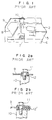
- a conventional totally enclosed fan-cooled rotary motor has the following construction.
- a stator comprising a stator core 2 and a stator coil 3 wound thereon is disposed within a stator frame 1 and is positioned between the inner periphery of the frame 1 and a rotor 5.
- the rotor 5 is disposed inward of the stator and is fixed to a rotary shaft 6.
- An end bracket 4 is fixed to one end of the stator frame 1.
- the rotary shaft 6 is rotatably supported by a bearing 7 which is in turn supported by the bracket 4.
- One end of the rotary shaft 6 extends through the end bracket 4, and a fan 8 is mounted to this shaft end.
- a fan cover 9 covering the fan 8 is fixed by bolts 11 to projection seats 10 provided on the end bracket 4.
- the above-described construction entails the following problem.
- the fan cover 9 may resonate, generating large, unpleasant sound, when it is influenced by, e.g., incorrect balance of the rotor 5, electromagnetic vibration of the motor which includes high-frequency vibration when an inverter is driven, or gear meshing vibration of a geared motor.
- the restraining means (1) is expensive because it employs as the damping material, a special material.
- the restraining means (2) requires a long assembly time because the rubber vibration insulators must completely separate the fan cover from the projection seats. If the cover and the seats should be brought into mutual contact through the bolts, the vibration restraining effect will be spoiled.
- An object of the present invention is to provide a low-cost, low-noise rotary machine of which the fan cover is restrained from vibration to reduce the level of noise produced by the rotary machine during operation, while enabling improved efficiency of cover assembly operation.
- a rotary machine comprising a machine body having an opening; a cover covering the opening of the body; and a means for fixing the cover to the machine body; the means for fixing comprising: a plurality of mounting portions provided on the machine body at the end adjacent to the cover; and a peripheral edge of the cover which is adjacent to the machine body, CHARACTERISED BY said means for fixing further comprising a plurality of plate spring-shaped mounting brackets provided on the peripheral edge, with their distal end portions projecting therefrom; and rubber vibration insulating members in said mounting portions through which the distal ends are inserted, and by the mounting portions being a plurality of grooves or holes into which the distal end portions of the brackets are inserted.
- the cover is mounted by the structure where the mounting brackets are inserted into the mounting portions through the rubber vibration insulating members, the rubber vibration insulating members securely insulate the cover from vibration of the machine body, thereby suppressing the level of noise produced by the machine during operation.
- the position of the cover can be easily determined, thereby improving the efficiency at which the cover is assembled.
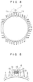
- a plurality of cooling fins are formed on the outer periphery of the stator frame 1, and they extend longitudinally of the frame 1.
- a plurality of fin pairs are each formed by two adjacent fins 1a which face each other.
- Longitudinal recesses 1b are formed on the mutually facing side surfaces of the fins 1a so that the recessed surfaces of the paired fins 1a define a plurality of paired longitudinal grooves.
- a lifting lug (not shown) is engaged with a pair of grooves and is slid along the pair of grooves and fixed at a position that balances the motor. The manner in which the lifting lug is engaged with the lifting lug mounting grooves is shown in Japanese Utility Model Application No. 63-141954,-JP-U-2-650 58
- the fan cover 9 has a peripheral edge on the side of which the cover 9 is mounted to the machine body.
- a plurality of plate-spring-shaped brackets 13 are provided on the peripheral edge, with their distal end portions projecting therefrom.
- the lifting lug mounting grooves defined by the mutually facing surfaces of paired cooling fins 1a serve as cover mounting portions of the cover fixing means.
- a plurality of rubber vibration insulating members 14 have a dimension slightly larger than the size of the space between the mutually facing recesses 1b. Each rubber member 14 has a through hole extending longitudinally thereof. The rubber vibration insulating members 14 are already fitted into the inter-fin grooves.
- the distal end portions of the plate-spring-shaped brackets 13 of the cover 9 are inserted through the through holes of the rubber members 14, whereby the fan cover 9 is mounted and fixed to the machine body.
- the above-described cover fixing structure has the following advantages.
- the fan cover 9 can be easily mounted, thereby improving the efficiency of cover assembly operation. Since the rubber vibration insulating members 14 are interposed, the fan cover 9 is insulated from the stator frame 1, thereby suppressing vibration of the cover 9, hence, reducing the level of noise produced by the totally enclosed fan-cooled rotary motor during operation.
- the cover fixing structure is such that the rubber vibration insulating members 14 are already fitted into the lifting lug mounting grooves, and, during cover assembly, the mounting brackets 13 are inserted through the rubber members 14 to fix the cover 9 in place.
- the structure may alternatively be such that the brackets 13 are already inserted into and fixed to the rubber members 14. In this case, the brackets 13 and the rubber members 14 can be simultaneously mounted or dismounted.
- lifting lug mounting grooves are used as the portions for mounting the fan cover 9, this is a mere example.
- grooves for mounting a housing cover covering the entire machine may be used.
- cover mounting portions such as grooves or holes may, of course, be provided separately.
- the description given above concerns the mounting of a fan cover of a totally enclosed fan-cooled rotary motor, this is a mere example.
- the application of the present invention is not limited to the above-described mounting operation, and the present invention is applicable to the mounting of a cover of a rotary machine in general.
- the present invention may advantageously be applied as a method of mounting a fan cover of a reduction gear system, or a method of mounting an air deflector of an open, drip-proof rotary motor.
- the present invention having the above-described construction provides the following advantageous effects.
- a cover of a rotary machine is mounted to the machine body by a mounting means in such a manner that the cover is completely insulated from the machine body by a rubber vibration insulator. Therefore, vibration transmitted from various mechanism inside the rotary machine is absorbed by the rubber insulator so that substantially no vibration is transmitted to the cover of the rotary machine. As a result, the level of noise produced by the entire machine is lowered.
- the mounting means has a simple structure, the machine can be manufactured at low cost.
- the position of the cover can be easily determined, thereby facilitating the cover assembly operation, hence, improving the efficiency of assembly operation.
Landscapes
- Engineering & Computer Science (AREA)
- Power Engineering (AREA)
- Motor Or Generator Frames (AREA)
- Motor Or Generator Cooling System (AREA)
Claims (2)
- Machine rotative comportant:
un corps (1) de machine ayant une ouverture;
un couvercle (9) recouvrant ladite ouverture dudit corps, et
des moyens de fixation du couvercle (9) sur le corps (1) de la machine; des moyens de fixation comportant plusieurs parties (1b) de montage agencées sur ledit corps (1) de la machine au niveau de l'extrémité contiguë audit couvercle (9); et un bord périphérique dudit couvercle (9) qui est contiguë audit corps (1) de la machine, caractérisée en ce que lesdits moyens de fixation comportent en outre plusieurs étriers (13) de montage en forme de ressort plat agencés sur ledit bord périphérique, leurs parties formant extrémité distale faisant saillie à partir de celui-ci; et des éléments en caoutchouc (14) isolant des vibrations situées dans lesdites parties de montage à travers lesquels les extrémités distales sont insérées, et en ce que lesdites parties (1b) de montage sont plusieurs gorges ou trous dans lesquels sont insérées lesdites parties formant extrémité distale desdits étriers (13). - Machine rotative selon la revendication 1, dans laquelle lesdites parties (1b) de montage dudit corps (1) de la machine comportent des gorges adaptées pour être en prise avec une patte de levage destinée à maintenir ledit corps (1) de la machine en place.
Priority Applications (2)
| Application Number | Priority Date | Filing Date | Title |
|---|---|---|---|
| EP19900110718 EP0460258B1 (fr) | 1990-06-06 | 1990-06-06 | Machine rotative |
| DE69013338T DE69013338T2 (de) | 1990-06-06 | 1990-06-06 | Rotierende Maschine. |
Applications Claiming Priority (1)
| Application Number | Priority Date | Filing Date | Title |
|---|---|---|---|
| EP19900110718 EP0460258B1 (fr) | 1990-06-06 | 1990-06-06 | Machine rotative |
Publications (2)
| Publication Number | Publication Date |
|---|---|
| EP0460258A1 EP0460258A1 (fr) | 1991-12-11 |
| EP0460258B1 true EP0460258B1 (fr) | 1994-10-12 |
Family
ID=8204060
Family Applications (1)
| Application Number | Title | Priority Date | Filing Date |
|---|---|---|---|
| EP19900110718 Expired - Lifetime EP0460258B1 (fr) | 1990-06-06 | 1990-06-06 | Machine rotative |
Country Status (2)
| Country | Link |
|---|---|
| EP (1) | EP0460258B1 (fr) |
| DE (1) | DE69013338T2 (fr) |
Family Cites Families (2)
| Publication number | Priority date | Publication date | Assignee | Title |
|---|---|---|---|---|
| DE3347555C2 (de) * | 1983-12-30 | 1987-04-30 | Siemens AG, 1000 Berlin und 8000 München | Wärmetauscher |
| DE3641096A1 (de) * | 1986-01-10 | 1987-07-16 | Siemens Ag | Elektrische maschine mit einer deren aussenluefter abdeckenden topffoermigen luefterhaube |
-
1990
- 1990-06-06 EP EP19900110718 patent/EP0460258B1/fr not_active Expired - Lifetime
- 1990-06-06 DE DE69013338T patent/DE69013338T2/de not_active Expired - Fee Related
Also Published As
| Publication number | Publication date |
|---|---|
| DE69013338D1 (de) | 1994-11-17 |
| DE69013338T2 (de) | 1995-04-06 |
| EP0460258A1 (fr) | 1991-12-11 |
Similar Documents
| Publication | Publication Date | Title |
|---|---|---|
| US5026476A (en) | Antivibration cover for rotary machine | |
| US5051636A (en) | Dynamic electric machine | |
| EP3068018B1 (fr) | Moteur à rotor externe | |
| US20180226857A1 (en) | Air-conditioning blower motor unit | |
| JPH04289757A (ja) | 軸方向長さを短縮したフラットモータ | |
| US4028568A (en) | AC Generator for vehicles | |
| JP2931865B2 (ja) | モータ内蔵形アクチュエータ | |
| EP0460258B1 (fr) | Machine rotative | |
| EP0633647B1 (fr) | Moteur électrique moulé en résine avec un amortisseur de vibrations en caoutchouc | |
| US3043970A (en) | Motor support and vibration isolation means | |
| US5801468A (en) | Rear bearing creep prevention apparatus for vehicle AC generator | |
| JP6589136B2 (ja) | 電動送風機及びそれを備えた電気掃除機 | |
| KR920001212B1 (ko) | 동축형 스타터장치 | |
| KR200160582Y1 (ko) | 모터 하우징 | |
| US5059843A (en) | Locking end cover for rotary machine | |
| JP2896059B2 (ja) | アウターロータ型ブラシレスdcモータ | |
| CN217824524U (zh) | 电梯门电机及其电梯 | |
| JPH10271720A (ja) | モールドモータの固定子 | |
| KR20000009906A (ko) | 전동기 | |
| JP4310117B2 (ja) | 動力機械の駆動用モータの防音構造 | |
| JPH11234955A (ja) | 回転電機 | |
| KR0112396Y1 (ko) | 냉각팬용 모터 하우징의 구조 | |
| KR900005026Y1 (ko) | 축류 팬 | |
| EP0334150B1 (fr) | Moteur commutateur électrique, en particulier pour machines à laver domestiques | |
| JP2025064446A (ja) | モータ装置およびその製造方法 |
Legal Events
| Date | Code | Title | Description |
|---|---|---|---|
| PUAI | Public reference made under article 153(3) epc to a published international application that has entered the european phase |
Free format text: ORIGINAL CODE: 0009012 |
|
| AK | Designated contracting states |
Kind code of ref document: A1 Designated state(s): AT CH DE FR GB IT LI SE |
|
| 17P | Request for examination filed |
Effective date: 19920214 |
|
| 17Q | First examination report despatched |
Effective date: 19930727 |
|
| RBV | Designated contracting states (corrected) |
Designated state(s): DE FR GB IT |
|
| GRAA | (expected) grant |
Free format text: ORIGINAL CODE: 0009210 |
|
| AK | Designated contracting states |
Kind code of ref document: B1 Designated state(s): DE FR GB IT |
|
| ITF | It: translation for a ep patent filed | ||
| REF | Corresponds to: |
Ref document number: 69013338 Country of ref document: DE Date of ref document: 19941117 |
|
| ET | Fr: translation filed | ||
| PLBE | No opposition filed within time limit |
Free format text: ORIGINAL CODE: 0009261 |
|
| STAA | Information on the status of an ep patent application or granted ep patent |
Free format text: STATUS: NO OPPOSITION FILED WITHIN TIME LIMIT |
|
| 26N | No opposition filed | ||
| REG | Reference to a national code |
Ref country code: GB Ref legal event code: IF02 |
|
| PGFP | Annual fee paid to national office [announced via postgrant information from national office to epo] |
Ref country code: GB Payment date: 20020605 Year of fee payment: 13 |
|
| PGFP | Annual fee paid to national office [announced via postgrant information from national office to epo] |
Ref country code: FR Payment date: 20020610 Year of fee payment: 13 |
|
| PGFP | Annual fee paid to national office [announced via postgrant information from national office to epo] |
Ref country code: DE Payment date: 20020612 Year of fee payment: 13 |
|
| PG25 | Lapsed in a contracting state [announced via postgrant information from national office to epo] |
Ref country code: GB Free format text: LAPSE BECAUSE OF NON-PAYMENT OF DUE FEES Effective date: 20030606 |
|
| PG25 | Lapsed in a contracting state [announced via postgrant information from national office to epo] |
Ref country code: DE Free format text: LAPSE BECAUSE OF NON-PAYMENT OF DUE FEES Effective date: 20040101 |
|
| GBPC | Gb: european patent ceased through non-payment of renewal fee |
Effective date: 20030606 |
|
| PG25 | Lapsed in a contracting state [announced via postgrant information from national office to epo] |
Ref country code: FR Free format text: LAPSE BECAUSE OF NON-PAYMENT OF DUE FEES Effective date: 20040227 |
|
| REG | Reference to a national code |
Ref country code: FR Ref legal event code: ST |
|
| PG25 | Lapsed in a contracting state [announced via postgrant information from national office to epo] |
Ref country code: IT Free format text: LAPSE BECAUSE OF NON-PAYMENT OF DUE FEES;WARNING: LAPSES OF ITALIAN PATENTS WITH EFFECTIVE DATE BEFORE 2007 MAY HAVE OCCURRED AT ANY TIME BEFORE 2007. THE CORRECT EFFECTIVE DATE MAY BE DIFFERENT FROM THE ONE RECORDED. Effective date: 20050606 |