EP0460441B1 - Verfahren zur Qualitätsbestimmung einer Quetschverbindung - Google Patents
Verfahren zur Qualitätsbestimmung einer Quetschverbindung Download PDFInfo
- Publication number
- EP0460441B1 EP0460441B1 EP91108058A EP91108058A EP0460441B1 EP 0460441 B1 EP0460441 B1 EP 0460441B1 EP 91108058 A EP91108058 A EP 91108058A EP 91108058 A EP91108058 A EP 91108058A EP 0460441 B1 EP0460441 B1 EP 0460441B1
- Authority
- EP
- European Patent Office
- Prior art keywords
- data element
- element pairs
- terminal
- force
- pairs
- Prior art date
- Legal status (The legal status is an assumption and is not a legal conclusion. Google has not performed a legal analysis and makes no representation as to the accuracy of the status listed.)
- Expired - Lifetime
Links
- 238000000034 method Methods 0.000 title claims description 23
- 238000002788 crimping Methods 0.000 claims description 32
- 230000033001 locomotion Effects 0.000 claims description 7
- 230000013011 mating Effects 0.000 claims description 6
- FGUUSXIOTUKUDN-IBGZPJMESA-N C1(=CC=CC=C1)N1C2=C(NC([C@H](C1)NC=1OC(=NN=1)C1=CC=CC=C1)=O)C=CC=C2 Chemical compound C1(=CC=CC=C1)N1C2=C(NC([C@H](C1)NC=1OC(=NN=1)C1=CC=CC=C1)=O)C=CC=C2 FGUUSXIOTUKUDN-IBGZPJMESA-N 0.000 claims 2
- 238000009413 insulation Methods 0.000 description 8
- 238000004519 manufacturing process Methods 0.000 description 5
- 230000007246 mechanism Effects 0.000 description 5
- 238000003860 storage Methods 0.000 description 5
- 238000006073 displacement reaction Methods 0.000 description 4
- 230000002950 deficient Effects 0.000 description 3
- 230000007547 defect Effects 0.000 description 2
- 230000000694 effects Effects 0.000 description 2
- 230000007613 environmental effect Effects 0.000 description 2
- 238000012360 testing method Methods 0.000 description 2
- 229930091051 Arenine Natural products 0.000 description 1
- 239000004593 Epoxy Substances 0.000 description 1
- 230000005355 Hall effect Effects 0.000 description 1
- 230000009471 action Effects 0.000 description 1
- 230000002411 adverse Effects 0.000 description 1
- 238000013459 approach Methods 0.000 description 1
- 230000008901 benefit Effects 0.000 description 1
- 238000004891 communication Methods 0.000 description 1
- 230000007812 deficiency Effects 0.000 description 1
- 230000001419 dependent effect Effects 0.000 description 1
- 230000001066 destructive effect Effects 0.000 description 1
- 238000010586 diagram Methods 0.000 description 1
- 238000007689 inspection Methods 0.000 description 1
- 239000000314 lubricant Substances 0.000 description 1
- 238000012544 monitoring process Methods 0.000 description 1
- 230000008569 process Effects 0.000 description 1
- 230000004044 response Effects 0.000 description 1
- 230000011664 signaling Effects 0.000 description 1
- 238000005476 soldering Methods 0.000 description 1
Images


Classifications
-
- H—ELECTRICITY
- H01—ELECTRIC ELEMENTS
- H01R—ELECTRICALLY-CONDUCTIVE CONNECTIONS; STRUCTURAL ASSOCIATIONS OF A PLURALITY OF MUTUALLY-INSULATED ELECTRICAL CONNECTING ELEMENTS; COUPLING DEVICES; CURRENT COLLECTORS
- H01R43/00—Apparatus or processes specially adapted for manufacturing, assembling, maintaining, or repairing of line connectors or current collectors or for joining electric conductors
- H01R43/04—Apparatus or processes specially adapted for manufacturing, assembling, maintaining, or repairing of line connectors or current collectors or for joining electric conductors for forming connections by deformation, e.g. crimping tool
-
- H—ELECTRICITY
- H01—ELECTRIC ELEMENTS
- H01R—ELECTRICALLY-CONDUCTIVE CONNECTIONS; STRUCTURAL ASSOCIATIONS OF A PLURALITY OF MUTUALLY-INSULATED ELECTRICAL CONNECTING ELEMENTS; COUPLING DEVICES; CURRENT COLLECTORS
- H01R43/00—Apparatus or processes specially adapted for manufacturing, assembling, maintaining, or repairing of line connectors or current collectors or for joining electric conductors
- H01R43/04—Apparatus or processes specially adapted for manufacturing, assembling, maintaining, or repairing of line connectors or current collectors or for joining electric conductors for forming connections by deformation, e.g. crimping tool
- H01R43/048—Crimping apparatus or processes
- H01R43/0486—Crimping apparatus or processes with force measuring means
-
- B—PERFORMING OPERATIONS; TRANSPORTING
- B30—PRESSES
- B30B—PRESSES IN GENERAL
- B30B15/00—Details of, or accessories for, presses; Auxiliary measures in connection with pressing
- B30B15/0094—Press load monitoring means
-
- B—PERFORMING OPERATIONS; TRANSPORTING
- B30—PRESSES
- B30B—PRESSES IN GENERAL
- B30B15/00—Details of, or accessories for, presses; Auxiliary measures in connection with pressing
- B30B15/14—Control arrangements for mechanically-driven presses
-
- Y—GENERAL TAGGING OF NEW TECHNOLOGICAL DEVELOPMENTS; GENERAL TAGGING OF CROSS-SECTIONAL TECHNOLOGIES SPANNING OVER SEVERAL SECTIONS OF THE IPC; TECHNICAL SUBJECTS COVERED BY FORMER USPC CROSS-REFERENCE ART COLLECTIONS [XRACs] AND DIGESTS
- Y10—TECHNICAL SUBJECTS COVERED BY FORMER USPC
- Y10T—TECHNICAL SUBJECTS COVERED BY FORMER US CLASSIFICATION
- Y10T29/00—Metal working
- Y10T29/49—Method of mechanical manufacture
- Y10T29/49002—Electrical device making
- Y10T29/49117—Conductor or circuit manufacturing
- Y10T29/49174—Assembling terminal to elongated conductor
- Y10T29/49181—Assembling terminal to elongated conductor by deforming
- Y10T29/49185—Assembling terminal to elongated conductor by deforming of terminal
-
- Y—GENERAL TAGGING OF NEW TECHNOLOGICAL DEVELOPMENTS; GENERAL TAGGING OF CROSS-SECTIONAL TECHNOLOGIES SPANNING OVER SEVERAL SECTIONS OF THE IPC; TECHNICAL SUBJECTS COVERED BY FORMER USPC CROSS-REFERENCE ART COLLECTIONS [XRACs] AND DIGESTS
- Y10—TECHNICAL SUBJECTS COVERED BY FORMER USPC
- Y10T—TECHNICAL SUBJECTS COVERED BY FORMER US CLASSIFICATION
- Y10T29/00—Metal working
- Y10T29/53—Means to assemble or disassemble
- Y10T29/53022—Means to assemble or disassemble with means to test work or product
-
- Y—GENERAL TAGGING OF NEW TECHNOLOGICAL DEVELOPMENTS; GENERAL TAGGING OF CROSS-SECTIONAL TECHNOLOGIES SPANNING OVER SEVERAL SECTIONS OF THE IPC; TECHNICAL SUBJECTS COVERED BY FORMER USPC CROSS-REFERENCE ART COLLECTIONS [XRACs] AND DIGESTS
- Y10—TECHNICAL SUBJECTS COVERED BY FORMER USPC
- Y10T—TECHNICAL SUBJECTS COVERED BY FORMER US CLASSIFICATION
- Y10T29/00—Metal working
- Y10T29/53—Means to assemble or disassemble
- Y10T29/5313—Means to assemble electrical device
- Y10T29/532—Conductor
- Y10T29/53209—Terminal or connector
- Y10T29/53213—Assembled to wire-type conductor
-
- Y—GENERAL TAGGING OF NEW TECHNOLOGICAL DEVELOPMENTS; GENERAL TAGGING OF CROSS-SECTIONAL TECHNOLOGIES SPANNING OVER SEVERAL SECTIONS OF THE IPC; TECHNICAL SUBJECTS COVERED BY FORMER USPC CROSS-REFERENCE ART COLLECTIONS [XRACs] AND DIGESTS
- Y10—TECHNICAL SUBJECTS COVERED BY FORMER USPC
- Y10T—TECHNICAL SUBJECTS COVERED BY FORMER US CLASSIFICATION
- Y10T29/00—Metal working
- Y10T29/53—Means to assemble or disassemble
- Y10T29/5313—Means to assemble electrical device
- Y10T29/532—Conductor
- Y10T29/53209—Terminal or connector
- Y10T29/53213—Assembled to wire-type conductor
- Y10T29/53235—Means to fasten by deformation
Definitions
- This invention relates to the termination of terminals to respective wires and to the controlling of the quality of such terminations.
- this invention relates to a method of determining the quality of the crimp of an electrical terminal crimped onto a wire.
- Terminals are typically crimped onto wires by means of a conventional crimping press having an anvil for supporting the electrical terminal and a die that is movable toward and away from the anvil for effecting the crimp.
- a terminal is placed on the anvil, an end of a wire is inserted into the ferrule or barrel of the terminal, and the die is caused to move toward the anvil to the limit of the stroke of the press, thereby crimping the terminal onto the wire.
- the die is then retracted to its starting point.
- the crimp height of a terminal is a measure of height or maximum vertical dimension of a given portion of the terminal after crimping. Ordinarily, if a terminal is not crimped to the correct crimp height for the particular terminal and wire combination, an unsatisfactory crimped connection will result. On the other hand many unsatisfactory crimped connections will, nevertheless, exhibit a "correct" crimp height.
- a crimp height variance or other physical variation in the crimped terminal is not in and of itself the cause of a defective crimp connection, but rather, is indicative of another factor which causes the poor connection.
- Such factors include using the wrong terminal or wire size, missing strands of wire, wrong wire type, and incorrect stripping of insulation. Since such defective crimped connections frequently have the appearance of high quality crimped connections, it is difficult to identify these defects so that timely corrective action may be taken.
- the present invention is related to a method for determining the quality of the crimp of an electrical terminal crimped onto a wire.
- the amount of deformation of the terminal is measured along with the corresponding amount of force required to effect the deformation for several different amounts of deformation thereby defining a plurality of measured force and deformation data element pairs having a force value and a terminal deformation value.
- a plurality of standard data element pairs are provided which correspond to a known quality of crimp. Selected ones of the measured data element pairs are related to corresponding ones of the plurality of standard data element pairs, thereby determining the quality of crimp of the crimped terminal.
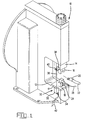
- a crimping press 10 having a base 12 and a ram 14 arranged for reciprocating opposed motion relative to the base 12.
- the crimping press 10 in the present example, is the type having a flywheel and clutch arrangement for imparting the reciprocating motion to the ram 14, however, other types of presses having a suitable ram stroke may be used in the practice of the present invention.
- the base 12 and ram 14 each carry a mating half of a crimping die set in the usual manner.
- the die set includes an anvil 16 which is removably attached to a base plate 17 and a punch 18 which is removably attached to the ram 14, as shown in Figure 1.
- the base plate 17 is coupled to the base 12 in a manner that will permit vertical movement of the plate 17.
- a typical terminal 20 is shown, in Figure 1, crimped onto a wire.
- a strain gage 24 is attached to the anvil 16 in the usual manner by epoxy or soldering.
- a pair of leads 26 carry a signal that is proportional to the stress placed on the anvil 16 which is transferred from the ram 14, through the terminal 20 and wires 22 being crimped, to the anvil 16.
- the signal appearing on the leads 26 is indicative of the force imposed upon the terminal 20 during crimping, as set forth in more detail in the aforementioned '186 patent.
- a linear distance sensor 30 is arranged to measure displacement of the ram 14 with respect to the base 12.
- the sensor 30 includes a stator 32, which is rigidly attached to the base 12 by a suitable bracket 34, and an armature which is movable within the stator in the vertical direction as viewed in Figure 1.
- a push rod 36 projects upwardly from the stator 32 and has one end attached to the movable armature and the other end adjustably attached to the ram 14 by means of a suitable bracket 38 and adjusting nut 40.
- a pair of leads 42 carry a signal that is proportional to the vertical position of the armature within the stator. This signal is indicative of the vertical distance between the anvil 16 and the punch 18 as set forth in more detail in the '186 patent.
- the actual crimp height of the crimped terminal 20 can be accurately determined. It will be understood that the signal on the lead 42 is also indicative of the amount of deformation of the terminal being crimped by the anvil 16 and punch 18. Additionally, other parameters may be determined as well, such as peak force exerted on the terminal 20 and the amount of work performed to complete the crimp.
- the method and apparatus for measuring force and ram displacement and generating their respective signals on the leads 26 and 42, as described above, is by way of example only. Any suitable devices that are well known in the art may be utilized for these functions. For example, permanent magnets may be associated with the ram and a hall effect device attached to the base and arranged to sense the relative position of the magnets in place of the sensor 30. Other suitable devices for sensing and signaling force ram displacement will occur to those skilled in the art and may be advantageously applied to practice the teachings of the present invention.
- wire crimping mechanism is identified as 16, 18 and 17 which represent the anvil, punch and movable base plate respectively
- force and ram position sensors are identified as 24 and 30 which represent the strain gage and linear distance sensor respectively.
- An insulation crimping mechanism 50 is depicted in Figure 2 as an example of other instrumentalities that may be controlled in a manner similar to that of the wire crimping mechanism. Other similar instrumentalities may also be controlled in a similar way.
- the actual adjusting means which physically moves or adjusts the base plate 17, in the case of the wire crimp mechanism, or another adjustable device in the case of the insulation crimp mechanism, are driven by stepper motors 52 and 54 respectively.
- a computer 56 having a storage device 58 associated therewith for storing a data base and an input/output device 60 for operator communication, is arranged to drive the stepper motors 52 and 54. This is done in response to operator input through the device 60 and input from either the force sensor 24 or the ram position sensor 30.
- the signal appearing on the leads 26, which is indicative of the force imposed upon the terminal, and the signal appearing on the leads 42, which is indicative of the relative position of the mating halves of the crimping die set 16 and 18, are monitored by the computer 56 and recorded on the storage device 58 in a manner that is well known in the art. These signals are recorded as pairs of data elements, one pair for each discrete increment of time during the crimping cycle, a rate of 4000 samples per second, for example, was successfully utilized in a test case of 90 crimped terminals of known quality, see Table 1.
- the samples may be taken based upon incremental changes in the values of either relative position or force instead of increments of time. The important consideration is that a sufficient number of samples are obtained to adequately define the work curve 100.
- Figure 4 shows several curves, which were plotted from various sets of data element pairs of selected test sample terminations to illustrate the effects of missing strands and of insulation included in the crimped connection.
- the first group of curves indicated at 70 represents crimped connections of known high quality.
- the second group of curves indicated at 72 represents a crimped connections having four missing strands from a 41 strand wire, and the third group of curves indicated at 74 represents crimped connections having portions of insulation within the crimped connection.
- the reason that the curves 74 have such a low peak force is that the insulation serves as a lubricant, causing individual strands of wire to break and slip out of the terminal being crimped.
- the curve 100 is a plot of a set of data element pairs which, hypothetically, represent the work curve of the crimping operation of a typical crimped terminal.
- the portion 102 of the curve between the points E1 and E2 on the position axis, represent the forces resulting from the punch 18 of the mating die halves engaging the terminal 20 and beginning to deform it. Beyond the point E2 until the point E3, the actual crimping of the terminal 20 takes place and is represented by the portion 104 of the curve.
- the force reaches its peak at E3 where the punch 18 begins to disengage by withdrawing from the anvil 16. This disengagement, which is represented by the portion 106 of the curve, continues from the point E3 to the point E4 where the force has receded to substantially zero.
- No data element pairs need be collected as the punch 18 approaches the point E1 and recedes from the point E4 since no work is performed on the terminal 20 during these movements of the punch.
- the portion of the curve 102 that is most significant in indicating defects in the crimped connection such as, for example, missing strands or wrong size of wire or terminal is the portion 104.
- the portion 104 shows a relatively sharp and somewhat linear increase in force.
- a group of data element pairs are selected from those that define the portion 104 having a force value between about 35 to 40 percent and about 90 to 95 percent of the peak force at the position E3. These force value percentage limits are not critical as long as the group of selected data elements does not include either of two portions 110 of the curve 102 that deviate significantly from the general linearity of the portion 104.
- This group of data element pairs is analyzed and compared to a standard group of pairs taken during a known high quality crimp cycle to determine the quality of the present crimped connection.
- the point 108 on the line that corresponds to a force value equal to about the average of the minimum and maximum values of the force data elements in the group is found. This is indicated as the 65 percent point along the force axis.
- the corresponding point along the position axis is then found and indicated as P on the position axis. It is this point P that can be compared to a similarly found, but statistically evolved, point P' of a number of known high quality terminations and a valid judgement made as to the quality of the crimp represented by the point P.
- the point P' may be determined by preparing a suitable number of correctly stripped wires and associated terminals to be crimped thereto. Each wire and corresponding terminal is placed, in turn, in crimping position within the press 10 and crimped while recording the data element pairs representing the work curve resulting in a set of standard force and position data element pairs. The position P is then calculated as set forth above in the description of Figure 3. After each such crimp operation, the crimped connection is manually examined for quality of crimp. In the event that the crimped connection is not of high quality, the corresponding data element pairs are purged from the memory device 58. When a suitable number of high quality crimped connections are formed, five in the present example, the mean P' of the five P value and the standard deviation are calculated.
- the machine 10 is calibrated by determining the mean P', as set forth above, and storing it along with the calculated standard deviation in the storage device 58. Thereafter, every production crimp cycle will be compared to this stored standard of known high quality to determine the quality of the production termination.
- the signals appearing on the leads 26 and 42 are recorded as measured data element pairs on the storage device 58.
- a group of measured data element pairs is selected from those that define the portion 104 of the curve 102 and have a force value of between about 35 percent and about 95 percent of the peak force F at the position E3.
- a straight line is fitted to the group of measured pairs and the point P is determined in a manner set forth above.
- This point P is compared with the calculated mean P' and a reject signal is generated by the computer 56 and displayed on the input/output device 60 if the point P is not within a predetermined number of standard deviations of the mean P'. In the present example three standard deviations were used. If the point P is within this limit the corresponding crimped connection is considered to be of acceptable quality.
- the group of measured data element pairs may be factored into the calculated mean P' and associated standard deviation so that subsequent comparisons will involve the new mean P'.
- This is useful where the machine 10 will be subject to slowly changing environmental conditions, such as temperature changes, or other changing conditions over a relatively long period of operation. Under such changing conditions the calibration must be continually updated to remain valid.
- the factoring of the group of measured data element pairs into the calculated mean P' can be effected in any suitable manner such as by including the group of measured pairs as a set with the sets of standard force and position data element pairs previously used to calculate the mean P' and standard deviation and these variables recalculated.
- a mean F' and standard deviation of the peak force is calculated for the set of known high quality terminations that were used to calculate the mean P' and stored on the storage device 58 during calibration of the machine 10, as set forth above.
- the peak force F at the position E3 of the curve 102 is also selected and compared with the calculated mean F' and a reject signal generated by the computer 56 and displayed on the input/output device 60 if the force F is not within a specified interval of the mean F'.
- 3 standard deviations of F' was used, however, other intervals may be useful for detecting specific deficiencies such as insulation within the crimped connection.
- the group of measured data element pairs may be factored into the calculation of the mean P' if no reject signal is generated.
- the measured force F may also be factored into the mean F' thereby accounting for slowly changing environmental conditions over a relatively long period of operation.
- An important advantage of the present invention is the capability to detect missing strands from a crimped connection or the inclusion of insulation therein immediately after the crimping cycle is completed and a reject signal automatically generated prior to the next crimping operation.
- This capability may be integrated into an automated machine where each crimped connection is evaluated for quality of crimp and those that do not meet the standard can be automatically discarded. This can be done during production without adversely affecting the running speed of the machine.
Landscapes
- Engineering & Computer Science (AREA)
- Mechanical Engineering (AREA)
- Manufacturing & Machinery (AREA)
- Manufacturing Of Electrical Connectors (AREA)
- Agricultural Machines (AREA)
Claims (7)
- Verfahren zum Bestimmen der Qualität der Crimpverbindung eines elektrischen Anschlusses (20), der unter Verwendung einer Crimpvorrichtung auf einen Draht (22) gecrimpt ist, die eine Presse (10) mit einer Basis (12) und einer Ramme (14) beinhaltet, die einander gegenüberliegend, relativ zueinander hin- und herbewegbar sind, wobei die Basis (12) und die Ramme (14) jeweils eine komplementäre Hälfte eines Crimpwerkzeugsatzes (14, 18) tragen, wobei das Verfahren folgende Schritte aufweist:a) Plazieren des Anschlusses (20) und des Drahtes (22) in Crimpposition innerhalb der Crimpvorrichtung;b) Veranlassen der Basis (12) und/oder der Ramme (14) zur Ausführung einer Relativbewegung, so daß der Werkzeugsatz (14, 18) an dem Anschluß (20) angreift, diesen auf den Draht (22) crimpt sowie sich von diesem trennt;c) während des Angreifens, Crimpens und Trennens gemäß dem Schritt b) erfolgendes, gleichzeitiges Messen sowohl der Distanz zwischen den Anschlußangreifbereichen des Werkzeugsatzes (14, 18) als auch der durch den Werkzeugsatz (14, 18) auf den Anschluß (20) ausgeübten Kraft für eine Anzahl verschiedener Relativpositionen der komplementären Hälften des Werkzeugsatzes (14, 18), um dadurch eine Anzahl gemessener Kraft- und Positions-Datenelementpaaren zu schaffen, die einen Kraftwert bzw. einen Positionswert aufweisen; d) Schaffen einer Anzahl von Standard-Datenelementpaaren, die einer bekannten Crimpqualität entsprechen; unde) in Beziehung Setzen von ausgewählten der mehreren gemessenen Datenelementpaare zu entsprechenden der mehreren Standard-Datenelementpaare, um dadurch die Qualität der Crimpverbindung des gecrimpten Anschlusses (20) zu bestimmen;
wobei die ausgewählten der Anzahl der gemessenen Datenelementpaare gemäß Schritt e) eine erste Gruppe der Paare beinhaltet, die nur während des Angreifens und Crimpens gemäß Schritt c) definiert werden und einen Kraftwert zwischen ca. 35 % und ca. 95 % der maximal gemessenen Kraft der Anzahl von Datenelementpaaren aufweisen,
wobei das in Beziehung Setzen gemäß Schritt e) folgende Schritte beinhaltet:e1) Ausführen einer nach dem Verfahren der kleinsten Quadrate erfolgenden Anpassung der ersten Gruppe von Datenelementpaaren an eine gerade Linie (106);e2) Berechnen einer Position P, die einem Punkt auf der geraden Linie entspricht, der einen Kraftwert F besitzt, der in etwa dem Mittel aus der maximalen und der minimalen gemessenen Kraft entspricht; unde3) Vergleichen der berechneten Position P des Schrittes (e2) mit dem Positionswert eines entsprechenden Datenelementpaares der Anzahl der Standard-Datenelementpaare mit einem Kraftwert, der im wesentlichen F entspricht. - Verfahren nach Anspruch 1, wobei die Schaffung einer Anzahl von Standard-Datenelementpaaren gemäß Schritt d) folgende Schritte beinhaltet:d1) Bereitstellen eines bekannten guten Anschlusses (20) und eines korrekt abisolierten Drahtes (22) und Plazieren des Anschlusses und des Drahtes in Crimpposition innerhalb der Crimpvorrichtung;d2) Veranlassen der Basis (12) und/oder der Ramme (14) zur Ausführung einer Relativbewegung, so daß der Werkzeugsatz (14, 18) an dem Anschluß (20) angreift, diesen auf den Draht (22) crimpt und sich von diesem trennt;d3) während des Angreifens, Crimpens und Trennens gemäß Schritt d2) erfolgendes gleichzeitiges Bestimmen sowohl der Distanz zwischen den Anschlußangreifbereichen des Werkzeugsatzes (14, 18) als auch der durch den Werkzeugsatz (14, 18) auf den Anschluß (20) ausgeübten Kraft für eine Anzahl verschiedener Relativpositionen der komplementären Hälften des Werkzeugsatzes, um dadurch eine Anzahl von Standardkraft- und Standardpositions-Datenelementpaaren zu schaffen;d4) Wiederholen der Schritte d1), d2) und d3) wenigstens einmal, um dadurch ein Muster aus wenigstens zwei Sätzen der Standardkraft- und Standartpositions-Datenelementpaare zu definieren;d5) Auswählen einer Gruppe einander benachbarter Paare aus jedem solchen Satz;d6) Ausführung einer nach dem Verfahren der kleinsten Quadrate erfolgenden Anpassung an eine gerade Linie (106) der Gruppe von Paaren für jeden Satz;d7) für jede gerade Linie (106) erfolgende Berechnung einer Position P, die einem Punkt auf der geraden Linie mit einem Kraftwert F entspricht, der in etwa dem Mittel aus der minimalen und der maximalen Kraft der Datenelementpaare in dem der geraden Linie (106) entsprechenden Satz entspricht;d8) Berechnen des Mittelwerts P' und der Standardabweichung der Positionen P für das Muster.
- Verfahren nach Anspruch 2,
wobei der Vergleichsschritt e3) das Vergleichen der berechneten Position P der gemessenen Datenelementpaare mit dem berechneten Mittelwert P' des Musters beinhaltet. - Verfahren nach Anspruch 3,
das folgenden Schritt beinhaltet:
f) Schaffen eines Ausschußsignals, wenn die berechnete Position P der gemessenen Datenelementpaare eine vorbestimmte Anzahl von Standartabweichungen von dem berechneten Mittelwert übersteigt. - Verfahren nach Anspruch 2, 3 oder 4, mit folgendem Schritt:
d7) Berechnen des Mittelwerts F' und der Standardabweichung der maximalen Kraftwerte für die Sätze der Datenelementpaare in dem Muster, und wobei der Vergleichsschritt e3) das Vergleichen der maximalen Kraft der gemessenen Datenelementpaare mit dem berechneten Mittelwert F' der maximalen Kraft des Musters beinhaltet. - Verfahren nach Anspruch 5,
wobei der Schritt f) die Schaffung eines Ausschußsignals beinhaltet, wenn die maximale Kraft der gemessenen Datenelementpaare eine vorbestimmte Anzahl von Standardabweichungen von dem berechneten Mittelwert F' der maximalen Kraft des Musters übersteigt. - Verfahren nach Anspruch 6,
mit folgendem Schritt:
g) wenn das Ausschußsignal gemäß Schritt f) nicht erzeugt wird erfolgende Neuberechnung des Mittelwerts P' und der Standardabweichung der Positionen P für das Muster, als ob das Muster die erste Gruppe der Paare gemäß Schritt e) als zusätzlichen Satz enthalten hätte.
Applications Claiming Priority (2)
| Application Number | Priority Date | Filing Date | Title |
|---|---|---|---|
| US529036 | 1990-05-29 | ||
| US07/529,036 US5197186A (en) | 1990-05-29 | 1990-05-29 | Method of determining the quality of a crimped electrical connection |
Publications (2)
| Publication Number | Publication Date |
|---|---|
| EP0460441A1 EP0460441A1 (de) | 1991-12-11 |
| EP0460441B1 true EP0460441B1 (de) | 1996-02-28 |
Family
ID=24108247
Family Applications (1)
| Application Number | Title | Priority Date | Filing Date |
|---|---|---|---|
| EP91108058A Expired - Lifetime EP0460441B1 (de) | 1990-05-29 | 1991-05-17 | Verfahren zur Qualitätsbestimmung einer Quetschverbindung |
Country Status (8)
| Country | Link |
|---|---|
| US (1) | US5197186A (de) |
| EP (1) | EP0460441B1 (de) |
| JP (1) | JP3154740B2 (de) |
| KR (1) | KR100191695B1 (de) |
| CN (1) | CN1025393C (de) |
| AR (1) | AR246641A1 (de) |
| DE (1) | DE69117351T2 (de) |
| ES (1) | ES2084055T3 (de) |
Cited By (3)
| Publication number | Priority date | Publication date | Assignee | Title |
|---|---|---|---|---|
| RU2241284C2 (ru) * | 1999-01-26 | 2004-11-27 | Тайко Электроникс Ю-Кей Лимитид | Способ и устройство для обжатия композитных электрических изоляторов |
| US8671538B2 (en) | 2009-04-09 | 2014-03-18 | Schleuniger Holding Ag | Method of monitoring a crimping process, crimping press and computer program product |
| US8904616B2 (en) | 2009-04-09 | 2014-12-09 | Schleuniger Holding Ag | Method of monitoring a crimping process, crimping press and computer program product |
Families Citing this family (59)
| Publication number | Priority date | Publication date | Assignee | Title |
|---|---|---|---|---|
| GB9012058D0 (en) * | 1990-05-30 | 1990-07-18 | Amp Gmbh | Method of,and apparatus for,controlling the crimp height of crimped electrical connections |
| JP3042195B2 (ja) * | 1992-09-01 | 2000-05-15 | 住友電気工業株式会社 | 圧着端子の加工方法及びその装置 |
| JPH06267349A (ja) * | 1993-03-12 | 1994-09-22 | Sumitomo Wiring Syst Ltd | 平型多芯電線製造装置におけるテープ貼り位置制御方法およびテープ貼り位置制御装置 |
| US5502996A (en) * | 1994-12-12 | 1996-04-02 | The Whitaker Corporation | Crimping press actuator assembly |
| US5727409A (en) * | 1994-12-28 | 1998-03-17 | Yazaki Corporation | Method of controlling a terminal crimping apparatus |
| US5937505A (en) * | 1995-03-02 | 1999-08-17 | The Whitaker Corporation | Method of evaluating a crimped electrical connection |
| JPH103978A (ja) * | 1996-06-12 | 1998-01-06 | Yazaki Corp | 端子圧着装置の制御方法 |
| US5614109A (en) * | 1995-07-05 | 1997-03-25 | Cecil; Dimitrios G. | Welding line with quality control storage devices |
| DE19540709C1 (de) * | 1995-11-02 | 1997-01-09 | Freudenberg Carl Fa | Vorrichtung zur Herstellung einer Quetschverbindung zwischen einem plastisch verformbaren, metallischen Polschuh und einem Kabelende |
| JPH09330779A (ja) * | 1996-06-12 | 1997-12-22 | Yazaki Corp | 端子圧着装置の制御方法 |
| US5813274A (en) * | 1996-09-20 | 1998-09-29 | The Whitaker Corporation | Magnetic press |
| DE19738298C1 (de) | 1997-09-02 | 1999-04-08 | Poly Clip System Gmbh & Co Kg | Verfahren zum Einrichten einer Verschließmaschine und Vorrichtung zum Verschließen von Verschlußklammern |
| EP0943422B1 (de) * | 1998-03-16 | 2004-05-19 | Yamada Dobby Co., Ltd. | Steuervorrichtung für den Stössel einer Presse |
| DE29806179U1 (de) | 1998-04-03 | 1998-10-08 | Connectool GmbH & Co., 32758 Detmold | Crimpzange |
| DE19843156A1 (de) * | 1998-09-21 | 2000-04-20 | Sle Electronic Gmbh | Verfahren zur Qualitätssicherung von in einer Crimpvorrichtung hergestellten Crimpverbindungen sowie Crimpwerkzeug und Crimpvorrichtung |
| DE19935402C2 (de) * | 1999-07-30 | 2001-08-16 | Contitech Luftfedersyst Gmbh | Verfahren und Vorrichtung zur dichten Befestigung eines Schlauchstückes aus elastomerem Werkstoff an einem Anschlussteil |
| US6276052B1 (en) * | 1999-08-26 | 2001-08-21 | The Whitaker Corporation | Applicator seating sensor |
| US6505494B1 (en) * | 1999-09-17 | 2003-01-14 | Artos Engineering Company | Method of calibrating a crimping press |
| DE19960652C1 (de) * | 1999-12-16 | 2001-03-01 | Itt Mfg Enterprises Inc | Verfahren zum Verpressen einer Rohrleitung mit einem Schlauch oder einer Rohrleitung unter Zuhilfenahme einer Presshülse |
| JP2001267034A (ja) * | 2000-03-22 | 2001-09-28 | Yazaki Corp | 端子段取替装置 |
| US6487885B2 (en) * | 2000-10-30 | 2002-12-03 | Komax Holding Ag | Method and apparatus for producing a crimped connection |
| JP4031214B2 (ja) * | 2001-03-19 | 2008-01-09 | 矢崎総業株式会社 | 端子圧着状態判別方法 |
| US7324864B2 (en) | 2001-06-15 | 2008-01-29 | Smithkline Beecham Corporation | Apparatus and method for measuring forces imparted on valve assemblies of metered dose delivery containers during manufacture thereof |
| CN1297044C (zh) * | 2001-06-15 | 2007-01-24 | 矢崎总业株式会社 | 接线端压接状态的测试方法 |
| JP3935034B2 (ja) * | 2002-09-17 | 2007-06-20 | 矢崎総業株式会社 | 設計支援システム |
| DE102005025173C5 (de) * | 2005-06-01 | 2013-08-22 | Poly-Clip System Gmbh & Co Kg | Clipmaschine mit einem Verschließhebel |
| EP1757522B1 (de) * | 2005-08-26 | 2009-05-06 | Tipper Tie Alpina AG | Verfahren und Clipvorrichtung zum Verschliessen wurstförmiger Verpackungen |
| FR2916091B1 (fr) * | 2007-05-11 | 2009-07-17 | Eurocopter France | Amelioration aux systemes de sertissage a controle integre. |
| US8746026B2 (en) | 2008-10-02 | 2014-06-10 | Komax Holding Ag | Method for determining the quality of a crimped connection between a conductor and a contact |
| EP2414154B1 (de) * | 2009-04-02 | 2021-06-09 | Schleuniger AG | Crimppresse |
| US8224623B2 (en) * | 2010-04-09 | 2012-07-17 | Delphi Technologies, Inc. | Method to determine a quality acceptance criterion using force signatures |
| EP2378615A1 (de) * | 2010-04-13 | 2011-10-19 | Schleuniger Holding AG | Crimppresse |
| US9331447B2 (en) | 2010-12-07 | 2016-05-03 | Tyco Electronics Corporation | Crimping apparatus having a crimp quality monitoring system |
| US8671551B2 (en) | 2011-02-01 | 2014-03-18 | The United States Of America As Represented By The Administrator Of The National Aeronautics And Space Administration | Process for nondestructive evaluation of the quality of a crimped wire connector |
| DE102011004298A1 (de) * | 2011-02-17 | 2012-08-23 | Robert Bosch Gmbh | Verfahren und Vorrichtung zur qualitätssichernden Herstellung eine Crimpung |
| US8914961B2 (en) * | 2012-02-29 | 2014-12-23 | GM Global Technology Operations LLC | Methods and systems for measuring crimp quality |
| US9463556B2 (en) * | 2012-03-13 | 2016-10-11 | Hubbell Incorporated | Crimp tool force monitoring device |
| TWI608677B (zh) * | 2012-08-15 | 2017-12-11 | 威查格工具廠有限公司 | 壓接機用的變換承接器 |
| US9003645B1 (en) | 2013-01-17 | 2015-04-14 | The United States Of America As Represented By The Administrator Of The National Aeronautics And Space Administration | Ultrasonic device for assessing the quality of a wire crimp |
| US9391418B2 (en) | 2013-08-13 | 2016-07-12 | Tyco Electronics Corporation | Terminal crimping device for determining a crimp height of a crimped electrical connection |
| US9362700B2 (en) | 2013-08-13 | 2016-06-07 | Tyco Electronics Corporation | Device for determining a crimp height of a crimped electrical connection |
| US10090627B2 (en) | 2013-08-21 | 2018-10-02 | Te Connectivity Corporation | Filters for terminal crimping devices using ultrasonic signals |
| US10088455B2 (en) | 2014-06-04 | 2018-10-02 | Te Connectivity Corporation | Terminal crimping devices |
| US10153606B2 (en) | 2014-10-10 | 2018-12-11 | The United States Of America As Represented By The Administrator Of Nasa | Method to control crimping processes using ultrasonic transmission analysis |
| CN104897079B (zh) * | 2015-05-25 | 2017-09-29 | 杨志强 | 线束接插件视频检测方法及采用该方法的系统 |
| JP2017123385A (ja) * | 2016-01-06 | 2017-07-13 | 株式会社フジクラ | 蓄電デバイス及び蓄電モジュール |
| US10355437B2 (en) * | 2016-11-02 | 2019-07-16 | Te Connectivity Corporation | Terminal crimping machine including an electrical crimp consolidation circuit |
| US10522960B2 (en) | 2017-05-03 | 2019-12-31 | Te Connectivity Corporation | Crimp quality monitoring method and system for use with a hydraulic crimping apparatus |
| CN109655242A (zh) * | 2017-10-10 | 2019-04-19 | 中国商用飞机有限责任公司 | 用于检测线束与端接件的连接的可靠性的方法及设备 |
| WO2019152689A2 (en) | 2018-01-31 | 2019-08-08 | Abb Schweiz Ag | Crimping tool with wireless communication system |
| CA3097187C (en) * | 2018-04-23 | 2023-03-07 | Daniels Manufacturing Corporation | Programmable memory positioner and calibration system for a crimp tool and related methods |
| DE102019101016A1 (de) * | 2019-01-16 | 2020-07-16 | Harting Electric Gmbh & Co. Kg | Verfahren und Vorrichtung zur Überprüfung der Qualität einer Crimpung |
| CN110146439A (zh) * | 2019-04-26 | 2019-08-20 | 国网河北能源技术服务有限公司 | 一种电缆压接性能测试平台及其测试方法 |
| US11527860B2 (en) * | 2019-10-18 | 2022-12-13 | Tyco Electronics Uk Ltd. | Apparatus to determine quality of termination of wire using thermal characteristics |
| CN112531437B (zh) * | 2020-12-18 | 2022-07-15 | 陕西航空电气有限责任公司 | 一种冷拉梯形铜排工艺尺寸确定方法 |
| CN112946536B (zh) * | 2021-01-29 | 2022-12-27 | 广州国显科技有限公司 | 压接检测装置及检测方法 |
| CN115421082B (zh) * | 2022-09-01 | 2023-05-02 | 华能国际电力股份有限公司河北清洁能源分公司 | 一种金具与电缆导体压接状态测试装置及方法 |
| DE102022128652B4 (de) * | 2022-10-28 | 2026-03-19 | Tkr Spezialwerkzeuge Gmbh | Verfahren zur Überprüfung der Qualität einer Crimpverbindung sowie System hierzu |
| US12512639B2 (en) * | 2023-04-14 | 2025-12-30 | Te Connectivity Solutions Gmbh | System and method to determine quality of termination of wire using thermal characteristics |
Citations (1)
| Publication number | Priority date | Publication date | Assignee | Title |
|---|---|---|---|---|
| EP0367521A1 (de) * | 1988-11-04 | 1990-05-09 | The Whitaker Corporation | Bestimmung der Crimphöhe |
Family Cites Families (10)
| Publication number | Priority date | Publication date | Assignee | Title |
|---|---|---|---|---|
| US4294006A (en) * | 1979-10-18 | 1981-10-13 | General Electric Company | Automatic control for wire crimping machine |
| US4313258A (en) * | 1979-10-18 | 1982-02-02 | General Electric Company | Methods and apparatus for use in making electrical interconnections |
| FR2638296B1 (fr) * | 1988-10-25 | 1990-12-14 | Renault | Appareil de sertissage de connexions sur des fils electriques |
| DE3842009C1 (de) * | 1988-11-22 | 1990-03-22 | Kabelwerke Reinshagen Gmbh, 5600 Wuppertal, De | |
| DE4014221A1 (de) * | 1989-05-12 | 1990-11-15 | Siemens Ag | Verfahren und vorrichtung zur fertigungsueberwachung beim crimpen von flexiblen, abisolierten adern von leitungen |
| US4916810A (en) * | 1989-05-12 | 1990-04-17 | Amp Incorporated | Method and apparatus for terminating wires to terminals |
| JPH0759333B2 (ja) * | 1989-09-22 | 1995-06-28 | モレックス インコーポレーテッド | 圧着ツールの摩損を管理する圧着プレス及びその方法 |
| US5092026A (en) * | 1989-09-22 | 1992-03-03 | Molex Incorporated | Crimp height monitor |
| DE3942219C1 (en) * | 1989-12-21 | 1991-02-21 | Bernhard Dr.-Ing. 4782 Erwitte De Juergenhake | Crimped connection quality measurement method - measuring distance positionally fixed tool or press base and active tool or press head |
| DE4005399C1 (en) * | 1990-02-21 | 1991-04-11 | Bernhard Dr.-Ing. 4782 Erwitte De Juergenhake | Ensuring connection quality of crimped tags - comparing electrical connection with predetermined value and finishing processing only if within tolerance range |
-
1990
- 1990-05-29 US US07/529,036 patent/US5197186A/en not_active Expired - Lifetime
-
1991
- 1991-05-17 ES ES91108058T patent/ES2084055T3/es not_active Expired - Lifetime
- 1991-05-17 EP EP91108058A patent/EP0460441B1/de not_active Expired - Lifetime
- 1991-05-17 DE DE69117351T patent/DE69117351T2/de not_active Expired - Fee Related
- 1991-05-27 AR AR91319786A patent/AR246641A1/es active
- 1991-05-28 CN CN91103689A patent/CN1025393C/zh not_active Expired - Fee Related
- 1991-05-28 JP JP12338091A patent/JP3154740B2/ja not_active Expired - Fee Related
- 1991-05-28 KR KR1019910008701A patent/KR100191695B1/ko not_active Expired - Fee Related
Patent Citations (1)
| Publication number | Priority date | Publication date | Assignee | Title |
|---|---|---|---|---|
| EP0367521A1 (de) * | 1988-11-04 | 1990-05-09 | The Whitaker Corporation | Bestimmung der Crimphöhe |
Cited By (3)
| Publication number | Priority date | Publication date | Assignee | Title |
|---|---|---|---|---|
| RU2241284C2 (ru) * | 1999-01-26 | 2004-11-27 | Тайко Электроникс Ю-Кей Лимитид | Способ и устройство для обжатия композитных электрических изоляторов |
| US8671538B2 (en) | 2009-04-09 | 2014-03-18 | Schleuniger Holding Ag | Method of monitoring a crimping process, crimping press and computer program product |
| US8904616B2 (en) | 2009-04-09 | 2014-12-09 | Schleuniger Holding Ag | Method of monitoring a crimping process, crimping press and computer program product |
Also Published As
| Publication number | Publication date |
|---|---|
| JP3154740B2 (ja) | 2001-04-09 |
| ES2084055T3 (es) | 1996-05-01 |
| CN1056959A (zh) | 1991-12-11 |
| DE69117351T2 (de) | 1996-07-11 |
| EP0460441A1 (de) | 1991-12-11 |
| KR910020418A (ko) | 1991-12-20 |
| CN1025393C (zh) | 1994-07-06 |
| DE69117351D1 (de) | 1996-04-04 |
| US5197186A (en) | 1993-03-30 |
| KR100191695B1 (ko) | 1999-06-15 |
| JPH07111180A (ja) | 1995-04-25 |
| AR246641A1 (es) | 1994-08-31 |
Similar Documents
| Publication | Publication Date | Title |
|---|---|---|
| EP0460441B1 (de) | Verfahren zur Qualitätsbestimmung einer Quetschverbindung | |
| US5937505A (en) | Method of evaluating a crimped electrical connection | |
| EP0397434B1 (de) | Verfahren und Vorrichtung zur Verbindung eines Drahtes an einer Anschlussklemme | |
| US5123165A (en) | Method of determining the crimp height of a crimped electrical connection | |
| EP0367521B1 (de) | Bestimmung der Crimphöhe | |
| EP2649687B1 (de) | Crimpvorrichtung mit system zur überwachung der crimpqualität | |
| US4750131A (en) | Method of detecting faulty parts in a progressive die press | |
| US5092026A (en) | Crimp height monitor | |
| US8746026B2 (en) | Method for determining the quality of a crimped connection between a conductor and a contact | |
| EP1319450A1 (de) | Biegeverfahren und vorrichtung dafür | |
| EP0459476A2 (de) | Verfahren und Vorrichtung für die Einstellung der Crimphöhe einer gequetschten elektrischen Verbindung | |
| EP1071173B1 (de) | Anordnung und Verfahren zur Prüfung der Crimpqualität von Kontakten sowie Verfahren zur Besimmung des Reibungsverschleisses der Crimpmatritze | |
| US5275032A (en) | Method and apparatus for controlling the crimp height of crimped electrical connections | |
| US12199395B2 (en) | Method and device for monitoring the state of pressing elements of a crimping device | |
| WO2014010690A1 (ja) | 圧着端子のクリンプハイトの測定方法、測定装置、管理方法、及び管理装置 | |
| EP0419129B1 (de) | Kontrollsystem der Crimpenhöhe | |
| DE102016110590A1 (de) | Automatische Bondkraftkalibrierung | |
| EP1071174A2 (de) | Anordnung und Verfahren zur Prüfung der Crimpqualität von Kontakten | |
| CN105652142A (zh) | 压接高度测定装置和压接高度测定方法 | |
| JP2026512078A (ja) | 熱特性を利用してワイヤの終端処理部の品質を判定するためのシステムおよび方法 | |
| CN117117594A (zh) | 一种半自动伺服压接机的双闭环压接高度控制方法 | |
| MXPA00007162A (en) | Terminal crimping quality decision method/device and frictional wear state detection method of crimping die |
Legal Events
| Date | Code | Title | Description |
|---|---|---|---|
| PUAI | Public reference made under article 153(3) epc to a published international application that has entered the european phase |
Free format text: ORIGINAL CODE: 0009012 |
|
| AK | Designated contracting states |
Kind code of ref document: A1 Designated state(s): DE ES FR GB IT NL |
|
| 17P | Request for examination filed |
Effective date: 19920610 |
|
| RAP1 | Party data changed (applicant data changed or rights of an application transferred) |
Owner name: THE WHITAKER CORPORATION |
|
| 17Q | First examination report despatched |
Effective date: 19940610 |
|
| GRAA | (expected) grant |
Free format text: ORIGINAL CODE: 0009210 |
|
| AK | Designated contracting states |
Kind code of ref document: B1 Designated state(s): DE ES FR GB IT NL |
|
| ITF | It: translation for a ep patent filed | ||
| REF | Corresponds to: |
Ref document number: 69117351 Country of ref document: DE Date of ref document: 19960404 |
|
| REG | Reference to a national code |
Ref country code: ES Ref legal event code: FG2A Ref document number: 2084055 Country of ref document: ES Kind code of ref document: T3 |
|
| ET | Fr: translation filed | ||
| PLBE | No opposition filed within time limit |
Free format text: ORIGINAL CODE: 0009261 |
|
| STAA | Information on the status of an ep patent application or granted ep patent |
Free format text: STATUS: NO OPPOSITION FILED WITHIN TIME LIMIT |
|
| 26N | No opposition filed | ||
| PGFP | Annual fee paid to national office [announced via postgrant information from national office to epo] |
Ref country code: NL Payment date: 19990322 Year of fee payment: 9 |
|
| PG25 | Lapsed in a contracting state [announced via postgrant information from national office to epo] |
Ref country code: NL Free format text: LAPSE BECAUSE OF NON-PAYMENT OF DUE FEES Effective date: 20001201 |
|
| NLV4 | Nl: lapsed or anulled due to non-payment of the annual fee |
Effective date: 20001201 |
|
| REG | Reference to a national code |
Ref country code: GB Ref legal event code: IF02 |
|
| PGFP | Annual fee paid to national office [announced via postgrant information from national office to epo] |
Ref country code: FR Payment date: 20060517 Year of fee payment: 16 |
|
| PGFP | Annual fee paid to national office [announced via postgrant information from national office to epo] |
Ref country code: ES Payment date: 20070528 Year of fee payment: 17 |
|
| PGFP | Annual fee paid to national office [announced via postgrant information from national office to epo] |
Ref country code: IT Payment date: 20070526 Year of fee payment: 17 |
|
| REG | Reference to a national code |
Ref country code: FR Ref legal event code: ST Effective date: 20080131 |
|
| PG25 | Lapsed in a contracting state [announced via postgrant information from national office to epo] |
Ref country code: FR Free format text: LAPSE BECAUSE OF NON-PAYMENT OF DUE FEES Effective date: 20070531 |
|
| REG | Reference to a national code |
Ref country code: ES Ref legal event code: FD2A Effective date: 20080519 |
|
| PG25 | Lapsed in a contracting state [announced via postgrant information from national office to epo] |
Ref country code: IT Free format text: LAPSE BECAUSE OF NON-PAYMENT OF DUE FEES Effective date: 20080517 |
|
| PGFP | Annual fee paid to national office [announced via postgrant information from national office to epo] |
Ref country code: DE Payment date: 20090528 Year of fee payment: 19 |
|
| PG25 | Lapsed in a contracting state [announced via postgrant information from national office to epo] |
Ref country code: ES Free format text: LAPSE BECAUSE OF NON-PAYMENT OF DUE FEES Effective date: 20080519 |
|
| PGFP | Annual fee paid to national office [announced via postgrant information from national office to epo] |
Ref country code: GB Payment date: 20090528 Year of fee payment: 19 |
|
| GBPC | Gb: european patent ceased through non-payment of renewal fee |
Effective date: 20100517 |
|
| PG25 | Lapsed in a contracting state [announced via postgrant information from national office to epo] |
Ref country code: DE Free format text: LAPSE BECAUSE OF NON-PAYMENT OF DUE FEES Effective date: 20101201 |
|
| PG25 | Lapsed in a contracting state [announced via postgrant information from national office to epo] |
Ref country code: GB Free format text: LAPSE BECAUSE OF NON-PAYMENT OF DUE FEES Effective date: 20100517 |