EP0943422B1 - Steuervorrichtung für den Stössel einer Presse - Google Patents
Steuervorrichtung für den Stössel einer Presse Download PDFInfo
- Publication number
- EP0943422B1 EP0943422B1 EP98119309A EP98119309A EP0943422B1 EP 0943422 B1 EP0943422 B1 EP 0943422B1 EP 98119309 A EP98119309 A EP 98119309A EP 98119309 A EP98119309 A EP 98119309A EP 0943422 B1 EP0943422 B1 EP 0943422B1
- Authority
- EP
- European Patent Office
- Prior art keywords
- slide
- press
- error
- command value
- motor
- Prior art date
- Legal status (The legal status is an assumption and is not a legal conclusion. Google has not performed a legal analysis and makes no representation as to the accuracy of the status listed.)
- Expired - Lifetime
Links
Images




Classifications
-
- B—PERFORMING OPERATIONS; TRANSPORTING
- B30—PRESSES
- B30B—PRESSES IN GENERAL
- B30B15/00—Details of, or accessories for, presses; Auxiliary measures in connection with pressing
- B30B15/14—Control arrangements for mechanically-driven presses
-
- B—PERFORMING OPERATIONS; TRANSPORTING
- B30—PRESSES
- B30B—PRESSES IN GENERAL
- B30B1/00—Presses, using a press ram, characterised by the features of the drive therefor, pressure being transmitted directly, or through simple thrust or tension members only, to the press ram or platen
- B30B1/42—Presses, using a press ram, characterised by the features of the drive therefor, pressure being transmitted directly, or through simple thrust or tension members only, to the press ram or platen by magnetic means, e.g. electromagnetic
-
- Y—GENERAL TAGGING OF NEW TECHNOLOGICAL DEVELOPMENTS; GENERAL TAGGING OF CROSS-SECTIONAL TECHNOLOGIES SPANNING OVER SEVERAL SECTIONS OF THE IPC; TECHNICAL SUBJECTS COVERED BY FORMER USPC CROSS-REFERENCE ART COLLECTIONS [XRACs] AND DIGESTS
- Y10—TECHNICAL SUBJECTS COVERED BY FORMER USPC
- Y10T—TECHNICAL SUBJECTS COVERED BY FORMER US CLASSIFICATION
- Y10T83/00—Cutting
- Y10T83/081—With randomly actuated stopping means
- Y10T83/088—Responsive to tool detector or work-feed-means detector
- Y10T83/089—Responsive to tool characteristic
-
- Y—GENERAL TAGGING OF NEW TECHNOLOGICAL DEVELOPMENTS; GENERAL TAGGING OF CROSS-SECTIONAL TECHNOLOGIES SPANNING OVER SEVERAL SECTIONS OF THE IPC; TECHNICAL SUBJECTS COVERED BY FORMER USPC CROSS-REFERENCE ART COLLECTIONS [XRACs] AND DIGESTS
- Y10—TECHNICAL SUBJECTS COVERED BY FORMER USPC
- Y10T—TECHNICAL SUBJECTS COVERED BY FORMER US CLASSIFICATION
- Y10T83/00—Cutting
- Y10T83/141—With means to monitor and control operation [e.g., self-regulating means]
- Y10T83/148—Including means to correct the sensed operation
-
- Y—GENERAL TAGGING OF NEW TECHNOLOGICAL DEVELOPMENTS; GENERAL TAGGING OF CROSS-SECTIONAL TECHNOLOGIES SPANNING OVER SEVERAL SECTIONS OF THE IPC; TECHNICAL SUBJECTS COVERED BY FORMER USPC CROSS-REFERENCE ART COLLECTIONS [XRACs] AND DIGESTS
- Y10—TECHNICAL SUBJECTS COVERED BY FORMER USPC
- Y10T—TECHNICAL SUBJECTS COVERED BY FORMER US CLASSIFICATION
- Y10T83/00—Cutting
- Y10T83/869—Means to drive or to guide tool
- Y10T83/8821—With simple rectilinear reciprocating motion only
- Y10T83/8841—Tool driver movable relative to tool support
Definitions
- the present invention relates to a slide control device of a press, more specifically to a slide control device controlling behavior of a slide of a press with good accuracy.
- the inventors of the present invention have performed various sorts of tests using a trial machine of a linear motor press.
- a linear motor is controlled by command value in response to the optimum pattern of behavior of a slide, it has been found that deflection or overshoot is generated in the actual behavior pattern particularly during the punching machining, and the metal mold may be broken due to the overshoot from the lower dead point of the slide.
- a servo motor press where a servo motor is assembled in a press and a slide is driven. Also in this servo motor press, it has been found that a problem similar to that of the linear motor press exists.
- the WO 96 23653 discloses a correcting apparatus, wherein the position of a die is corrected according to die position sensor data and temperature sensor data.
- an object of the present invention is to provide a press, wherein a learning control is adopted in a slide control of said press, e.g. a linear motor press and a servo motor press, and the actual behavior pattern of the slide is converged to the optimum pattern thereby breakage of a metal mold is prevented. Further after the learning control, generation of machining error is detected, and improvement of the yield, prevention of the breakage of the metal mold or the like is intended.
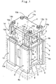
- numeral 1 designates a body frame of a linear motor press.
- Four thrust bearing 6 are provided at the inner bottom side of the body frame 1 and further four thrust bearing 7 are provided also at the upper side of the body frame 1, and four guide posts 3 are supported movable up and down at the thrust bearing 6,7.
- Each of the four guide posts 3 is fixed to a frame 5 movable up and down within the body frame 1.
- a bolster 2 is fixed on the upper side of the body frame 1, and a slide 4 is fixed horizontally to the top end of the four guide posts 3 projecting upward from the body frame 1 and the bolster 2.
- four linear motors 8 - 11 are arranged so that the vertical movable frame 5, the guide posts 3 and the slide 4 are driven and moved up and down.
- a lower mold (not shown) is fixed on the bolster 2, and an upper mold is fixed on the lower surface of the slide 4.
- Each of the four linear motors 8 - 11 is arranged in the longitudinal direction to the lateral side of the vertical movable frame 5 at the inside of the body frame 1, and coil slides (stators in this embodiment) 8a - 11a of the linear motors 8 - 11 are fixed to the side of the body frame 1, and magnet plates (travelers in this embodiment) 8b - 11b of the linear motors 8 - 11 are fixed to the side of the vertical movable frame 5. Further corresponding to the linear motors. 8 - 11, four linear scales (position detectors) 12 - 15 are arranged in the vicinity of the guide posts 3 at the lateral side of the slide 4.
- Stators 12a - 15a of the linear scales 12 - 15 are mounted on the upper side of the body frame 1 through a bracket, and travelers 12b - 15b of the linear scales 12 - 15 are mounted in the vicinity of the guide posts 3 at the lateral side of the slide 4.
- the linear scales 12 - 15 for example, that of absolute type is used, and the position data in the absolute type are outputted.
- the vertical movable frame 5 due to the reciprocation motion of the linear motors 8 - 11, the vertical movable frame 5, the guide posts 3 and the slide 4 as one body are moved up and down by controlled velocity and stroke, and based on the data of the moving position outputted from the linear scales 12 - 15, the moving of the slide 4 is controlled at high accuracy.
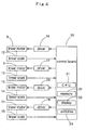
- Fig. 4 shows a control board (control circuit) 20 of a linear motor press and connection state of a linear motor or the like connected there.
- the control circuit 20 is constituted by a CPU 21 being the essential part, and controls operation of the press based on program data previously stored in a fixed memory.
- the control circuit 20 is provided with a temporary memory 22 which can be read and written at any time, a display 23, and switches 24 for inputting or operating various sorts of set values.
- a memory area is provided for storing press operation pattern program data previously registered, stroke length, SPM value (number of stroke per minute), die height set value, press set times or the like set and inputted. Set stroke length, SPM value, die height set value, press set times or the like are displayed on the display 23 for displaying the set screen.
- the linear scales 12 - 15 as above described are connected to an interface circuit within the control circuit 20, and sends reading of each of the linear scales 12 - 15, i.e., the position detection data (real position data) of the slide 4 to the control circuit 20.
- Drivers 16 - 19 are connected respectively to the four linear motors 8 - 11, and are connected also to the interface circuit within the control circuit 20.
- the linear motors 8 - 11 for example, that of AC servo motor (three--phase synchronous motor) system having large thrust is used, and the drivers 16 - 19 have a servo amplifier for example and drive the linear motors 8 - 11 in response to the command value outputted from the control circuit 20.
- control circuit 20 fetches the real position data from the linear scales 12 - 15 (step 101).
- step 102 From the optimum pattern of behavior of the slide 4 fixed and stored previously, a command value to be subsequently outputted is read out and error between the fixed command value of the optimum pattern and the real position data is calculated (step 102).
- step 103 decision is effected regarding whether or not a prescribed period of time lapses from the drive start of the slide 4 (step 103).
- the prescribed period of time is set to the time until the actual behavior of the slide 4 converged to the optimum pattern by the execution of the learning control.
- step 104 Immediately after the drive start of the slide 4, the decision result in the step 103 becomes "YES” and next decision is effected regarding whether or not it is without error (step 104).
- the error component is added to the fixed command value of the optimum pattern and the command value to be outputted is corrected (step 105), and the command value after the correction is outputted to the drivers 16 - 19 (step 106).
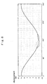
- the command value corresponding to the pattern after the correction shown by dash-and-dot line in Fig. 6 is outputted from the control circuit 20.
- the decision result in the step 103 is reversed to "YES", and decision is effected regarding whether or not the error exceeds the allowable value (step 108).
- the allowable value is set based on the machining error, for example, error produced due to generation of breakage of a metal mold, rise of shavings, life of the metal mold, twice punching or the like.
- the actual behavior pattern based on the real position data is compared with the behavior pattern in each error previously fixed and stored in each error, and sort of the error corresponding to the coincident behavior pattern is displayed on the display 23 (step 109), and the linear motors 8 - 11 are stopped in driving (step 110).
- control circuit 20 stores the result of the learning control, in other words, the command value after the correction or the error.
- the stored command value after the correction or the error can be utilized in the slide control of another linear motor press operating the slide by the same optimum pattern as the optimum pattern of the behavior of the slide of the linear motor press. In this case, as described later, this is particularly effective in the slide control of a linear motor press not having a linear scale (temporarily called a usual linear motor press).
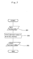
- Fig. 7 is a flow chart showing processing content of a slide control device of a usual linear motor press, that is, a slide control device of a usual linear motor press constituted by the linear motor press itself with a linear scale shown in Fig. 1 excluding the linear scale, or a slide control device of a linear motor press of the same sort as that of the linear motor press with a linear scale shown in Fig. 1 and not having a linear scale.
- the slide control device of the usual linear motor press controls the behavior of the slide so as to be coincident with the optimum pattern even if a linear scale is not installed, by utilizing the learning result obtained by the slide control device of the linear motor press with the linear scale as above described, that is, the command value after the correction or the error within the prescribed period of time.
- the slide control device of the usual linear motor press fetches the learning data being the result of the learning control using the slide control device of the linear motor press with the linear scale as above described from the memory of the slide control device of the linear motor press with the linear scale to the control device (step 201), and writes the command value or the error of the learning data into the memory (step 202). And then, when the slide is operated, the command value or the error is read out from the memory, and the read-out command value or the command value calculated from the read-out error is outputted (step 203).
- Fig. 8 is a schematic constitution diagram of a servo motor press in place of a conventional link press.
- a servo motor 51 is arranged so that the axial line of an output shaft 51a is slightly rockable on the vertical surface with respect to the point F as the rocking center to the body frame 1.
- a male screw part 53a of a ball screw 53 is connected to the output shaft 51a of the servo motor 51 through a coupling 52.
- One end of a first lever 54 is pin-coupled with the body frame 1, and other end thereof is pin-coupled with a female screw part 53b of the ball screw 53.
- One end of a second lever 55 is pin-coupled with a coupling member 56 fixed to each guide post 3, and other end of the second lever 55 is pin-coupled also with the female screw part 53b.
- the forward and reverse rotational motion of the servo motor 51 is converted into the linear reciprocation motion of the female screw part 53b through the coupling 52 and the male screw part 53a. Since the first lever 54 is connected to the female screw part 53b, and attendant on the motion of the female screw part 53b, the first lever 54 rocks with respect to the point A as the rocking center, the linear reciprocation motion of the female screw part 53b can be strictly said the rocking motion with respect to the point A as the rocking center. Due to the rocking motion of the female screw part 53b, the point C of the second lever 55 is moved in reciprocation up and down, and the slide 4 is moved up and down through the coupling member 56 and the guide post 3.
- a linear scale 57 having similar constitution to that of the linear scales 12 - 15 as above described is arranged between the body frame 1 and the slide 4.
- numeral 2 designates a bolster
- numeral 58 designates a thrust bearing.
- control circuit 1 ⁇ fixes and stores previously the optimum pattern command value of the behavior of the slide 4, and calculates error between the real position data from the position detector (linear scale 57) and the fixed command value of the optimum pattern in a prescribed period of time from the drive start of the slide, and corrects the command value to be outputted in order to eliminate the error, and outputs the command value after the correction and controls the servo motor 51, and 2 ⁇ stops the servo motor after lapse of the prescribed period of time if the error between the real position data and the fixed command value of the optimum pattern exceeds the allowable value based on the machining error, and 3 ⁇ stores the command value after the correction or the error within the prescribed period of time.
- a slide control device of a servo motor press not having a linear scale temporaryly called a usual servo motor press
- a usual servo motor press constituted by the servo motor press itself with the linear scale as shown in Fig. 8 excluding the linear scale
- a usual servo motor press constituted by a servo motor press of the same sort as that of the servo motor press with the linear scale as shown in Fig.
- servo motor press is not limited to that shown in Fig. 8 where a servo motor is used as a power source of a conventional link press, but can be applied also to a press of crank type or cam type.
- the learning control is adopted in the slide control of the linear motor press or the servo motor press, and the actual behavior pattern of the slide is converged to the optimum pattern thereby breakage of a metal mold or the like can be prevented. Further after the learning control, generation of the machining error is detected and the linear motor or the servo motor is stopped in driving thereby the improvement of the yield, prevention of breakage of a metal mold or the like can be intended.
- the result of the learning control is stored thereby the control result can be utilized in the slide control of another usual linear motor press or a usual servo motor press.
Landscapes
- Engineering & Computer Science (AREA)
- Mechanical Engineering (AREA)
- Physics & Mathematics (AREA)
- Electromagnetism (AREA)
- Control Of Presses (AREA)
Claims (5)
- Presse, die mit einer Stößelsteuerung versehen ist und aufweist:einen Motor (8-11) zum Antreiben eines Stößels (4) hin und her,einen Positionsdetektor (12-15) zum Detektieren der augenblicklichen Position des Stößels (4), undeine Steuerungsschaltung (20) miteinem Mittel zum Bestimmen und anschließenden Speichern eines Musters von Befehlswerten, die für einen gewünschten Stößelzyklus kennzeichnend sind,einem Mittel zum Berechnen eines Fehlerwerts, der zwischen dem augenblicklichen Befehlswert und dem tatsächlichen Positionswert, der von dem Positionsdetektor detektiert worden ist, vorhanden ist,einem Mittel zum Korrigieren des augenblicklichen Befehlswertes vor seiner Ausgabe, um den vorhandenen Fehler zu eliminieren, wobei das Korrigieren nur so lange durchgeführt wird, so lange die Pressebetriebszeit eine vorgeschriebene Grenze nicht erreicht hat,einem Mittel zum Speichern des berechneten Fehlers oder des korrigierten Befehlswertes, wodurch veranlasst wird, den entsprechenden Wert in dem Befehlsmuster ebenfalls zu korrigieren, wobei das Speichern und die Korrektur nur durchgeführt werden, so lange die Pressebetriebszeit eine vorgeschriebene Grenze nicht erreicht hat, undeinem Mittel zum Ausgeben des korrigierten Befehlswertes und zum Steuern des Motors.
- Presse nach Anspruch 1, wobei die Steuerschaltung (20) den Motor (8-11) nach Verstreichen der vorgeschriebenen Zeitperiode anhält, wenn der Fehler zwischen den realen Positionsdaten und dem festen Befehlswert des optimalen Musters den erlaubten Wert, der auf dem Bearbeitungsfehler basiert, überschreitet.
- Presse nach Anspruch 1 oder 2, wobei der Befehlswert nach der Korrektur gespeichert wird, um in einer Stößelsteuerung einer anderen Presse verwendet zu werden.
- Presse nach einem der Ansprüche 1 bis 3, wobei der Motor (8-11) ein Linearmotor ist.
- Presse nach einem der Ansprüche 1 bis 3, wobei der Motor (8-11) ein Servomotor ist.
Applications Claiming Priority (4)
| Application Number | Priority Date | Filing Date | Title |
|---|---|---|---|
| JP6581998 | 1998-03-16 | ||
| JP6581998 | 1998-03-16 | ||
| JP17599598 | 1998-06-23 | ||
| JP17599598 | 1998-06-23 |
Publications (3)
| Publication Number | Publication Date |
|---|---|
| EP0943422A2 EP0943422A2 (de) | 1999-09-22 |
| EP0943422A3 EP0943422A3 (de) | 1999-10-13 |
| EP0943422B1 true EP0943422B1 (de) | 2004-05-19 |
Family
ID=26406960
Family Applications (1)
| Application Number | Title | Priority Date | Filing Date |
|---|---|---|---|
| EP98119309A Expired - Lifetime EP0943422B1 (de) | 1998-03-16 | 1998-10-13 | Steuervorrichtung für den Stössel einer Presse |
Country Status (3)
| Country | Link |
|---|---|
| US (1) | US6070521A (de) |
| EP (1) | EP0943422B1 (de) |
| DE (1) | DE69823977T2 (de) |
Families Citing this family (17)
| Publication number | Priority date | Publication date | Assignee | Title |
|---|---|---|---|---|
| US6520077B1 (en) | 1999-03-31 | 2003-02-18 | Aida Engineering Co., Ltd. | Screw press |
| JP2001162400A (ja) * | 1999-12-10 | 2001-06-19 | Aida Eng Ltd | スクリュープレス |
| WO2002090096A1 (fr) * | 2001-04-26 | 2002-11-14 | Sodick Co., Ltd. | Presse et machine-outil |
| US6688216B2 (en) * | 2001-06-06 | 2004-02-10 | The Minster Machine Company | Method and apparatus for adjusting the gib-slide clearance using a pressurized chamber combination |
| DE50111859D1 (de) * | 2001-11-06 | 2007-02-22 | Haulick & Roos Gmbh | Press- oder Stanzautomat |
| EP1509346B1 (de) * | 2002-06-03 | 2006-09-20 | Novelis, Inc. | Linearantrieb einer umformmaschine |
| JP4408844B2 (ja) * | 2005-07-05 | 2010-02-03 | ファナック株式会社 | サーボダイクッションの制御装置 |
| DK2147265T3 (da) * | 2007-05-22 | 2012-07-02 | Als S R L | Køleindretning og fremgangsmåde til recirkulering af kølefluid forbundet dermed |
| EP2218171A4 (de) * | 2007-11-09 | 2012-03-21 | Vamco Int Inc | Antriebsvorrichtung und verfahren für eine pressmaschine |
| US20090126545A1 (en) * | 2007-11-15 | 2009-05-21 | Advanced Foundry Specialist, Llc | Automated trim press and shuttle system |
| AT509090B1 (de) | 2009-12-03 | 2014-03-15 | Andritz Tech & Asset Man Gmbh | Presse zum erzeugen einer druckkraft für die bearbeitung eines werkstücks |
| DE102009057409B4 (de) * | 2009-12-08 | 2013-02-28 | Schuler Pressen Gmbh & Co. Kg | Stößelantrieb mit Belastungsprofilanpasssung |
| US9931684B2 (en) | 2014-04-18 | 2018-04-03 | Honda Motor Co., Ltd. | Forming die and method of using the same |
| US10105742B2 (en) | 2014-12-09 | 2018-10-23 | Honda Motor Co., Ltd. | Draw press die assembly and method of using the same |
| US10068455B1 (en) * | 2017-04-13 | 2018-09-04 | Steven Label Corporation | Machine press data monitoring and analysis system |
| EP4073767A4 (de) | 2019-12-10 | 2024-01-31 | Barnes Group Inc. | Drahtloser sensor mit bakentechnik |
| CN111791526B (zh) * | 2020-07-14 | 2021-06-22 | 江苏轻石科技有限公司 | 一种高效率市政垃圾集中压缩一体化处理装置 |
Citations (2)
| Publication number | Priority date | Publication date | Assignee | Title |
|---|---|---|---|---|
| JPS60191700A (ja) * | 1984-03-10 | 1985-09-30 | Aida Eng Ltd | 液圧プレス |
| US5813322A (en) * | 1995-01-31 | 1998-09-29 | Komatsu Ltd. | Die height correcting apparatus for press |
Family Cites Families (24)
| Publication number | Priority date | Publication date | Assignee | Title |
|---|---|---|---|---|
| GB1195694A (en) * | 1966-08-24 | 1970-06-17 | Paul Granby & Company Ltd | Improvements in or relating to Forging Hammers, Presses and the like |
| FR2247344A1 (en) * | 1973-10-12 | 1975-05-09 | Chimkentsky | Mechanical press ram stroke regulator - has speed sensor with armature formed by secondary system of linear motor |
| SE426372B (sv) * | 1981-05-19 | 1983-01-17 | Alfa Laval Ab | Sett och anordning for overvakning av en press |
| JPS5821130A (ja) * | 1981-07-30 | 1983-02-07 | Komatsu Ltd | プレス機械の荷重測定装置 |
| JPS59110500A (ja) * | 1982-12-16 | 1984-06-26 | Yamada Dobby Co Ltd | プレス機の下死点位置補正装置 |
| JPS6021840B2 (ja) * | 1983-02-18 | 1985-05-29 | 株式会社 山田ドビ− | プレス機のスライドの下死点位置補正装置 |
| US4633720A (en) * | 1984-12-17 | 1987-01-06 | Dybel Frank Richard | Load monitoring system for progressive dies |
| JPS6264500A (ja) * | 1985-09-13 | 1987-03-23 | Yamada Dobby Co Ltd | プレス機のスライド下死点位置補正装置 |
| JPS63178000A (ja) * | 1987-01-20 | 1988-07-22 | Mitsubishi Heavy Ind Ltd | 可変速プレスの下死点制御装置 |
| JPH01299798A (ja) * | 1988-05-27 | 1989-12-04 | Yamada Dobby Co Ltd | プレス機における下死点位置補正装置 |
| AU621146B2 (en) * | 1988-09-08 | 1992-03-05 | Trw Steering & Industrial Products (Japan) Co., Ltd. | Apparatus and method of detecting abnormal load of pressurizing apparatus |
| JPH0831635B2 (ja) * | 1989-05-12 | 1996-03-27 | 富士電機株式会社 | ピエゾアクチュエータの駆動電源装置 |
| EP0432094B1 (de) * | 1989-11-22 | 1993-12-08 | Cybelec S.A. | Verfahren zur Steuerung der Bahn eines Stanzwerkzeugs |
| US5197186A (en) * | 1990-05-29 | 1993-03-30 | Amp Incorporated | Method of determining the quality of a crimped electrical connection |
| JP3169247B2 (ja) * | 1991-12-03 | 2001-05-21 | 株式会社石井工作研究所 | プレス機械の加圧力自動制御方法とその装置 |
| JPH05169151A (ja) * | 1991-12-16 | 1993-07-09 | Mekatoro Joban Internatl:Kk | パンチプレス機 |
| US5483874A (en) * | 1994-03-18 | 1996-01-16 | Janome Sewing Machine Co., Ltd. | Electropressing apparatus with computer programmable control |
| US5502996A (en) * | 1994-12-12 | 1996-04-02 | The Whitaker Corporation | Crimping press actuator assembly |
| JP3606390B2 (ja) * | 1994-12-21 | 2005-01-05 | 株式会社小松製作所 | 油圧プレスの金型保護装置 |
| US5669257A (en) * | 1994-12-28 | 1997-09-23 | Yazaki Corporation | Method of crimping terminal and apparatus for the same |
| JP4093379B2 (ja) * | 1996-05-21 | 2008-06-04 | 蛇の目ミシン工業株式会社 | 電動プレス |
| JPH1050449A (ja) * | 1996-07-31 | 1998-02-20 | Yazaki Corp | 端子圧着装置 |
| US5813274A (en) * | 1996-09-20 | 1998-09-29 | The Whitaker Corporation | Magnetic press |
| JPH10202397A (ja) * | 1996-11-19 | 1998-08-04 | Yamada Dobby Co Ltd | プレス機 |
-
1998
- 1998-10-13 EP EP98119309A patent/EP0943422B1/de not_active Expired - Lifetime
- 1998-10-13 DE DE1998623977 patent/DE69823977T2/de not_active Expired - Lifetime
- 1998-10-16 US US09/173,564 patent/US6070521A/en not_active Expired - Lifetime
Patent Citations (2)
| Publication number | Priority date | Publication date | Assignee | Title |
|---|---|---|---|---|
| JPS60191700A (ja) * | 1984-03-10 | 1985-09-30 | Aida Eng Ltd | 液圧プレス |
| US5813322A (en) * | 1995-01-31 | 1998-09-29 | Komatsu Ltd. | Die height correcting apparatus for press |
Also Published As
| Publication number | Publication date |
|---|---|
| EP0943422A2 (de) | 1999-09-22 |
| EP0943422A3 (de) | 1999-10-13 |
| DE69823977T2 (de) | 2005-05-19 |
| DE69823977D1 (de) | 2004-06-24 |
| US6070521A (en) | 2000-06-06 |
Similar Documents
| Publication | Publication Date | Title |
|---|---|---|
| EP0943422B1 (de) | Steuervorrichtung für den Stössel einer Presse | |
| US6619088B1 (en) | Bottom dead center correction device for servo press machine | |
| US20230040955A1 (en) | Transfer apparatus and transfer method | |
| US6206266B1 (en) | Control method for wire bonding apparatus | |
| CN101470243B (zh) | 摄像设备及其控制方法 | |
| JP2000006211A (ja) | 電動式型締装置 | |
| JP3818788B2 (ja) | プレス機のスライド制御装置 | |
| US6119917A (en) | Wire bonding apparatus and bonding load correction method for the same | |
| EP0960665A1 (de) | System zur Steuerung einer Zuführvorrichtung für Bahnmaterial | |
| JP3850131B2 (ja) | リニアモータプレス機の下死点制御装置 | |
| JP2000280100A (ja) | サーボプレス機械の下死点補正装置 | |
| JPH0773800B2 (ja) | プレス装置 | |
| JPH10193200A (ja) | 油圧プレスの油圧回路故障診断装置及びその方法 | |
| JPH06307898A (ja) | 検出器の異常監視装置 | |
| JP3418264B2 (ja) | リードフレームのディプレス加工装置およびその制御方法 | |
| JPH09111576A (ja) | 織機の開口装置に用いる回転原点位置決定装置 | |
| JPH11254191A (ja) | プレス機 | |
| JP2000176699A (ja) | プレス機械の下死点位置制御装置 | |
| JPH11226796A (ja) | 高精度c型フレームプレス | |
| JP2008543250A (ja) | リニア駆動装置の位置制御方法及び/又は速度制御方法 | |
| JPH0470414B2 (de) | ||
| CN113125506B (zh) | 光栅尺、磁栅尺的诊断方法、系统及存储介质 | |
| JP2001300799A (ja) | サーボプレス | |
| JPH11254192A (ja) | リニアモータプレス機の制御装置 | |
| EP0909015A3 (de) | Verfahren zur Steuerung eines Servomotors |
Legal Events
| Date | Code | Title | Description |
|---|---|---|---|
| PUAI | Public reference made under article 153(3) epc to a published international application that has entered the european phase |
Free format text: ORIGINAL CODE: 0009012 |
|
| PUAL | Search report despatched |
Free format text: ORIGINAL CODE: 0009013 |
|
| AK | Designated contracting states |
Kind code of ref document: A2 Designated state(s): CH DE FR GB LI |
|
| AX | Request for extension of the european patent |
Free format text: AL;LT;LV;MK;RO;SI |
|
| AK | Designated contracting states |
Kind code of ref document: A3 Designated state(s): AT BE CH CY DE DK ES FI FR GB GR IE IT LI LU MC NL PT SE |
|
| AX | Request for extension of the european patent |
Free format text: AL;LT;LV;MK;RO;SI |
|
| 17P | Request for examination filed |
Effective date: 20000114 |
|
| AKX | Designation fees paid |
Free format text: CH DE FR GB LI |
|
| 17Q | First examination report despatched |
Effective date: 20011026 |
|
| GRAP | Despatch of communication of intention to grant a patent |
Free format text: ORIGINAL CODE: EPIDOSNIGR1 |
|
| GRAS | Grant fee paid |
Free format text: ORIGINAL CODE: EPIDOSNIGR3 |
|
| GRAA | (expected) grant |
Free format text: ORIGINAL CODE: 0009210 |
|
| AK | Designated contracting states |
Kind code of ref document: B1 Designated state(s): CH DE FR GB LI |
|
| REG | Reference to a national code |
Ref country code: GB Ref legal event code: FG4D |
|
| REG | Reference to a national code |
Ref country code: CH Ref legal event code: EP |
|
| REF | Corresponds to: |
Ref document number: 69823977 Country of ref document: DE Date of ref document: 20040624 Kind code of ref document: P |
|
| REG | Reference to a national code |
Ref country code: CH Ref legal event code: NV Representative=s name: E. BLUM & CO. PATENTANWAELTE |
|
| ET | Fr: translation filed | ||
| PLBE | No opposition filed within time limit |
Free format text: ORIGINAL CODE: 0009261 |
|
| STAA | Information on the status of an ep patent application or granted ep patent |
Free format text: STATUS: NO OPPOSITION FILED WITHIN TIME LIMIT |
|
| 26N | No opposition filed |
Effective date: 20050222 |
|
| REG | Reference to a national code |
Ref country code: CH Ref legal event code: PFA Owner name: YAMADA DOBBY CO., LTD. Free format text: YAMADA DOBBY CO., LTD.#35, AZA-SHIMOSHINDEN#TAMANO, BISAI-SHI AICHI-KEN, 494 (JP) -TRANSFER TO- YAMADA DOBBY CO., LTD.#35, AZA-SHIMOSHINDEN#TAMANO, BISAI-SHI AICHI-KEN, 494 (JP) |
|
| REG | Reference to a national code |
Ref country code: FR Ref legal event code: PLFP Year of fee payment: 18 |
|
| REG | Reference to a national code |
Ref country code: FR Ref legal event code: PLFP Year of fee payment: 19 |
|
| REG | Reference to a national code |
Ref country code: FR Ref legal event code: PLFP Year of fee payment: 20 |
|
| PGFP | Annual fee paid to national office [announced via postgrant information from national office to epo] |
Ref country code: FR Payment date: 20171023 Year of fee payment: 20 Ref country code: DE Payment date: 20171009 Year of fee payment: 20 |
|
| PGFP | Annual fee paid to national office [announced via postgrant information from national office to epo] |
Ref country code: CH Payment date: 20171023 Year of fee payment: 20 Ref country code: GB Payment date: 20171024 Year of fee payment: 20 |
|
| REG | Reference to a national code |
Ref country code: DE Ref legal event code: R071 Ref document number: 69823977 Country of ref document: DE |
|
| REG | Reference to a national code |
Ref country code: CH Ref legal event code: PL |
|
| REG | Reference to a national code |
Ref country code: GB Ref legal event code: PE20 Expiry date: 20181012 |
|
| PG25 | Lapsed in a contracting state [announced via postgrant information from national office to epo] |
Ref country code: GB Free format text: LAPSE BECAUSE OF EXPIRATION OF PROTECTION Effective date: 20181012 |