EP0460633B1 - Verfahren zur Herstellung von Reissverschlüssen - Google Patents
Verfahren zur Herstellung von Reissverschlüssen Download PDFInfo
- Publication number
- EP0460633B1 EP0460633B1 EP91109185A EP91109185A EP0460633B1 EP 0460633 B1 EP0460633 B1 EP 0460633B1 EP 91109185 A EP91109185 A EP 91109185A EP 91109185 A EP91109185 A EP 91109185A EP 0460633 B1 EP0460633 B1 EP 0460633B1
- Authority
- EP
- European Patent Office
- Prior art keywords
- units
- stringer chain
- unit
- end stop
- chain
- Prior art date
- Legal status (The legal status is an assumption and is not a legal conclusion. Google has not performed a legal analysis and makes no representation as to the accuracy of the status listed.)
- Expired - Lifetime
Links
Images


Classifications
-
- A—HUMAN NECESSITIES
- A44—HABERDASHERY; JEWELLERY
- A44B—BUTTONS, PINS, BUCKLES, SLIDE FASTENERS, OR THE LIKE
- A44B19/00—Slide fasteners
- A44B19/42—Making by processes not fully provided for in one other class, e.g. B21D53/50, B21F45/18, B22D17/16, B29D5/00
-
- Y—GENERAL TAGGING OF NEW TECHNOLOGICAL DEVELOPMENTS; GENERAL TAGGING OF CROSS-SECTIONAL TECHNOLOGIES SPANNING OVER SEVERAL SECTIONS OF THE IPC; TECHNICAL SUBJECTS COVERED BY FORMER USPC CROSS-REFERENCE ART COLLECTIONS [XRACs] AND DIGESTS
- Y10—TECHNICAL SUBJECTS COVERED BY FORMER USPC
- Y10T—TECHNICAL SUBJECTS COVERED BY FORMER US CLASSIFICATION
- Y10T29/00—Metal working
- Y10T29/49—Method of mechanical manufacture
- Y10T29/49782—Method of mechanical manufacture of a slide fastener
-
- Y—GENERAL TAGGING OF NEW TECHNOLOGICAL DEVELOPMENTS; GENERAL TAGGING OF CROSS-SECTIONAL TECHNOLOGIES SPANNING OVER SEVERAL SECTIONS OF THE IPC; TECHNICAL SUBJECTS COVERED BY FORMER USPC CROSS-REFERENCE ART COLLECTIONS [XRACs] AND DIGESTS
- Y10—TECHNICAL SUBJECTS COVERED BY FORMER USPC
- Y10T—TECHNICAL SUBJECTS COVERED BY FORMER US CLASSIFICATION
- Y10T29/00—Metal working
- Y10T29/51—Plural diverse manufacturing apparatus including means for metal shaping or assembling
- Y10T29/5101—Slide fastener or slide fastener element
-
- Y—GENERAL TAGGING OF NEW TECHNOLOGICAL DEVELOPMENTS; GENERAL TAGGING OF CROSS-SECTIONAL TECHNOLOGIES SPANNING OVER SEVERAL SECTIONS OF THE IPC; TECHNICAL SUBJECTS COVERED BY FORMER USPC CROSS-REFERENCE ART COLLECTIONS [XRACs] AND DIGESTS
- Y10—TECHNICAL SUBJECTS COVERED BY FORMER USPC
- Y10T—TECHNICAL SUBJECTS COVERED BY FORMER US CLASSIFICATION
- Y10T29/00—Metal working
- Y10T29/53—Means to assemble or disassemble
- Y10T29/53291—Slide fastener
Definitions
- This invention relates to a process of manufacturing slide fasteners from an elongate stringer chain (100) which comprises feeding said stringer chain (100) sequentially along a path of processing through a plurality of processing units including a gapping unit (11), a bottom end stop appyling unit (12), a slider applying unit, a top end stop applying unit and a stringer chain cutting unit.
- GB-A- 221 953 which forms the basis of claim 1 discloses a process for controlling the entire apparatus for making slide fastener products of different lengths, styles, sizes and/or colors.
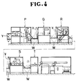
- the arrangement of such prior art apparatus is shown in figure 4 of the accompanying drawings in which a buffer W or storage device is provided between succeeding machines including a gapping machine P, a bottom stop fitting machine Q, a slider mounting machine R, a top stop fitting machine S and a cutting machine T, the maximum and minimum level of workpiece supply Y in the buffer W being a determining factor to continue or discontinue the operation of the respective upstream and downstream machines.
- the present invention seeks to provide a process of the type mentioned above which will eliminate the foregoing drawbacks of the prior art and which will enable an automatic mass production of slide fasteners with utmost efficiency and accuracy.
- a process satisfying these requirements is characterized by holding said stringer chain (100) in substantially tensionless condition by allowing it to sag by its own gravity at least over a predetermined slide fastener product length between each adjacent pair of said units (11; 12; 13); and effecting the operation of each of said units in synchronism with a selected one of said units which has the slowest cycle of operation.
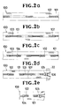
- stringer chain 100 designates an elongate strip ( Figure 2a) comprising a pair of oppositely disposed tapes 101 and a row of coupling elements 102 secured to and along an inner longitudinal edge of each of the tapes 101.
- FIG. 1 shows a general layout of an apparatus employed to carry the process of the invention into practice.
- the apparatus 10 essentially comprises a gapping unit 11 for removing a predetermined number of coupling elements 102 to provide a gap or an element-devoid space portion 103 (Figure 2b); a bottom end stop applying unit 12 for applying a bottom end stop 104 at the trailing end of each gap 103 ( Figure 2c); and a combination unit 13 including a slider applying unit for mounting a slider 105 ( Figure 2d) astride the coupling elements 102 on the pair of opposed tapes 101, a top end stop applying unit for applying a top end stop 106 (Figure 2d) at the end of a terminal element 102 on each tape 101, and a cutting unit for cutting the tapes 101 transversely across the center line 107 ( Figure 2d) of each gap 103.
- a gapping unit 11 for removing a predetermined number of coupling elements 102 to provide a gap or an element-devoid space portion 103 ( Figure 2b);
- the stringer chain 100 is metered, cut to a predetermined length and stored in a stockyard 14 in advance of entry into the processing apparatus 10.
- the stringer chain 100 passes through a first detector 15 operatively associated with a metering roll 16 and stops upon movement for a distance corresponding to one slide fastener product length, during which time the stringer chain 100 is gapped by the gapping unit 11. This is followed by operation of a first feed roller 17 to advance the stringer chain 100.
- the first feed roller 17 is controlled so as to begin its rotation in synchronism with an operating cycle of a slowest processing unit in the apparatus 10 which is the combination slider and top end stop applying and cutting unit 13 as exemplified in the illustrated embodiment.
- a completion of one operating cycle of the slowest unit 13 dictates the first feed roller 17 to advance or feed the downstream portion of the stringer chain 100 through a first guide roll 18 onto the bottom end stop applying unit 12 and the upstream portion of the chain 100 onto the gapping unit 11.
- a second feed roller 19 operates in synchronism with the operating cycle of the slowest unit 13 and draws the stringer chain 100 forwardly onto the bottom end stop applying unit 12.
- a second detector 20 monitors the movement of the stringer chain 100 for a distance corresponding to one slide fastener product length and dictates the second feed roller 19 to stop so as to allow the unit 12 to apply a bottom end stop 104 to the upstream terminal elements 102 of the stringer chain 100 as depicted in Figure 2c.
- the stringer chain 100 is always held in tensionless condition by allowing it to sag by its own gravity at least over one slide fastener product length between the first feed roller 17 adjacent to the gapping unit 11 and the first guide roll 18 immediately upstream of the bottom end stop applying unit 12 and also between the second feed roller 19 immediately downstream of the bottom end stop applying unit 12 and a second guide roll 21 immediately upstream of the combination unit 13, as illustrated in Figure 1.
- the distance over which the stringer chain 100 is held substantially tensionless may be greater than one slide fastener product length where the product is relatively short.
- the stringer chain 100 now assembled with a bottom end stop 104 is further advanced by means of feed grippers 22, 22 onto the combination unit 13, wherein the chain 100 is assembled with a slider 105 and top end stops 106 supplied from a parts holder 23.
- the stringer chain 100 thus assembled with slider 105 and top end stops 106 as depicted in Figure 2d is gripped and pulled toward an outlet end of the apparatus 10 by a take-out gripper 24 for a distance corresponding to one slide fastener length as detected by a third detector 25, whereupon the stringer chain 100 is cut by a cutter 26 transversely across the cutting line 107 centrally of the gap 103 to produce a finished slide fastener 108 ( Figure 2e) which is further carried onward by the gripper 24 over to a conveyor 27, thence to a product tray 28 in which finished slide fasteners are stacked and bundled in a manner well known in the art.
- the gaps 103 are utilized for actuating the second detector 20 and the third detectors 25 as for example by a mechanical means such as a pin installed at the gap 103, or by an optical means emitting a light beam through the gap 103 in a manner well known in the art, whereby the detectors 20 and 25 respectively read and signal one predetermined slide fastener product length after another over the stringer chain 100.
- the processing units 11, 12 and 13 are controlled for their respective cycles of operation by respective control devices (A), (B) and (C) as schematically illustrated in Figures 3a - 3c.
- Figure 3a shows a mode of control in which the control device (C) associated with the slowest processing unit (III) is arranged to supervise the other two control devices (B) and (C) linked to the processing units (I) and (II), respectively.
- the cycle of processing operation begins with the transmission of an information signal from each of the control devices (A) and (B) to the master control device (C) that the stringer chain 100 is ready to make advancing or feeding movement.
- the master control device (C) transmits an information signal to the control devices (A) and (B), respectively, to initiate feeding of the stringer chain 100, whereupon the units (I) and (II) are put into operation simultaneously and the stringer chain 100 is fed and monitored by the detectors 20 and 25, followed by assembling the chain 100 with the respective slide fastener component parts (bottom end stop 104, slider 105 and top end stops 106) at the respective units (I) and (II).
- An information signal representing the completion of the work of the respective units (I), (II) and (III) is transmitted from the respective control devices (A), (B) and (C) to the master control (C), whereupon the next cycle of operation begins with the transmission of a "feed-start" signal from the master control (C) to the respective control devices (A) and (B).
- the processing units (I) and (II) are thus operated in synchronized relation to the slowest working unit (III).
- FIG 3b shows another mode of control in which the processing unit (II) is the slowest and hence its associated control device (B) serves as a master to supervise the other two control devices (A) and (C).
- Figure 3c illustrates a further mode of control in which a central control device (D) is installed to supervise all of the three control devices (A), (B) and (C) so that the respective processing units (I), (II) and (III) are maintained in synchronized cycle of operation.
- D central control device
- the combination processing unit 13 may be built into separate units for applying sliders 105 and top end stops 106 respectively and cutting the stringer chain 100, thus providing a total of five stages of operation. It is also possible to connect the master control device (C), as shown in Figure 3a, to a computer control system (E) storing a specific production program designed to manufacture a variety of slide fastener products differing in style, length, color, etc., including for example a separable type of bottom end stop. Alternatively, such computer control system (E) may be connected to the central control device (D) for similar purposes.
Landscapes
- Slide Fasteners (AREA)
- Making Paper Articles (AREA)
Claims (2)
- Verfahren zur Herstellung von Reißverschlüssen aus einer langgestreckten Reißverschlußkette (100), bei dem die Reißverschlußkette (100) längs einer Bearbeitungsbahn nacheinander durch mehrere Bearbeitungseinheiten hindurchbewegt wird, umfassend eine Lückenbildungseinheit (11), eine untere Begrenzungsteil-Anbringeinheit (12), eine Schieber-Anbringeinheit, eine obere Begrenzungsteil-Anbringeinheit und eine Reißverschlußketten-Schneideinheit (13), dadurch gekennzeichnet, daß die Reißverschlußkette (100) in im wesentlichen spannungslosem Zustand gehalten wird, indem sie zumindest über eine bestimmte Länge eines Reißverschlußerzeugnisses zwischen jedem benachbarten Paar der besagten Einheiten (11; 12; 13) unter ihrem Eigengewicht durchhängen kann, und daß die Betätigung jeder der besagten Einheiten in zeitlicher Abhängigkeit von einer dieser Einheiten, die den langsamsten Arbeitszyklus hat, erfolgt.
- Verfahren nach Anspruch 1, ferner umfassend die Steuerung der Betätigung jeder der besagten Einheiten (11, 12, 13) mit einem Computerprogramm, das so ausgebildet ist, um hinsichtlich der Machart, Länge und/oder Farbe unterschiedliche Reißverschlüsse herzustellen.
Applications Claiming Priority (2)
| Application Number | Priority Date | Filing Date | Title |
|---|---|---|---|
| JP2147635A JPH0440902A (ja) | 1990-06-06 | 1990-06-06 | スライドフアスナーの製造方法 |
| JP147635/90 | 1990-06-06 |
Publications (3)
| Publication Number | Publication Date |
|---|---|
| EP0460633A2 EP0460633A2 (de) | 1991-12-11 |
| EP0460633A3 EP0460633A3 (en) | 1992-02-26 |
| EP0460633B1 true EP0460633B1 (de) | 1995-03-15 |
Family
ID=15434795
Family Applications (1)
| Application Number | Title | Priority Date | Filing Date |
|---|---|---|---|
| EP91109185A Expired - Lifetime EP0460633B1 (de) | 1990-06-06 | 1991-06-05 | Verfahren zur Herstellung von Reissverschlüssen |
Country Status (13)
| Country | Link |
|---|---|
| US (1) | US5181305A (de) |
| EP (1) | EP0460633B1 (de) |
| JP (1) | JPH0440902A (de) |
| KR (1) | KR930002700B1 (de) |
| AU (1) | AU627978B2 (de) |
| BR (1) | BR9102528A (de) |
| CA (1) | CA2043832C (de) |
| DE (1) | DE69108106T2 (de) |
| ES (1) | ES2069773T3 (de) |
| FI (1) | FI97772C (de) |
| HK (1) | HK105297A (de) |
| MY (1) | MY105507A (de) |
| ZA (1) | ZA914332B (de) |
Families Citing this family (3)
| Publication number | Priority date | Publication date | Assignee | Title |
|---|---|---|---|---|
| EP0771538B1 (de) * | 1995-05-09 | 2003-12-10 | Ykk Corporation | Verfahren zur herstellung von reissverschluss |
| US20030200650A1 (en) * | 2002-04-25 | 2003-10-30 | Ykk Corporation Of America | Slider mounting apparatus and method |
| WO2015072027A1 (ja) * | 2013-11-18 | 2015-05-21 | Ykk株式会社 | スライドファスナー排出装置 |
Citations (1)
| Publication number | Priority date | Publication date | Assignee | Title |
|---|---|---|---|---|
| GB2221953A (en) * | 1988-07-28 | 1990-02-21 | Opti Patent Forschung Fab | Controlling production plant for slide fasteners |
Family Cites Families (8)
| Publication number | Priority date | Publication date | Assignee | Title |
|---|---|---|---|---|
| US2885774A (en) * | 1957-05-13 | 1959-05-12 | Waldes Kohinoor Inc | Methods of producing combined slide fastener and hook-and-eye closure units |
| US3130476A (en) * | 1958-06-18 | 1964-04-28 | Gen Zipper Corp | Scoop cutting and bottom stop machines combination the machines and control means therefor |
| DE1610456A1 (de) * | 1964-03-31 | 1970-11-12 | Zentrale Entwicklung Konstrukt | Verfahren und Vorrichtung zum Konfektionieren der Reissverschluesse |
| US3530563A (en) * | 1966-06-27 | 1970-09-29 | Yoshida Kogyo Kk | Apparatus for automatically assembling slide fasteners |
| DE1806238C3 (de) * | 1968-10-31 | 1978-03-09 | William Prym-Werke Kg, 5190 Stolberg | Vorrichtung zum Einnähen eines fortlaufenden Reißverschlußbandes in einen durch einen Schlitz zweigeteilten Träger |
| JPS5852642B2 (ja) * | 1977-06-30 | 1983-11-24 | ワイケイケイ株式会社 | スライドファスナ−の製造方法 |
| DE3712401A1 (de) * | 1987-04-11 | 1988-10-27 | Opti Patent Forschung Fab | Verfahren zum betrieb einer fertigungsstrasse bei der herstellung von einzelnen reissverschluessen |
| AU620732B2 (en) * | 1989-09-12 | 1992-02-20 | Ykk Corporation | Method of and apparatus for manufacturing slide fasteners |
-
1990
- 1990-06-06 JP JP2147635A patent/JPH0440902A/ja active Pending
-
1991
- 1991-05-30 AU AU78061/91A patent/AU627978B2/en not_active Ceased
- 1991-06-04 CA CA002043832A patent/CA2043832C/en not_active Expired - Lifetime
- 1991-06-04 MY MYPI91000990A patent/MY105507A/en unknown
- 1991-06-05 ES ES91109185T patent/ES2069773T3/es not_active Expired - Lifetime
- 1991-06-05 EP EP91109185A patent/EP0460633B1/de not_active Expired - Lifetime
- 1991-06-05 US US07/710,546 patent/US5181305A/en not_active Expired - Fee Related
- 1991-06-05 FI FI912705A patent/FI97772C/fi not_active IP Right Cessation
- 1991-06-05 KR KR1019910009312A patent/KR930002700B1/ko not_active Expired - Fee Related
- 1991-06-05 DE DE69108106T patent/DE69108106T2/de not_active Expired - Lifetime
- 1991-06-06 BR BR919102528A patent/BR9102528A/pt not_active Application Discontinuation
- 1991-06-06 ZA ZA914332A patent/ZA914332B/xx unknown
-
1997
- 1997-06-26 HK HK105297A patent/HK105297A/en not_active IP Right Cessation
Patent Citations (1)
| Publication number | Priority date | Publication date | Assignee | Title |
|---|---|---|---|---|
| GB2221953A (en) * | 1988-07-28 | 1990-02-21 | Opti Patent Forschung Fab | Controlling production plant for slide fasteners |
Also Published As
| Publication number | Publication date |
|---|---|
| EP0460633A3 (en) | 1992-02-26 |
| BR9102528A (pt) | 1992-01-21 |
| ZA914332B (en) | 1992-03-25 |
| JPH0440902A (ja) | 1992-02-12 |
| HK105297A (en) | 1997-08-15 |
| DE69108106D1 (de) | 1995-04-20 |
| CA2043832A1 (en) | 1991-12-07 |
| ES2069773T3 (es) | 1995-05-16 |
| FI97772C (fi) | 1997-02-25 |
| KR930002700B1 (ko) | 1993-04-09 |
| AU627978B2 (en) | 1992-09-03 |
| FI912705A0 (fi) | 1991-06-05 |
| AU7806191A (en) | 1991-12-12 |
| FI97772B (fi) | 1996-11-15 |
| CA2043832C (en) | 1994-01-18 |
| FI912705L (fi) | 1991-12-07 |
| KR920000269A (ko) | 1992-01-29 |
| US5181305A (en) | 1993-01-26 |
| DE69108106T2 (de) | 1995-11-09 |
| EP0460633A2 (de) | 1991-12-11 |
| MY105507A (en) | 1994-10-31 |
Similar Documents
| Publication | Publication Date | Title |
|---|---|---|
| US4932113A (en) | Manufacture of slide fasteners | |
| US2708968A (en) | Method of producing measured lengths of slide fastener chain | |
| KR900004454B1 (ko) | 연결부분을 가진 기다란 제품의 절단 방법 및 장치 | |
| US4625375A (en) | Apparatus for automatically processing a slide fastener chain | |
| US5181305A (en) | Process for the manufacture of slide fasteners | |
| EP0269912B1 (de) | Vorrichtung zum Herstellen von Reissverschlüssen mit zwei Schiebern | |
| CA1312004C (en) | Elongate article processing apparatus with an improved discharge device | |
| KR870000858B1 (ko) | 분리 가능한 슬라이드 파스너의 제조방법 | |
| EP0458220B1 (de) | Verfahren zur Herstellung von Reissverschlüssen | |
| EP0771538B1 (de) | Verfahren zur herstellung von reissverschluss | |
| EP0069277B1 (de) | Verfahren und Vorrichtung zum Abtasten der Ende eines mit einer Reissverschlusskette verbundenen Klappenstückes | |
| EP0138230B1 (de) | Verfahren zur Befestigung von Schlitzleisten für Hosen an einer Reissverschlusskette | |
| JPH0397407A (ja) | スライドフアスナー製造方法 | |
| US5072502A (en) | Method and apparatus for applying slide fastener end stop | |
| CA1251022A (en) | Method of and apparatus for forming element-free spaces in continuous slide fastener chain with fly strips | |
| US4856695A (en) | Method of and apparatus for feeding slide fastener chain with fly strips | |
| EP0171781B1 (de) | Verfahren zum Abschneiden eines Reissverschlussbandes | |
| EP0292110A2 (de) | Verfahren und Vorrichtung zur Fütterung von Reissverschlussketten mit Hosenleisten | |
| HK21189A (en) | Apparatus for manufacturing slide fasteners with flies | |
| HK1017570B (en) | Method of manufacturing slide fastener |
Legal Events
| Date | Code | Title | Description |
|---|---|---|---|
| PUAI | Public reference made under article 153(3) epc to a published international application that has entered the european phase |
Free format text: ORIGINAL CODE: 0009012 |
|
| AK | Designated contracting states |
Kind code of ref document: A2 Designated state(s): BE CH DE ES FR GB IT LI NL SE |
|
| PUAL | Search report despatched |
Free format text: ORIGINAL CODE: 0009013 |
|
| AK | Designated contracting states |
Kind code of ref document: A3 Designated state(s): BE CH DE ES FR GB IT LI NL SE |
|
| 17P | Request for examination filed |
Effective date: 19920525 |
|
| 17Q | First examination report despatched |
Effective date: 19930716 |
|
| RAP1 | Party data changed (applicant data changed or rights of an application transferred) |
Owner name: YKK CORPORATION |
|
| GRAA | (expected) grant |
Free format text: ORIGINAL CODE: 0009210 |
|
| AK | Designated contracting states |
Kind code of ref document: B1 Designated state(s): BE CH DE ES FR GB IT LI NL SE |
|
| ET | Fr: translation filed | ||
| ITF | It: translation for a ep patent filed | ||
| REF | Corresponds to: |
Ref document number: 69108106 Country of ref document: DE Date of ref document: 19950420 |
|
| REG | Reference to a national code |
Ref country code: ES Ref legal event code: FG2A Ref document number: 2069773 Country of ref document: ES Kind code of ref document: T3 |
|
| PLBE | No opposition filed within time limit |
Free format text: ORIGINAL CODE: 0009261 |
|
| STAA | Information on the status of an ep patent application or granted ep patent |
Free format text: STATUS: NO OPPOSITION FILED WITHIN TIME LIMIT |
|
| 26N | No opposition filed | ||
| PGFP | Annual fee paid to national office [announced via postgrant information from national office to epo] |
Ref country code: SE Payment date: 19970312 Year of fee payment: 7 |
|
| PGFP | Annual fee paid to national office [announced via postgrant information from national office to epo] |
Ref country code: BE Payment date: 19970410 Year of fee payment: 7 |
|
| PGFP | Annual fee paid to national office [announced via postgrant information from national office to epo] |
Ref country code: ES Payment date: 19970602 Year of fee payment: 7 |
|
| PGFP | Annual fee paid to national office [announced via postgrant information from national office to epo] |
Ref country code: CH Payment date: 19970610 Year of fee payment: 7 |
|
| PGFP | Annual fee paid to national office [announced via postgrant information from national office to epo] |
Ref country code: NL Payment date: 19970630 Year of fee payment: 7 |
|
| PG25 | Lapsed in a contracting state [announced via postgrant information from national office to epo] |
Ref country code: SE Free format text: LAPSE BECAUSE OF NON-PAYMENT OF DUE FEES Effective date: 19980606 Ref country code: ES Free format text: LAPSE BECAUSE OF EXPIRATION OF PROTECTION Effective date: 19980606 |
|
| PG25 | Lapsed in a contracting state [announced via postgrant information from national office to epo] |
Ref country code: CH Free format text: LAPSE BECAUSE OF NON-PAYMENT OF DUE FEES Effective date: 19980630 Ref country code: LI Free format text: LAPSE BECAUSE OF NON-PAYMENT OF DUE FEES Effective date: 19980630 Ref country code: BE Free format text: LAPSE BECAUSE OF NON-PAYMENT OF DUE FEES Effective date: 19980630 |
|
| BERE | Be: lapsed |
Owner name: YKK CORP. Effective date: 19980630 |
|
| PG25 | Lapsed in a contracting state [announced via postgrant information from national office to epo] |
Ref country code: NL Free format text: LAPSE BECAUSE OF NON-PAYMENT OF DUE FEES Effective date: 19990101 |
|
| REG | Reference to a national code |
Ref country code: CH Ref legal event code: PL |
|
| EUG | Se: european patent has lapsed |
Ref document number: 91109185.8 |
|
| NLV4 | Nl: lapsed or anulled due to non-payment of the annual fee |
Effective date: 19990101 |
|
| REG | Reference to a national code |
Ref country code: ES Ref legal event code: FD2A Effective date: 20000201 |
|
| REG | Reference to a national code |
Ref country code: GB Ref legal event code: IF02 |
|
| PGFP | Annual fee paid to national office [announced via postgrant information from national office to epo] |
Ref country code: FR Payment date: 20100709 Year of fee payment: 20 |
|
| PGFP | Annual fee paid to national office [announced via postgrant information from national office to epo] |
Ref country code: IT Payment date: 20100619 Year of fee payment: 20 |
|
| PGFP | Annual fee paid to national office [announced via postgrant information from national office to epo] |
Ref country code: GB Payment date: 20100602 Year of fee payment: 20 Ref country code: DE Payment date: 20100602 Year of fee payment: 20 |
|
| REG | Reference to a national code |
Ref country code: DE Ref legal event code: R071 Ref document number: 69108106 Country of ref document: DE |
|
| REG | Reference to a national code |
Ref country code: DE Ref legal event code: R071 Ref document number: 69108106 Country of ref document: DE |
|
| REG | Reference to a national code |
Ref country code: GB Ref legal event code: PE20 Expiry date: 20110604 |
|
| PG25 | Lapsed in a contracting state [announced via postgrant information from national office to epo] |
Ref country code: GB Free format text: LAPSE BECAUSE OF EXPIRATION OF PROTECTION Effective date: 20110604 |
|
| PG25 | Lapsed in a contracting state [announced via postgrant information from national office to epo] |
Ref country code: DE Free format text: LAPSE BECAUSE OF EXPIRATION OF PROTECTION Effective date: 20110606 |