EP0460757A2 - Dispositif d'affichage - Google Patents
Dispositif d'affichage Download PDFInfo
- Publication number
- EP0460757A2 EP0460757A2 EP91201364A EP91201364A EP0460757A2 EP 0460757 A2 EP0460757 A2 EP 0460757A2 EP 91201364 A EP91201364 A EP 91201364A EP 91201364 A EP91201364 A EP 91201364A EP 0460757 A2 EP0460757 A2 EP 0460757A2
- Authority
- EP
- European Patent Office
- Prior art keywords
- circuit
- magnetic field
- circuit according
- probe
- signal
- Prior art date
- Legal status (The legal status is an assumption and is not a legal conclusion. Google has not performed a legal analysis and makes no representation as to the accuracy of the status listed.)
- Granted
Links
Images
Classifications
-
- G—PHYSICS
- G05—CONTROLLING; REGULATING
- G05F—SYSTEMS FOR REGULATING ELECTRIC OR MAGNETIC VARIABLES
- G05F7/00—Regulating magnetic variables
-
- H—ELECTRICITY
- H04—ELECTRIC COMMUNICATION TECHNIQUE
- H04N—PICTORIAL COMMUNICATION, e.g. TELEVISION
- H04N9/00—Details of colour television systems
- H04N9/12—Picture reproducers
- H04N9/16—Picture reproducers using cathode ray tubes
- H04N9/29—Picture reproducers using cathode ray tubes using demagnetisation or compensation of external magnetic fields
Definitions
- the present invention relates to a circuit for the compensation of the horizontal component of the earth's magnetic field for a colour picture tube of a high-resolution monitor.
- Such phosphoruses are deposited in triplets in three different colours (red, green and blue).
- the mask which is made of metal material (normally low-carbon steel).
- the earth's magnetic field present in every part of the globe and which cannot be eliminated, has an intensity such as to be capable of deflecting the trajectory of the electrons in a significant manner.
- such field has a vertical component, perpendicular to the earth's ground, highest at the two poles and nil at the Equator, and a horizontal component parallel to the earth's ground, nil at the two poles and highest at the Equator.
- the latter can in turn be split into two components perpendicular to one another.
- the centre of the picture tube shall therefore be subjected to three magnetic field components, a horizontal component Bx (lateral magnetic field) perpendicular to the axis of the picture tube, a horizontal component Bz (axial magnetic field) coincident with the axis of the picture tube and a vertical component By (vertical magnetic field).
- a horizontal component Bx lateral magnetic field
- a horizontal component Bz axial magnetic field
- a vertical component By vertical magnetic field
- the component Bx shall be highest when the picture tube shall be facing East or West and nil towards North or South.
- the component Bz shall be highest when the picture tube shall be facing North or South and nil towards East or West.
- the picture tube is assembled with its deflection yoke and calibrated under certain conditions of external magnetic field.
- a first effect of such an alteration is indicated as an error of convergence. This is manifested when, due to an error in the trajectory before passing through the mask, the electrons hit the wrong holes and thus the wrong triplets.
- a point that should be white shall be displayed as two separate points, one violet, consisting of red are blue which are convergent, and the other green.
- a second effect of such an alteration is indicated as a landing error. This is manifested when the electrons pass through the mask at an angle other than the correct one and the beam passing through the mask is not centred with respect to the phosphoruses it is meant to hit.
- the picture tube is provided with an internal screen connected to the mask with holes, normally made of the same material.
- a demagnetization system which uses one or two coils located to the side of the picture tube, in which an alternating current is made to flow with an amplitude such as to cause the magnetic saturation of the screen's material in both directions.
- the object of the present invention is to maintain unchanged the performance of the picture tube whatever its orientation may be, automatically restoring the conditions of the horizontal magnetic field for which it has calibrated at the plant.
- a circuit for the compensation of the horizontal component of the earth's magnetic field for a colour picture tube characterized in that it comprises a probe for detecting a horizontal magnetic field and first and second circuit means driven by said probe so as to create respective axial and lateral components of compensation of the horizontal magnetic field, that are of equal direction and intensity, but of opposite sign to that of the magnetic field under test.
- Said second circuit means comprise in turn a pair of demagnetization coils associated with an internal magnetic screen of the picture tube to produce the above lateral component of compensation of the magnetic field under test.
- every variation of the horizontal magnetic field shall be compensated for immediately and the probe shall constantly read values of the horizontal magnetic field that are equal to nil, for any angular orientation of the picture tube.
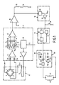
- the circuit comprises a horizontal magnetic field probe 6, a unit for processing the signal 7 and an amplifier 16 whose output controls a pair of compensation coils 15, arranged in series with one another, suitable for producing a component of an axial magnetic field opposite to that detected by the probe 6.
- the output of the amplifier 16 also controls a pair of demagnetization coils 17, arranged in parallel to one another, suitable for producing, in combination with a screen to be described later, a component of a lateral magnetic field opposite to the lateral component of the external field.
- a unit 18 for the detection of variations of a magnetic field
- a control unit 19 and a demagnetization circuit 20.
- the unit for processing the signal 7 also comprises a control unit 10 constituted essentially by an impulse generator driven by the set's vertical synchronisation signal to send alternately positive and negative impulses to the inversion coil 5 through a driving circuit 11 and simultaneously to control the alternate closing and opening of two pairs of switches 45, 47 and 44, 46 that select the signals transmitted to the non-inverting and inverting inputs 13, 14 of the differential amplifier 12.
- a control unit 10 constituted essentially by an impulse generator driven by the set's vertical synchronisation signal to send alternately positive and negative impulses to the inversion coil 5 through a driving circuit 11 and simultaneously to control the alternate closing and opening of two pairs of switches 45, 47 and 44, 46 that select the signals transmitted to the non-inverting and inverting inputs 13, 14 of the differential amplifier 12.
- the unit 18 for the detection of variations of magnetic fields comprises a whole-have rectifier shunt 28 which receives at input the output signal of the amplifier 16, that is, a signal having a voltage proportional to the variation of the horizontal magnetic field, and produces an output which is compared to a reference voltage Vrif by means of a comparator 29 to produce, in the end, a control impulse for the control unit 19.
- the latter is in turn constituted by a bistable multivibrator 30 that controls the demagnetization circuit 20 and by two timers 31, 32, the first of which has the function of determining the time of activation of the demagnetization circuit 20, while the second has the task of disactivating the output of the bistable multivibrator 30 for the time necessary for the demagnetization circuit 20 to recharge, while also allowing the control impulse of the circuit 20 to be memorized in it.
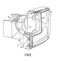
- the compensation circuit of Fig. 1 can be imagined to be applied to a picture tube 60 provided with a screen 63 and contained inside a shell 61. Inside it there is a mask 62 with holes to direct the electronic beams towards the coloured phosphoruses on the screen 63 and an internal magnetic screen 64. There is also a magnetic probe 6, a pair of compensation coils 15, arranged concentrically at the two extremities of the picture tube 60, suitable for producing an axial magnetic field and a pair of demagnetization coils 17 associated with the internal magnetic screen 64 for producing a lateral magnetic field, as illustrated in Fig. 1.
- the compensation circuit of Fig. 1 functions as follows.
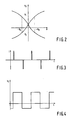
- the bridge circuit 1 - 4 has a pair of H-Vo characteristics (magnetic field detected in a produced voltage), which in themselves are a source of indetermination in relation to the sign of the variation detected in the horizontal magnetic field (Ho or -Ho).
- a succession of such alternately positive and negative impulses is sent by the control unit 10 through the driving circuit 11 to the inversion coil 5.
- Such impulses have the task of forcing the bridge of resistances 1, 2, 3, 4 to work alternately on one and on the other of the characteristics illustrated in Fig. 2.
- a square-wave signal illustrated in Fig. 4, whose curve is representative of the value and of the sign of the magnetic field under test. Any offset of said output signal is cancelled by the condensers 23 and 24.
- the impulses generated by the control unit 10 determine the periodic operation of switches 44, 45, 46, 47 in the signal switching unit 9, which thus makes the comparison between the square-wave signal from the probe 6, amplified by the preamplifier 8, and a reference signal Vref, applying the square-wave signal across the non-inverting input 13 of the differential amplifier 12 and the reference signal across the inverting input 14 of the same amplifier 12 when the square-wave signal has a positive sign and vice versa when the sign is negative.
- Such an operation has the effect of producing an output voltage that is continuous and proportional to the value of the magnetic field under test, which through the amplifier 16 shall supply the compensation coils 15 for the compensation of the axial magnetic field.
- the impulse from the control unit 19 controls the oscillation of the demagnetization circuit 20, Those duration is governed by the discharge time of the condenser 53, in turn charged by the current generator 55.
- the control signal for the demagnetization circuit 20 enters into the inverting input of the comparator 48, which through the power stage 49 sends into resonance the circuit consisting of the demagnetization coils 17 and the condenser 50.
- the feedback signal is picked up across the diode parallel 51, 54 and applied across the non-inverting input of the comparator 48.
- the oscillation of the circuit 20 stops to start again when the next control impulse arrives from the control unit 19.
Landscapes
- Engineering & Computer Science (AREA)
- Multimedia (AREA)
- Signal Processing (AREA)
- Physics & Mathematics (AREA)
- Electromagnetism (AREA)
- General Physics & Mathematics (AREA)
- Radar, Positioning & Navigation (AREA)
- Automation & Control Theory (AREA)
- Video Image Reproduction Devices For Color Tv Systems (AREA)
- Color Television Image Signal Generators (AREA)
- Manufacture Of Electron Tubes, Discharge Lamp Vessels, Lead-In Wires, And The Like (AREA)
- Vessels, Lead-In Wires, Accessory Apparatuses For Cathode-Ray Tubes (AREA)
Priority Applications (1)
| Application Number | Priority Date | Filing Date | Title |
|---|---|---|---|
| EP95201774A EP0676901A3 (fr) | 1990-06-08 | 1991-06-04 | Circuit de détection de champs magnétique. |
Applications Claiming Priority (2)
| Application Number | Priority Date | Filing Date | Title |
|---|---|---|---|
| IT02059490A IT1248761B (it) | 1990-06-08 | 1990-06-08 | Circuito di compensazione della componente orizzontale del campo magnetico terrestre per cinescopio a colori di monitor ad alta risoluzione |
| IT2059490 | 1990-06-08 |
Related Child Applications (1)
| Application Number | Title | Priority Date | Filing Date |
|---|---|---|---|
| EP95201774.7 Division-Into | 1991-06-04 |
Publications (3)
| Publication Number | Publication Date |
|---|---|
| EP0460757A2 true EP0460757A2 (fr) | 1991-12-11 |
| EP0460757A3 EP0460757A3 (en) | 1992-10-28 |
| EP0460757B1 EP0460757B1 (fr) | 1997-01-08 |
Family
ID=11169305
Family Applications (2)
| Application Number | Title | Priority Date | Filing Date |
|---|---|---|---|
| EP91201364A Expired - Lifetime EP0460757B1 (fr) | 1990-06-08 | 1991-06-04 | Dispositif d'affichage |
| EP95201774A Withdrawn EP0676901A3 (fr) | 1990-06-08 | 1991-06-04 | Circuit de détection de champs magnétique. |
Family Applications After (1)
| Application Number | Title | Priority Date | Filing Date |
|---|---|---|---|
| EP95201774A Withdrawn EP0676901A3 (fr) | 1990-06-08 | 1991-06-04 | Circuit de détection de champs magnétique. |
Country Status (7)
| Country | Link |
|---|---|
| US (1) | US5179315A (fr) |
| EP (2) | EP0460757B1 (fr) |
| JP (1) | JPH04233389A (fr) |
| KR (1) | KR920001950A (fr) |
| CA (1) | CA2043934C (fr) |
| DE (1) | DE69124011T2 (fr) |
| IT (1) | IT1248761B (fr) |
Cited By (3)
| Publication number | Priority date | Publication date | Assignee | Title |
|---|---|---|---|---|
| GB2317314A (en) * | 1996-09-13 | 1998-03-18 | Lg Electronics Inc | A purity adjustment device for a CRT display |
| EP0825785A3 (fr) * | 1996-08-22 | 1999-04-14 | Thomson Consumer Electronics, Inc. | Système de correction de bande décolorée |
| WO1999022526A1 (fr) * | 1997-10-24 | 1999-05-06 | Nagamori, Satoshi | Dispositif de correction du magnetisme terrestre et recepteur de television equipe d'un tel dispositif |
Families Citing this family (4)
| Publication number | Priority date | Publication date | Assignee | Title |
|---|---|---|---|---|
| JPH07162882A (ja) * | 1993-12-10 | 1995-06-23 | Sony Corp | 陰極線管装置 |
| JP3541468B2 (ja) * | 1994-12-15 | 2004-07-14 | ソニー株式会社 | 表示装置 |
| KR0182920B1 (ko) * | 1996-05-02 | 1999-10-01 | 김광호 | 이미지 로테이션 자동 보상 회로 및 보상 방법 |
| US8525514B2 (en) | 2010-03-19 | 2013-09-03 | Memsic, Inc. | Magnetometer |
Family Cites Families (13)
| Publication number | Priority date | Publication date | Assignee | Title |
|---|---|---|---|---|
| FR1600004A (fr) * | 1967-12-29 | 1970-07-20 | ||
| US3887833A (en) * | 1969-06-16 | 1975-06-03 | Hitachi Ltd | Color purity adjusting device for a color picture tube |
| US3757154A (en) * | 1971-03-03 | 1973-09-04 | Sony Corp | Magnetic field on color television receivers apparatus for automatically eliminating the influence of the earth s |
| JPS5137393Y2 (fr) * | 1971-10-28 | 1976-09-13 | ||
| US3757174A (en) * | 1972-07-31 | 1973-09-04 | Sharp Kk | Light emitting four layer semiconductor |
| DE3017331A1 (de) * | 1980-05-06 | 1981-11-12 | Siemens AG, 1000 Berlin und 8000 München | Anordnung zur kompensation von auf farbfernsehroehren einwirkenden magnetischen fremdfeldern |
| EP0065830A1 (fr) * | 1981-05-07 | 1982-12-01 | EMI Limited | Arrangement avec un élément sensible magnétorésistif |
| EP0074219B1 (fr) * | 1981-09-09 | 1985-11-27 | EMI Limited | Arrangement pour résoudre les composants d'un champ magnétique |
| US4380716A (en) * | 1981-10-09 | 1983-04-19 | Hazeltine Corporation | External magnetic field compensator for a CRT |
| DE3442278A1 (de) * | 1984-11-20 | 1986-05-22 | Philips Patentverwaltung Gmbh, 2000 Hamburg | Magnetfeldmessgeraet |
| US4636911A (en) * | 1984-11-30 | 1987-01-13 | Rca Corporation | Resonant degaussing for a video display system |
| US5036250A (en) * | 1988-06-14 | 1991-07-30 | U.S. Philips Corporation | Picture display device with core means comprising compensation coils |
| US4950955A (en) * | 1988-09-06 | 1990-08-21 | Rca Licensing Corporation | Magnetic field compensator for a CRT |
-
1990
- 1990-06-08 IT IT02059490A patent/IT1248761B/it active IP Right Grant
-
1991
- 1991-06-03 US US07/709,678 patent/US5179315A/en not_active Expired - Fee Related
- 1991-06-04 EP EP91201364A patent/EP0460757B1/fr not_active Expired - Lifetime
- 1991-06-04 EP EP95201774A patent/EP0676901A3/fr not_active Withdrawn
- 1991-06-04 DE DE69124011T patent/DE69124011T2/de not_active Expired - Fee Related
- 1991-06-05 CA CA002043934A patent/CA2043934C/fr not_active Expired - Fee Related
- 1991-06-06 JP JP3160837A patent/JPH04233389A/ja active Pending
- 1991-06-07 KR KR1019910009413A patent/KR920001950A/ko not_active Abandoned
Cited By (5)
| Publication number | Priority date | Publication date | Assignee | Title |
|---|---|---|---|---|
| EP0825785A3 (fr) * | 1996-08-22 | 1999-04-14 | Thomson Consumer Electronics, Inc. | Système de correction de bande décolorée |
| GB2317314A (en) * | 1996-09-13 | 1998-03-18 | Lg Electronics Inc | A purity adjustment device for a CRT display |
| GB2317314B (en) * | 1996-09-13 | 1998-12-30 | Lg Electronics Inc | Purity adjustment device for video display appliance |
| US6246448B1 (en) | 1996-09-13 | 2001-06-12 | L.G. Electronics, Inc. | Purity adjustment device for video display appliance |
| WO1999022526A1 (fr) * | 1997-10-24 | 1999-05-06 | Nagamori, Satoshi | Dispositif de correction du magnetisme terrestre et recepteur de television equipe d'un tel dispositif |
Also Published As
| Publication number | Publication date |
|---|---|
| EP0676901A3 (fr) | 1997-07-16 |
| DE69124011T2 (de) | 1997-06-19 |
| US5179315A (en) | 1993-01-12 |
| EP0460757A3 (en) | 1992-10-28 |
| CA2043934C (fr) | 2002-02-12 |
| JPH04233389A (ja) | 1992-08-21 |
| EP0460757B1 (fr) | 1997-01-08 |
| KR920001950A (ko) | 1992-01-30 |
| IT9020594A1 (it) | 1991-12-08 |
| EP0676901A2 (fr) | 1995-10-11 |
| CA2043934A1 (fr) | 1991-12-09 |
| IT9020594A0 (fr) | 1990-06-08 |
| IT1248761B (it) | 1995-01-27 |
| DE69124011D1 (de) | 1997-02-20 |
Similar Documents
| Publication | Publication Date | Title |
|---|---|---|
| US4963789A (en) | Method and apparatus for dynamic magnetic field neutralization | |
| US4485394A (en) | Automatic convergence and gray scale correction for television _receivers and projection television systems | |
| US5179315A (en) | Circuit for the compensation of the horizontal component of the earth's magnetic field for a color picture tube of a high-resolution monitor | |
| US7330164B2 (en) | Video controlled detector sensitivity | |
| US5367221A (en) | Magnetic immunity system (MIS) and monitor incorporating the MIS | |
| DK147330B (da) | Fremgangsmaade og apparat til ved magnetisering at opnaa statisk konvergens i et katodestraaleroer | |
| KR0144731B1 (ko) | 자계 보상기 장치 | |
| US5604403A (en) | Color monitor magnetic shield | |
| ES472785A1 (es) | Un aparato de presentacion de television en colores | |
| JPH0411076B2 (fr) | ||
| KR100319063B1 (ko) | 음극선관장치 | |
| HK25096A (en) | Method and device for adjusting static convergence and/or purity for a colour television tube | |
| GB818669A (en) | Presentation of coloured television pictures | |
| US3737716A (en) | Color purity adjustment utilizing a coil attached to the faceplate | |
| SU1345149A1 (ru) | Устройство дл намагничивани , размагничивани и контрол напр женности магнитного пол изделий | |
| US2806978A (en) | Alignment of television camera tubes | |
| KR19990082246A (ko) | 음극선관내에서 정적 컨버젼스 교정을 하기 위해 자기링을자기화시키는 장치와 과정 | |
| JPS59148484A (ja) | カラ−受像装置の消磁装置 | |
| JP2845906B2 (ja) | 色純度測定装置および方法 | |
| US7286175B1 (en) | Bias control circuitry for cathode ray tube beam currents | |
| US6635994B1 (en) | Method and apparatus for demagnetizing color CRT | |
| JP3250287B2 (ja) | 陰極線管のビームスポットの位置ずれの測定方法及び測定装置 | |
| KR910010118B1 (ko) | 직류전원을 이용한 브라운관 소자회로 | |
| JPH0156594B2 (fr) | ||
| SU1401650A1 (ru) | Устройство дл отображени информации на экране цветной электронно-лучевой трубки |
Legal Events
| Date | Code | Title | Description |
|---|---|---|---|
| PUAI | Public reference made under article 153(3) epc to a published international application that has entered the european phase |
Free format text: ORIGINAL CODE: 0009012 |
|
| AK | Designated contracting states |
Kind code of ref document: A2 Designated state(s): DE FR GB IT |
|
| PUAL | Search report despatched |
Free format text: ORIGINAL CODE: 0009013 |
|
| AK | Designated contracting states |
Kind code of ref document: A3 Designated state(s): DE FR GB IT |
|
| 17P | Request for examination filed |
Effective date: 19930421 |
|
| 17Q | First examination report despatched |
Effective date: 19931112 |
|
| GRAG | Despatch of communication of intention to grant |
Free format text: ORIGINAL CODE: EPIDOS AGRA |
|
| RTI1 | Title (correction) | ||
| GRAH | Despatch of communication of intention to grant a patent |
Free format text: ORIGINAL CODE: EPIDOS IGRA |
|
| GRAH | Despatch of communication of intention to grant a patent |
Free format text: ORIGINAL CODE: EPIDOS IGRA |
|
| GRAA | (expected) grant |
Free format text: ORIGINAL CODE: 0009210 |
|
| AK | Designated contracting states |
Kind code of ref document: B1 Designated state(s): DE FR GB IT |
|
| XX | Miscellaneous (additional remarks) |
Free format text: TEILANMELDUNG 95201774.7 EINGEREICHT AM 04/06/91. |
|
| REF | Corresponds to: |
Ref document number: 69124011 Country of ref document: DE Date of ref document: 19970220 |
|
| ITF | It: translation for a ep patent filed | ||
| ET | Fr: translation filed | ||
| PLBE | No opposition filed within time limit |
Free format text: ORIGINAL CODE: 0009261 |
|
| STAA | Information on the status of an ep patent application or granted ep patent |
Free format text: STATUS: NO OPPOSITION FILED WITHIN TIME LIMIT |
|
| 26N | No opposition filed | ||
| REG | Reference to a national code |
Ref country code: FR Ref legal event code: CD |
|
| PGFP | Annual fee paid to national office [announced via postgrant information from national office to epo] |
Ref country code: FR Payment date: 20010625 Year of fee payment: 11 |
|
| PGFP | Annual fee paid to national office [announced via postgrant information from national office to epo] |
Ref country code: GB Payment date: 20010629 Year of fee payment: 11 |
|
| PGFP | Annual fee paid to national office [announced via postgrant information from national office to epo] |
Ref country code: DE Payment date: 20010821 Year of fee payment: 11 |
|
| REG | Reference to a national code |
Ref country code: GB Ref legal event code: IF02 |
|
| PG25 | Lapsed in a contracting state [announced via postgrant information from national office to epo] |
Ref country code: GB Free format text: LAPSE BECAUSE OF NON-PAYMENT OF DUE FEES Effective date: 20020604 |
|
| PG25 | Lapsed in a contracting state [announced via postgrant information from national office to epo] |
Ref country code: DE Free format text: LAPSE BECAUSE OF NON-PAYMENT OF DUE FEES Effective date: 20030101 |
|
| GBPC | Gb: european patent ceased through non-payment of renewal fee |
Effective date: 20020604 |
|
| PG25 | Lapsed in a contracting state [announced via postgrant information from national office to epo] |
Ref country code: FR Free format text: LAPSE BECAUSE OF NON-PAYMENT OF DUE FEES Effective date: 20030228 |
|
| REG | Reference to a national code |
Ref country code: FR Ref legal event code: ST |
|
| PG25 | Lapsed in a contracting state [announced via postgrant information from national office to epo] |
Ref country code: IT Free format text: LAPSE BECAUSE OF NON-PAYMENT OF DUE FEES;WARNING: LAPSES OF ITALIAN PATENTS WITH EFFECTIVE DATE BEFORE 2007 MAY HAVE OCCURRED AT ANY TIME BEFORE 2007. THE CORRECT EFFECTIVE DATE MAY BE DIFFERENT FROM THE ONE RECORDED. Effective date: 20050604 |