EP0461341A1 - Hebebühne für Kraftfahrzeuge - Google Patents
Hebebühne für Kraftfahrzeuge Download PDFInfo
- Publication number
- EP0461341A1 EP0461341A1 EP91102414A EP91102414A EP0461341A1 EP 0461341 A1 EP0461341 A1 EP 0461341A1 EP 91102414 A EP91102414 A EP 91102414A EP 91102414 A EP91102414 A EP 91102414A EP 0461341 A1 EP0461341 A1 EP 0461341A1
- Authority
- EP
- European Patent Office
- Prior art keywords
- lifting
- support tube
- columns
- lifting platform
- platform according
- Prior art date
- Legal status (The legal status is an assumption and is not a legal conclusion. Google has not performed a legal analysis and makes no representation as to the accuracy of the status listed.)
- Granted
Links
Images


Classifications
-
- B—PERFORMING OPERATIONS; TRANSPORTING
- B66—HOISTING; LIFTING; HAULING
- B66F—HOISTING, LIFTING, HAULING OR PUSHING, NOT OTHERWISE PROVIDED FOR, e.g. DEVICES WHICH APPLY A LIFTING OR PUSHING FORCE DIRECTLY TO THE SURFACE OF A LOAD
- B66F7/00—Lifting frames, e.g. for lifting vehicles; Platform lifts
- B66F7/10—Lifting frames, e.g. for lifting vehicles; Platform lifts with platforms supported directly by jacks
- B66F7/16—Lifting frames, e.g. for lifting vehicles; Platform lifts with platforms supported directly by jacks by one or more hydraulic or pneumatic jacks
- B66F7/20—Lifting frames, e.g. for lifting vehicles; Platform lifts with platforms supported directly by jacks by one or more hydraulic or pneumatic jacks by several jacks with means for maintaining the platforms horizontal during movement
Definitions
- the invention relates to a lifting platform for motor vehicles, in particular passenger cars, with at least two vertically movable columns which have a support surface at the top for receiving the vehicle, the columns being arranged underground in a pit in the retracted state and the support surface being approximately at the level of the workshop floor .
- the present invention has for its object to improve a built-in lift in the workshop floor of the type described in such a way that it manages with a lower pit depth at the same lifting height.
- the lifting platform according to the invention should be characterized by a robust and inexpensive construction.
- the lifting element By connecting the support tube with the traction means, which in turn runs over a deflecting roller of the lifting element, the lifting element generates a stroke path of the support tube which is twice as large when it is started up. At the same time, the guide of the support tube is continuously shifted upward by the movable sleeve, so that the support tube is stabilized in the transverse direction even in the extended state.
- the invention consists essentially in the combination of the lift reinforcement with the telescopic guide.
- the movable sleeve which acts as a telescopic guide for the support tube, can be arranged inside or outside the same. It expediently surrounds the support tube on the outside thereof and is in turn guided in a guide bush which is embedded in the workshop floor.
- the movement of the sleeve can be produced by the support tube, for example in such a way that the support tube comes into contact with the sleeve after reaching half the lift height and takes it along during the rest of the stroke .
- the sleeve is rigidly connected to the lifting element and carries out the lifting movements synchronously with it.
- the lift can have four columns, which are connected in pairs via entry rails for the vehicle. In practice, however, it is sufficient if only two pillars are provided, one on each side of the vehicle. In this case, it is particularly expedient if an anti-rotation device is attached between the support tube and the lifting element.
- the support tube can have a guide plate surrounding the lifting element near its lower end, the central opening of which corresponds to the outer contour of the lifting element.
- the lifting force is introduced into the columns either directly on the lifting elements or via the common transverse yoke.
- the lifting elements can be part of a hydraulically actuated cylinder-piston unit.
- the transverse yoke can be made using lifting spindles or a scissor-type frame.
- the lifting platform is in the lowered state.
- the two support surfaces 1a and 1b which serve to accommodate the vehicle, are located on the same Level as the workshop floor 2.
- Their two pillars which are generally designated 3a and 3b, stand on the foundation 5 of a pit 6.
- a lifting element 7a or 7b in the form of a cylinder-piston unit, the piston rod 8a or 8b of which carries a deflecting roller 9a or 9b at the upper end and moves it hydraulically upwards can be.
- a traction means 10a or 10b in the form of a chain or a rope runs over the deflection roller.
- This traction means is fixed at one end, for example on the foundation or on the cylinder of the lifting element 7a, 7b, while the opposite other end is connected to the lower region of a support tube 11a or 11b.
- the aforementioned support surface 1a or 1b is mounted on this support tube.
- a second traction means with its own deflection roller is arranged in each column at a short distance from each other and this traction means acts on the opposite side of the first traction means.
- the sleeve is connected directly or indirectly to the part of the lifting element that moves upwards, that is to say here to the piston 8a or 8b.
- the piston rod 8a or 8b has for this purpose a downward extension 13a or 13b, which is connected to the sleeve 12a or 12b near the lower end of the support tube 11a, in the exemplary embodiment by means of a transverse yoke 14 which the two reciprocating pistons 8a and 8b and the sleeves 11a and 11b connected to them are synchronized.
- the two sleeves each run in a guide bush 15a or 15b, which is embedded in the workshop floor.
- the length of the sleeves corresponds approximately to the travel of the piston rods 8a and 8b and thus approximately half the stroke of the support tubes 11a and 11b.
- the mode of operation is as follows: If the lifting elements 7a and 7b are pressurized with oil, the piston rods 8a and 8b and, at the same speed, the two sleeves 12a and 12b move upwards. At the same time, but at twice the lifting speed, the support tubes 11a and 11b are raised by the traction means 10a and 10b running over the deflection rollers. By giving them half speed Following sleeves 12a and 12b, the guide for the support tubes is shifted upwards, ie that the support tube is supported by the sleeve at about half the height of the extended stroke length.
- guide rings 16a or 16b are provided between the support tube 11a or 11b and its sleeve 12a or 12b, in the form of two rings arranged one above the other at a distance. This prevents a tilting game between the two parts.
- These guide rings can be positioned at the lower end of the support tube or at the upper end of the sleeve.
- Sealing ring pairs 17a and 17b between the sleeve and its guide bushing 15a and 15b serve the same purpose.
- an anti-rotation device in the form of a plate 18a, which forms the lower end of the support tube 11a, to which the traction means 10a is anchored and which has an opening 19a with a square cross-section, matching the contour of the downward extension 13a of the piston rod 8a.
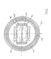
- Figure 3 shows a cross section at the level of the guide rollers. It can be seen here that in each column there are two deflecting rollers 9a and 9a 'arranged next to one another, each of which is assigned a separate traction means 10a or 10a'. These traction means are arranged in opposite directions, so that their ends performing the lifting movement act on approximately opposite regions of the support tube 11a.
- the described invention is characterized by a small installation depth without restriction of the lifting height and by exact guidance of the support tubes in their raised position.
Landscapes
- Life Sciences & Earth Sciences (AREA)
- Engineering & Computer Science (AREA)
- Geology (AREA)
- Mechanical Engineering (AREA)
- Structural Engineering (AREA)
- Types And Forms Of Lifts (AREA)
- Conveying And Assembling Of Building Elements In Situ (AREA)
- Vehicle Cleaning, Maintenance, Repair, Refitting, And Outriggers (AREA)
- Reciprocating, Oscillating Or Vibrating Motors (AREA)
- Carriers, Traveling Bodies, And Overhead Traveling Cranes (AREA)
Abstract
Description
- Die Erfindung betrifft eine Hebebühne für Kraftfahrzeuge, insbesondere Personenwagen, mit mindestens zwei vertikal verfahrbaren Säulen, die oben eine Stützfläche zur Aufnahme des Fahrzeuges aufweisen, wobei die Säulen in eingefahrenem Zustand unterirdisch in einer Grube angeordnet sind und die Stützfläche etwa auf dem Niveau des Werkstattbodens liegt.
- Derartige Hebebühnen sind in verschiedenen Bauformen bekannt. Ihr Vorteil liegt darin, daß in eingefahrenem Zustand alle Teile der Hebebühne im Werkstattboden verschwinden. Dadurch ist die Bewegungsfreiheit in der Werkstatt wesentlich besser als bei den oberirdischen Hebebühnen, deren Säulen auch dann im Weg stehen, wenn die Bühne nicht benutzt wird.
- Andererseits ist es für die in den Hallenboden eingebauten Hebebühnen notwendig, Gruben auszuheben, die eine Tiefe aufweisen müssen, die etwa der Hubhöhe der Bühne entspricht. Hierfür müssen in der Praxis Gruben mit einer Tiefe von etwa 2 m ausgehoben werden.
- Der vorliegenden Erfindung liegt die Aufgabe zugrunde, eine in den Werkstattboden einbaubare Hebebühne der eingangs beschriebenen Art dahingehend zu verbessern, daß sie bei gleicher Hubhöhe mit einer geringeren Grubentiefe auskommt. Außerdem soll sich die erfindungsgemäße Hebebühne durch robusten und kostengünstigen Aufbau auszeichnen.
- Diese Aufgabe wird erfindungsgemäß dadurch gelöst, daß die Säulen jeweils folgenden Aufbau aufweisen:
- a) ein inneres vertikal verfahrbares Hubelement, daß am oberen Ende eine Umlenkrolle für ein zumindest teilweise flexibles Zugmittel trägt, dessen eines Ende ortsfest montiert ist,
- b) ein gegenüber dem Hubelement vertikal verfahrbares Tragrohr, daß oben die Stützfläche trägt und unten mit dem anderen Ende des Zugmittels verbunden ist und
- c) eine relativ zum Tragrohr verfahrbare Hülse, die beim Ausfahren der Säule als Teleskopführung für das Tragrohr fungiert.
- Durch die Verbindung des Tragrohres mit dem Zugmittel, das seinerseits über eine Umlenkrolle des Hubelementes läuft, erzeugt das Hubelement beim Hochfahren in an sich bekannter Weise einen doppelt so großen Hubweg des Tragrohres. Zugleich wird durch die verfahrbare Hülse die Führung des Tragrohres laufend nach oben verlagert, so daß das Tragrohr auch in ausgefahrenem Zustand in Querrichtung stabilisiert ist. Die Erfindung besteht also im wesentlichen in der Kombination der Hubverstärkung mit der Teleskopführung.
- Die verfahrbare Hülse, die als Teleskopführung für das Tragrohr fungiert, kann innerhalb oder außerhalb desselben angeordnet sein. Zweckmäßig umgibt sie das Tragrohr an dessen Außenseite und ist ihrerseits in einer Führungsbuchse, die im Werkstattboden eingelassen ist, geführt.
- Das Verfahren der Hülse, deren Hub etwa dem halben Hub des Tragrohres entspricht, kann vom Tragrohr erzeugt werden, etwa in der Weise, daß das Tragrohr nach Erreichen der halben Hubhöhe mit einem Anschlag in Anlage mit der Hülse gelangt und sie während des restlichen Hubweges mitnimmt. Besonders günstig ist es indessen, wenn die Hülse starr mit dem Hubelement verbunden ist und synchron mit ihm die Hubbewegungen durchführt.
- Theoretisch kann die Hebebühne vier Säulen aufweisen, die paarweise über Einfahrschienen für das Fahrzeug verbunden sind. In der Praxis ist es jedoch ausreichend, wenn nur zwei Säulen vorgesehen sind, eine an jeder Fahrzeugseite. In diesem Fall ist es besonders zweckmäßig, wenn zwischen Tragrohr und Hubelement eine Verdrehsicherung angebracht ist. Zu diesem Zweck kann das Tragrohr nahe seinem unteren Ende eine das Hubelement umgebende Führungsplatte aufweisen, deren zentrale Öffnung mit der Außenkontur des Hubelementes korrespondiert.
- Damit beide Säulen die Hubbewegung synchron durchführen, empfiehlt es sich, beide Säulen durch ein Querjoch miteinander zu verbinden, das mit seinen Enden an den beiden Hubelementen und/oder den beiden Hülsen festgelegt ist.
- Die Einleitung der Hubkraft in die Säulen erfolgt entweder direkt an den Hubelementen oder über das gemeinsame Querjoch. Im erstgenannten Fall können die Hubelemente Teil eines hydraulisch betätigbaren Zylinder-Kolben-Aggregates sein. Im zweiten Fall kann das Querjoch etwa durch Hubspindeln oder ein Scheren-Gestell.
- Weitere Merkmale und Vorteile der Erfindung ergeben sich aus nachfolgender Beschreibung eines Ausführungsbeispieles anhand der Zeichnung; dabei zeigt
- Figur 1 eine schematische Prinzipdarstellung der Hebebühne;
- Figur 2 einen vergrößerten Längsschnitt einer Säule und
- Figur 3 einen Querschnitt durch Figur 2.
- In der Prinzipdarstellung in Figur 1 befindet sich die Hebebühne in heruntergefahrenem Zustand. Dabei befinden sich die beiden Stützflächen 1a und 1b, die zur Aufnahme des Fahrzeuges dienen, auf dem selben Niveau wie der Werkstattboden 2. Ihre beiden Säulen, die allgemein mit 3a und 3b bezeichnet sind, stehen auf dem Fundament 5 einer Grube 6.
- Der Aufbau dieser Säulen ist folgender: In ihrem Zentrum steht ein Hubelement 7a bzw. 7b in Form eines Zylinder-Kolben-Aggregates, dessen Kolbenstange 8a bzw. 8b am oberen Ende jeweils eine Umlenkrolle 9a bzw. 9b trägt und mit dieser hydraulisch nach oben verfahren werden kann.
- Über die Umlenkrolle läuft jeweils ein Zugmittel 10a bzw. 10b in Form einer Kette oder eines Seiles. Dieses Zugmittel ist mit seinem einen Ende ortsfest, beispielsweise am Fundament oder am Zylinder des Hubelementes 7a, 7b festgelegt, während das gegenüberliegende andere Ende mit dem unteren Bereich eines Tragrohres 11a bzw. 11b verbunden ist. Auf diesem Tragrohr ist die vorerwähnte Stützfläche 1a bzw. 1b montiert.
- Damit das Zugmittel nicht nur einseitig am Tragrohr angreift, ist jeweils in geringem Abstand parallel hierzu ein zweites Zugmittel mit einer eigenen Umlenkrolle in jeder Säule angeordnet und dieses Zugmittel greift an der gegenüberliegenden Seite des ersten Zugmittels an.
- Wesentlich ist nun, daß das Tragrohr 11a bzw. 11b während seiner Hubbewegung von einer ebenfalls verfahrbaren Hülse 12a bzw. 12b in Querrichtung abgestützt wird, so daß diese Hülse als Teleskopführung für das Tragrohr fungiert.
- Die Hülse ist direkt oder indirekt mit dem nach oben fahrenden Teil des Hubelementes, hier also mit dem Kolben 8a bzw. 8b, verbunden. Im Ausführungsbeispiel weist die Kolbenstange 8a bzw. 8b zu diesem Zweck eine nach unten gezogene Verlängerung 13a bzw. 13b auf, die nahe dem unteren Ende des Tragrohres 11a mit der Hülse 12a bzw. 12b in Verbindung steht, im Ausführungsbeispiel mittels eines Querjoches 14, das die beiden Hubkolben 8a bzw. 8b und die damit verbundenen Hülsen 11a bzw. 11b synchronisiert.
- Am oberen Ende laufen die beiden Hülsen jeweils in einer Führungsbuchse 15a bzw. 15b, die im Werkstattboden eingelassen ist. Die Länge der Hülsen entspricht etwa dem Verfahrweg der Kolbenstangen 8a bzw. 8b und somit etwa dem halben Hub der Tragrohre 11a und 11b.
- Die Wirkungsweise ist folgende: Werden die Hubelemente 7a und 7b mit Drucköl beaufschlagt, so fahren die Kolbenstangen 8a und 8b und mit gleicher Geschwindigkeit auch die beiden Hülsen 12a und 12b nach oben. Gleichzeitig, aber mit doppelter Hubgeschwindigkeit werden die Tragrohre 11a und 11b von den dabei über die Umlenkrollen laufenden Zugmitteln 10a und 10b angehoben. Durch die ihnen mit halber Geschwindigkeit folgenden Hülsen 12a und 12b wird die Führung für die Tragrohre nach oben verlagert, d. h., daß das Tragrohr jeweils etwa auf der halben Höhe der ausgefahrenen Hublänge durch die Hülse abgestützt wird.
- Zweckmäßigerweise sind zwischen dem Tragrohr 11a bzw. 11b und seiner Hülse 12a bzw. 12b Führungsringe 16a bzw. 16b vorgesehen, und zwar in Form zweier mit Abstand übereinander angeordneter Ringe. Dadurch wird ein Kippspiel zwischen beiden Teilen ausgeschlossen. Diese Führungsringe können am unteren Ende des Tragrohres oder am oberen Ende der Hülse positioniert sein.
- Zum gleichen Zweck dienen Dichtungsringpaare 17a bzw. 17b zwischen der Hülse und ihrer Führungsbuchse 15a bzw. 15b.
- Weitere Merkmale der Konstruktion ergeben sich aus den nachfolgenden Figuren.
- Man erkennt insbesondere in Figur 2 eine Verdrehsicherung in Form einer Platte 18a, die den unteren Abschluß des Tragrohres 11a bildet, an der das Zugmittel 10a verankert ist und die innen eine Öffnung 19a mit viereckigem Querschnitt aufweist, passend zu der Kontur der nach unten laufenden Verlängerung 13a der Kolbenstange 8a.
- Figur 3 zeigt einen Querschnitt in Höhe der Umlenkrollen. Man erkennt hier, daß in jeder Säule zwei nebeneinander angeordnete Umlenkrollen 9a und 9a' angeordnet sind, denen jeweils ein seperates Zugmittel 10a bzw. 10a' zugeordnet ist. Diese Zugmittel sind gegenläufig angeordnet, so daß ihre die Hubbewegung durchführenden Enden an etwa gegenüberliegenden Bereichen des Tragrohres 11a angreifen.
- Zusammenfassend zeichnet sich die beschriebene Erfindung durch geringe Einbautiefe ohne Einschränkung der Hubhöhe und durch exakte Führung der Tragrohre in ihrer hochgefahrenen Position aus.
Claims (12)
- Hebebühne für Kraftfahrzeuge, insbesondere Personenwagen mit mindestens zwei vertikal verfahrbaren Säulen (3a, 3b), die oben eine Stützfläche (1a, 1b) zur Aufnahme des Fahrzeuges aufweisen, wobei die Säulen in eingefahrenem Zustand unterirdisch in einer Grube (6) angeordnet sind und die Stützflächen (1a, 1b) etwa auf dem Niveau des Werkstattbodens (2) liegen,
dadurch gekennzeichnet,
daß die Säulen jeweils folgenden Aufbau aufweisen:a) ein inneres vertikal verfahrbares Hubelement (7a, 7b, 8a, 8b), das am oberen Ende eine Umlenkrolle (9a, 9b) für ein zumindest teilweise flexibles Zugmittel (10a, 10b) trägt, dessen eines Ende ortsfest montiert ist,b) ein gegenüber dem Hubelement (7a, 7b, 8a, 8b) vertikal verfahrbares Tragrohr (11a, 11b), das oben die Stützfläche (1a, 1b) trägt und unten mit dem anderen Ende des Zugmittels (10a, 10b) verbunden ist,c) eine relativ zum Tragrohr (11a, 11b) verfahrbare Hülse (12a, 12b), die beim Ausfahren der Säule als Teleskopführung für das Tragrohr (11a, 11b) fungiert. - Hebebühne nach Anspruch 1,
dadurch gekennzeichnet,
daß die als Teleskopführung fungierende Hülse (12a, 12b) das Tragrohr (11a, 11b) an dessen Außenseite umgibt und die Hülse ihrerseits in einer Führungsbuchse (15a, 15b) etwa in Höhe des Werkstattbodens (2) geführt ist. - Hebebühne nach Anspruch 1 oder 2,
dadurch gekennzeichnet,
daß die Hülse (12a, 12b) starr mit dem Hubelement (8a, 8b) verbunden ist. - Hebebühne nach einem der vorhergehenden Ansprüche, wobei in beiden Fahrzeugseiten jeweils nur eine Säule (3a, 3b) zugeordnet ist,
dadurch gekennzeichnet,
daß zwischen Tragrohr (11a, 11b) und Hubelement (7a, 7b, 8a, 8b) eine Verdrehsicherung (18a) angebracht ist. - Hebebühne nach einem der vorhergehenden Ansprüche,
dadurch gekennzeichnet,
daß in jeder Säule (3a, 3b) zwei Zugmittel (10a, 10b) eingebaut sind, die an etwa gegenüberliegenden Stellen des Tragrohres (11a, 11b) angreifen. - Hebebühne nach einem der vorhergehenden Ansprüche,
dadurch gekennzeichnet,
daß das Tragrohr (11a, 11b) nahe seinem unteren Ende eine das Hubelement (7a, 7b, 8a, 8b) umgebende Führungsplatte (18a) als Verdrehsicherung aufweist. - Hebebühne nach einem der vorhergehenden Ansprüche,
dadurch gekennzeichnet,
daß beide Säulen (3a, 3b) zur Synchronisierung ihrer Hubbewegung mit einander verbunden sind. - Hebebühne nach Anspruch 7,
dadurch gekennzeichnet,
daß die Verbindung durch ein Querjoch (14) erfolgt, das starr mit den beiden Hubelementen (7a, 7b) verbunden ist. - Hebebühne nach Anspruch 8,
dadurch gekennzeichnet,
daß an dem Querjoch (14) sowohl die beiden Hubelemente (7a, 8a) als auch die beiden Hülsen (12a, 12b) festgelegt sind. - Hebebühne nach Anspruch 8 oder 9,
dadurch gekennzeichnet,
daß die Einleitung der Hubkraft an dem Querjoch (14) erfolgt. - Hebebühne nach einem der Ansprüche 1 bis 9,
dadurch gekennzeichnet,
daß das Hubelement (7a, 7b, 8a, 8b) ein hydraulisch betätigbares Zylinder-Kolben-Aggregat ist mit einer nach oben verfahrbaren Kolbenstange (8a, 8b). - Hebebühne nach einem der Ansprüche 1 bis 9,
dadurch gekennzeichnet,
daß das Hubelement (7a, 7b, 8a, 8b) ein hydraulisches Zylinder-Kolben-Aggregat ist, dessen Zylinder nach oben verfahrbar ist, wogegen sich die Kolbenstange auf dem Fundament abstützt.
Applications Claiming Priority (2)
| Application Number | Priority Date | Filing Date | Title |
|---|---|---|---|
| DE4018726 | 1990-06-12 | ||
| DE4018726A DE4018726A1 (de) | 1990-06-12 | 1990-06-12 | Hebebuehne fuer kraftfahrzeuge |
Publications (2)
| Publication Number | Publication Date |
|---|---|
| EP0461341A1 true EP0461341A1 (de) | 1991-12-18 |
| EP0461341B1 EP0461341B1 (de) | 1994-06-01 |
Family
ID=6408225
Family Applications (1)
| Application Number | Title | Priority Date | Filing Date |
|---|---|---|---|
| EP91102414A Expired - Lifetime EP0461341B1 (de) | 1990-06-12 | 1991-02-20 | Hebebühne für Kraftfahrzeuge |
Country Status (5)
| Country | Link |
|---|---|
| US (1) | US5129483A (de) |
| EP (1) | EP0461341B1 (de) |
| JP (1) | JPH04226298A (de) |
| AT (1) | ATE106359T1 (de) |
| DE (2) | DE4018726A1 (de) |
Cited By (2)
| Publication number | Priority date | Publication date | Assignee | Title |
|---|---|---|---|---|
| EP0898033A1 (de) * | 1997-08-22 | 1999-02-24 | Otto Nussbaum GmbH & Co. KG | Transport- und Lagereinrichtung, insbesondere für Kraftfahrzeuge |
| CN107381343A (zh) * | 2017-08-29 | 2017-11-24 | 江汉大学 | 一种自行走式龙门升降装置 |
Families Citing this family (6)
| Publication number | Priority date | Publication date | Assignee | Title |
|---|---|---|---|---|
| US5339925A (en) * | 1993-11-23 | 1994-08-23 | Price Raymond D | Hydraulic chain lift |
| DE102009014719B4 (de) * | 2009-03-27 | 2019-06-13 | Maha Maschinenbau Haldenwang Gmbh & Co. Kg | Säulenhebebühne für Kraftfahrzeuge |
| CN105347143B (zh) * | 2015-11-27 | 2018-07-03 | 东南电梯股份有限公司 | 一种无导轨液压升降平台及升降方法 |
| DE202018107407U1 (de) | 2017-12-28 | 2019-03-29 | Klaus Multiparking Gmbh | Vorrichtung zum Abstellen von Fahrzeugen |
| CN108128723B (zh) * | 2017-12-31 | 2019-10-01 | 正潮建设工程有限公司 | 一种水利工程建坝用升降设备 |
| CN114162746B (zh) * | 2021-12-28 | 2023-03-21 | 中国建筑第二工程局有限公司 | 一种建筑施工用临时物品举升平台及其施工方法 |
Citations (5)
| Publication number | Priority date | Publication date | Assignee | Title |
|---|---|---|---|---|
| US3536162A (en) * | 1968-01-25 | 1970-10-27 | Autoquip Corp | "u" frame hydraulic vehicle lift |
| FR2340270A2 (fr) * | 1976-02-04 | 1977-09-02 | Vogler Walter | Dispositif de levage comportant un support de securite notamment pour le levage de vehicules |
| GB2146616A (en) * | 1983-09-14 | 1985-04-24 | Finkbeiner W | Lifting jack |
| US4892028A (en) * | 1984-09-10 | 1990-01-09 | Vbm Corporation | Fluid operated circuit for controlling a dual post hydraulic lift assembly |
| DE3836903C1 (de) * | 1988-10-29 | 1990-02-22 | Maschinenfabrik J.A. Becker U. Soehne Neckarsulm Gmbh & Co Kg, 7107 Neckarsulm, De |
Family Cites Families (9)
| Publication number | Priority date | Publication date | Assignee | Title |
|---|---|---|---|---|
| DE145189C (de) * | ||||
| US1886253A (en) * | 1930-02-24 | 1932-11-01 | Standard Lift Company | Multiple plunger lift |
| DE1141428B (de) * | 1958-09-10 | 1962-12-20 | Helmut Rudolph | Hydraulische Hebebuehne mit mehreren Teleskop-Hohlkolben |
| US3489248A (en) * | 1968-01-25 | 1970-01-13 | Autoquip Corp | U-frame hydraulic vehicle lift |
| DE2307711A1 (de) * | 1973-02-16 | 1974-08-22 | Emil Drestler | Hebebuehne fuer kraftfahrzeuge |
| US4134475A (en) * | 1977-06-20 | 1979-01-16 | Dura Corporation | Adjustable pad hydraulic lift |
| US4196887A (en) * | 1977-12-28 | 1980-04-08 | Yasui Sangyo Co., Ltd. | Vehicle support |
| DE3235829A1 (de) * | 1982-09-28 | 1984-03-29 | Kirner Auto-Präzision Robert Fuchs GmbH & Co KG, 6570 Kirn | Hebebuehne fuer fahrzeuge, insbesondere personenkraftwagen |
| DE9003685U1 (de) * | 1990-03-29 | 1990-06-07 | Franz Hörnstein GmbH & Co. KG, 7100 Heilbronn | Hebebühne für Kraftfahrzeuge |
-
1990
- 1990-06-12 DE DE4018726A patent/DE4018726A1/de not_active Withdrawn
-
1991
- 1991-02-20 EP EP91102414A patent/EP0461341B1/de not_active Expired - Lifetime
- 1991-02-20 AT AT91102414T patent/ATE106359T1/de not_active IP Right Cessation
- 1991-02-20 DE DE59101766T patent/DE59101766D1/de not_active Expired - Fee Related
- 1991-05-02 US US07/695,050 patent/US5129483A/en not_active Expired - Fee Related
- 1991-06-11 JP JP3138916A patent/JPH04226298A/ja active Pending
Patent Citations (5)
| Publication number | Priority date | Publication date | Assignee | Title |
|---|---|---|---|---|
| US3536162A (en) * | 1968-01-25 | 1970-10-27 | Autoquip Corp | "u" frame hydraulic vehicle lift |
| FR2340270A2 (fr) * | 1976-02-04 | 1977-09-02 | Vogler Walter | Dispositif de levage comportant un support de securite notamment pour le levage de vehicules |
| GB2146616A (en) * | 1983-09-14 | 1985-04-24 | Finkbeiner W | Lifting jack |
| US4892028A (en) * | 1984-09-10 | 1990-01-09 | Vbm Corporation | Fluid operated circuit for controlling a dual post hydraulic lift assembly |
| DE3836903C1 (de) * | 1988-10-29 | 1990-02-22 | Maschinenfabrik J.A. Becker U. Soehne Neckarsulm Gmbh & Co Kg, 7107 Neckarsulm, De |
Cited By (2)
| Publication number | Priority date | Publication date | Assignee | Title |
|---|---|---|---|---|
| EP0898033A1 (de) * | 1997-08-22 | 1999-02-24 | Otto Nussbaum GmbH & Co. KG | Transport- und Lagereinrichtung, insbesondere für Kraftfahrzeuge |
| CN107381343A (zh) * | 2017-08-29 | 2017-11-24 | 江汉大学 | 一种自行走式龙门升降装置 |
Also Published As
| Publication number | Publication date |
|---|---|
| DE59101766D1 (de) | 1994-07-07 |
| JPH04226298A (ja) | 1992-08-14 |
| US5129483A (en) | 1992-07-14 |
| DE4018726A1 (de) | 1992-01-02 |
| EP0461341B1 (de) | 1994-06-01 |
| ATE106359T1 (de) | 1994-06-15 |
Similar Documents
| Publication | Publication Date | Title |
|---|---|---|
| DE29824453U1 (de) | Kran mit einem Teleskopausleger | |
| DE4028484A1 (de) | Hebebuehne fuer kraftfahrzeuge | |
| DE2208081A1 (de) | Kraftfahrzeughebebuhne | |
| EP0461341B1 (de) | Hebebühne für Kraftfahrzeuge | |
| DE2222524A1 (de) | Fahrbarer Turmkran | |
| DE3437401C2 (de) | ||
| DE1484507B1 (de) | Hebevorrichtung fuer eine schwimmfaehige hubinsel | |
| DE4304553C2 (de) | Hebebühne, insbesondere Kraftfahrzeug-Hebebühne | |
| DE202008017634U1 (de) | Vorrichtung zum Verlegen einer vorgefertigten Auskleidung in U-Bahnstationen und Verkehrstunneln | |
| DE4317528A1 (de) | Hubanlage für Schienenfahrzeuge | |
| DE102004053931A1 (de) | Vorrichtung zum Abteufen von Schächten | |
| DE2449755B2 (de) | Transporthubwagen fuer schwere lasten | |
| DE29824867U1 (de) | Kran mit einem Teleskopausleger | |
| DE2950076C2 (de) | Arbeitsbühne für Streckenvortrieb im Untertage- und Tunnelbau | |
| EP0456072A1 (de) | Vorrichtung zum Abstellen von Kraftfahrzeugen auf Plattformen | |
| EP0314885B1 (de) | Hydraulischer Aufzug | |
| DE20214438U1 (de) | Hebebühne für Fahrzeuge | |
| DE2645071A1 (de) | Verfahrbare ramme | |
| DE69806804T2 (de) | Unterflursäulenhebebühne | |
| DE3726997C2 (de) | Brückenkran mit gewölbter Brücke | |
| CH649743A5 (de) | Transportfahrzeug fuer eine raumzelle, insbesondere fuer eine stahlbeton-fertiggarage. | |
| DE2608343C2 (de) | Hebebühne | |
| DE2247491A1 (de) | Teleskopierbarer kranausleger mit hubverdopplung | |
| DE1484507C (de) | Hebevorrichtung fur eine schwimm fähige Hubinsel | |
| DE2307711A1 (de) | Hebebuehne fuer kraftfahrzeuge |
Legal Events
| Date | Code | Title | Description |
|---|---|---|---|
| PUAI | Public reference made under article 153(3) epc to a published international application that has entered the european phase |
Free format text: ORIGINAL CODE: 0009012 |
|
| AK | Designated contracting states |
Kind code of ref document: A1 Designated state(s): AT BE CH DE ES FR GB IT LI NL SE |
|
| 17P | Request for examination filed |
Effective date: 19911203 |
|
| 17Q | First examination report despatched |
Effective date: 19930319 |
|
| GRAA | (expected) grant |
Free format text: ORIGINAL CODE: 0009210 |
|
| ITF | It: translation for a ep patent filed | ||
| AK | Designated contracting states |
Kind code of ref document: B1 Designated state(s): AT BE CH DE ES FR GB IT LI NL SE |
|
| PG25 | Lapsed in a contracting state [announced via postgrant information from national office to epo] |
Ref country code: NL Effective date: 19940601 Ref country code: FR Effective date: 19940601 Ref country code: ES Free format text: THE PATENT HAS BEEN ANNULLED BY A DECISION OF A NATIONAL AUTHORITY Effective date: 19940601 Ref country code: BE Effective date: 19940601 |
|
| REF | Corresponds to: |
Ref document number: 106359 Country of ref document: AT Date of ref document: 19940615 Kind code of ref document: T |
|
| REF | Corresponds to: |
Ref document number: 59101766 Country of ref document: DE Date of ref document: 19940707 |
|
| GBT | Gb: translation of ep patent filed (gb section 77(6)(a)/1977) |
Effective date: 19940609 |
|
| PG25 | Lapsed in a contracting state [announced via postgrant information from national office to epo] |
Ref country code: SE Effective date: 19940901 |
|
| EN | Fr: translation not filed | ||
| NLV1 | Nl: lapsed or annulled due to failure to fulfill the requirements of art. 29p and 29m of the patents act | ||
| PLBE | No opposition filed within time limit |
Free format text: ORIGINAL CODE: 0009261 |
|
| STAA | Information on the status of an ep patent application or granted ep patent |
Free format text: STATUS: NO OPPOSITION FILED WITHIN TIME LIMIT |
|
| 26N | No opposition filed | ||
| PGFP | Annual fee paid to national office [announced via postgrant information from national office to epo] |
Ref country code: GB Payment date: 19990222 Year of fee payment: 9 |
|
| PGFP | Annual fee paid to national office [announced via postgrant information from national office to epo] |
Ref country code: DE Payment date: 19990225 Year of fee payment: 9 |
|
| PGFP | Annual fee paid to national office [announced via postgrant information from national office to epo] |
Ref country code: AT Payment date: 19990226 Year of fee payment: 9 |
|
| PGFP | Annual fee paid to national office [announced via postgrant information from national office to epo] |
Ref country code: CH Payment date: 19990316 Year of fee payment: 9 |
|
| PG25 | Lapsed in a contracting state [announced via postgrant information from national office to epo] |
Ref country code: GB Free format text: LAPSE BECAUSE OF NON-PAYMENT OF DUE FEES Effective date: 20000220 Ref country code: AT Free format text: LAPSE BECAUSE OF NON-PAYMENT OF DUE FEES Effective date: 20000220 |
|
| PG25 | Lapsed in a contracting state [announced via postgrant information from national office to epo] |
Ref country code: LI Free format text: LAPSE BECAUSE OF NON-PAYMENT OF DUE FEES Effective date: 20000229 Ref country code: CH Free format text: LAPSE BECAUSE OF NON-PAYMENT OF DUE FEES Effective date: 20000229 |
|
| GBPC | Gb: european patent ceased through non-payment of renewal fee |
Effective date: 20000220 |
|
| REG | Reference to a national code |
Ref country code: CH Ref legal event code: PL |
|
| PG25 | Lapsed in a contracting state [announced via postgrant information from national office to epo] |
Ref country code: DE Free format text: LAPSE BECAUSE OF NON-PAYMENT OF DUE FEES Effective date: 20001201 |
|
| PG25 | Lapsed in a contracting state [announced via postgrant information from national office to epo] |
Ref country code: IT Free format text: LAPSE BECAUSE OF NON-PAYMENT OF DUE FEES;WARNING: LAPSES OF ITALIAN PATENTS WITH EFFECTIVE DATE BEFORE 2007 MAY HAVE OCCURRED AT ANY TIME BEFORE 2007. THE CORRECT EFFECTIVE DATE MAY BE DIFFERENT FROM THE ONE RECORDED. Effective date: 20050220 |