EP0461509A1 - Méthode et appareil pour la fabrication de produits à base de mousse de polystyrène - Google Patents
Méthode et appareil pour la fabrication de produits à base de mousse de polystyrène Download PDFInfo
- Publication number
- EP0461509A1 EP0461509A1 EP91109054A EP91109054A EP0461509A1 EP 0461509 A1 EP0461509 A1 EP 0461509A1 EP 91109054 A EP91109054 A EP 91109054A EP 91109054 A EP91109054 A EP 91109054A EP 0461509 A1 EP0461509 A1 EP 0461509A1
- Authority
- EP
- European Patent Office
- Prior art keywords
- mold
- half mold
- mobile
- frame
- mobile frame
- Prior art date
- Legal status (The legal status is an assumption and is not a legal conclusion. Google has not performed a legal analysis and makes no representation as to the accuracy of the status listed.)
- Granted
Links
Images


Classifications
-
- B—PERFORMING OPERATIONS; TRANSPORTING
- B29—WORKING OF PLASTICS; WORKING OF SUBSTANCES IN A PLASTIC STATE IN GENERAL
- B29C—SHAPING OR JOINING OF PLASTICS; SHAPING OF MATERIAL IN A PLASTIC STATE, NOT OTHERWISE PROVIDED FOR; AFTER-TREATMENT OF THE SHAPED PRODUCTS, e.g. REPAIRING
- B29C44/00—Shaping by internal pressure generated in the material, e.g. swelling or foaming ; Producing porous or cellular expanded plastics articles
- B29C44/34—Auxiliary operations
- B29C44/36—Feeding the material to be shaped
- B29C44/38—Feeding the material to be shaped into a closed space, i.e. to make articles of definite length
- B29C44/44—Feeding the material to be shaped into a closed space, i.e. to make articles of definite length in solid form
- B29C44/445—Feeding the material to be shaped into a closed space, i.e. to make articles of definite length in solid form in the form of expandable granules, particles or beads
-
- B—PERFORMING OPERATIONS; TRANSPORTING
- B29—WORKING OF PLASTICS; WORKING OF SUBSTANCES IN A PLASTIC STATE IN GENERAL
- B29C—SHAPING OR JOINING OF PLASTICS; SHAPING OF MATERIAL IN A PLASTIC STATE, NOT OTHERWISE PROVIDED FOR; AFTER-TREATMENT OF THE SHAPED PRODUCTS, e.g. REPAIRING
- B29C44/00—Shaping by internal pressure generated in the material, e.g. swelling or foaming ; Producing porous or cellular expanded plastics articles
- B29C44/34—Auxiliary operations
- B29C44/3415—Heating or cooling
- B29C44/3426—Heating by introducing steam in the mould
-
- B—PERFORMING OPERATIONS; TRANSPORTING
- B29—WORKING OF PLASTICS; WORKING OF SUBSTANCES IN A PLASTIC STATE IN GENERAL
- B29C—SHAPING OR JOINING OF PLASTICS; SHAPING OF MATERIAL IN A PLASTIC STATE, NOT OTHERWISE PROVIDED FOR; AFTER-TREATMENT OF THE SHAPED PRODUCTS, e.g. REPAIRING
- B29C44/00—Shaping by internal pressure generated in the material, e.g. swelling or foaming ; Producing porous or cellular expanded plastics articles
- B29C44/34—Auxiliary operations
- B29C44/58—Moulds
-
- B—PERFORMING OPERATIONS; TRANSPORTING
- B29—WORKING OF PLASTICS; WORKING OF SUBSTANCES IN A PLASTIC STATE IN GENERAL
- B29K—INDEXING SCHEME ASSOCIATED WITH SUBCLASSES B29B, B29C OR B29D, RELATING TO MOULDING MATERIALS OR TO MATERIALS FOR MOULDS, REINFORCEMENTS, FILLERS OR PREFORMED PARTS, e.g. INSERTS
- B29K2025/00—Use of polymers of vinyl-aromatic compounds or derivatives thereof as moulding material
- B29K2025/04—Polymers of styrene
- B29K2025/06—PS, i.e. polystyrene
-
- B—PERFORMING OPERATIONS; TRANSPORTING
- B29—WORKING OF PLASTICS; WORKING OF SUBSTANCES IN A PLASTIC STATE IN GENERAL
- B29L—INDEXING SCHEME ASSOCIATED WITH SUBCLASS B29C, RELATING TO PARTICULAR ARTICLES
- B29L2031/00—Other particular articles
- B29L2031/712—Containers; Packaging elements or accessories, Packages
- B29L2031/7132—Bowls, Cups, Glasses
-
- B—PERFORMING OPERATIONS; TRANSPORTING
- B29—WORKING OF PLASTICS; WORKING OF SUBSTANCES IN A PLASTIC STATE IN GENERAL
- B29L—INDEXING SCHEME ASSOCIATED WITH SUBCLASS B29C, RELATING TO PARTICULAR ARTICLES
- B29L2031/00—Other particular articles
- B29L2031/744—Labels, badges, e.g. marker sleeves
-
- Y—GENERAL TAGGING OF NEW TECHNOLOGICAL DEVELOPMENTS; GENERAL TAGGING OF CROSS-SECTIONAL TECHNOLOGIES SPANNING OVER SEVERAL SECTIONS OF THE IPC; TECHNICAL SUBJECTS COVERED BY FORMER USPC CROSS-REFERENCE ART COLLECTIONS [XRACs] AND DIGESTS
- Y10—TECHNICAL SUBJECTS COVERED BY FORMER USPC
- Y10S—TECHNICAL SUBJECTS COVERED BY FORMER USPC CROSS-REFERENCE ART COLLECTIONS [XRACs] AND DIGESTS
- Y10S264/00—Plastic and nonmetallic article shaping or treating: processes
- Y10S264/10—Foamed polystyrene mold filling
-
- Y—GENERAL TAGGING OF NEW TECHNOLOGICAL DEVELOPMENTS; GENERAL TAGGING OF CROSS-SECTIONAL TECHNOLOGIES SPANNING OVER SEVERAL SECTIONS OF THE IPC; TECHNICAL SUBJECTS COVERED BY FORMER USPC CROSS-REFERENCE ART COLLECTIONS [XRACs] AND DIGESTS
- Y10—TECHNICAL SUBJECTS COVERED BY FORMER USPC
- Y10S—TECHNICAL SUBJECTS COVERED BY FORMER USPC CROSS-REFERENCE ART COLLECTIONS [XRACs] AND DIGESTS
- Y10S425/00—Plastic article or earthenware shaping or treating: apparatus
- Y10S425/221—Injection mold closing and locking clamp, wedge or retention means
Definitions
- the present invention relates to a method of manufacturing polystyrene foam products.
- polystyrene foam products are generally manufactured on molding machines comprising a first and second replaceable half mold which, when mated, define a molding chamber.
- Known molding machines of the aforementioned type usually comprise a fixed portion or frame on to which the first half mold, hereinafter referred to as the fixed half mold, is fitted substantially manually in a fixed position.
- the fixed half mold is then connected manually to the lines supplying the material for molding, i.e. polystyrene granules, and the utilities (steam, air, etc.), and which are usually located on the fixed frame.
- Known molding machines also comprise a mobile portion or frame connected to the fixed frame so as to move back and forth, in relation to the same, by a given distance and in a given direction.
- the mobile frame is fitted manually with the second half mold, which hereinafter is therefore referred to as the mobile half mold.
- the aim of the present invention is to provide a method of manufacturing polystyrene foam products, designed to overcome the aforementioned drawbacks.
- the aim of the present invention is to provide a method of manufacturing polystyrene foam products, designed to minimise the time required for assembling and/or changing the mold.
- a method of manufacturing polystyrene foam products on a molding machine featuring a mold comprising a first and second half mold which, when closed, define a molding chamber, said first half mold comprising an output portion of a line supplying granular polystyrene, and output portions of lines supplying utility fluids; said molding machine comprising a fixed frame connectable to said first half mold and having input portions of said supply lines, and a mobile frame connectable to said second half mold and connected to said fixed frame so as to move back and forth, in relation to the same, in a given operating direction and to and from a position contacting said fixed frame; said method being characterised by the fact that it comprises stages consisting in axially displacing said mold in relation to said fixed frame and in said operating direction, with said half molds locked in releasable manner in said closed position, said mold being displaced, in relation to said fixed frame, into an operating position wherein fixed half couplings on said input portions of said supply
- a machine for manufacturing polystyrene foam products comprising a fixed frame; a mobile frame connected to said fixed frame so as to move, in relation to the same, back and forth in a given operating direction and to and from a contact position; a mold in turn comprising a first and second half mold defining, when closed, a molding chamber; a line supplying granular polystyrene and a number of lines supplying utility fluids, each said supply line comprising an input portion on said fixed frame and an output portion on said first half mold; and first and second lock means for respectively locking said first half mold in an operating position on said fixed frame, and said second half mold on to said mobile frame; characterised by the fact that it also comprises releasable means for connecting said half molds in said closed position; and a mobile half coupling and fixed half coupling located on each said supply line and arranged facing each other in said operating direction, the mobile and fixed half couplings of each said supply line being connected in said operating position for connecting
- Said coupling means on the above machine preferably comprise at least a first element integral with said second half mold, and a second element integral with said mobile frame and selectively connectable to said first element in two distinct positions, each corresponding to a respective position of said second half mold and said mobile frame in said operating direction; one of said two positions being such that, when said first half mold is in said operating position and said mobile frame is moved into said contact position, said second half mold moves into said closed position.
- Number 1 in the accompanying drawings indicates a machine for manufacturing polystyrene foam products (not shown).
- machine 1 comprises a fixed frame 2 and a mobile frame 3 arranged facing fixed frame 2.
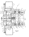
- Mobile frame 3 is connected in known manner (not shown) to fixed frame 2 so as to move back and forth, in relation to the same, to and from a contact position and in the operating direction indicated by arrow 4 in Fig.3.
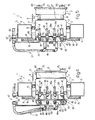
- contact position used in connection with frames 2 and 3 is intended to mean that frames 2 and 3 are arranged contacting each other in the direction of arrow 4, i.e. in the position shown by the continuous line in Fig.s 1, 3 and 4.
- fixed frame 2 is defined by a fixed load-bearing structure 5 extending vertically upwards and comprising two tubular, substantially square-section cross members 6 located over and beneath a central housing 7 connected integral with cross members 6 and supported by the same at a given height over a base (not shown).
- Housing 7 is tubular, is arranged with its axis 8 substantially horizontal and parallel to arrow 4, and comprises a substantially horizontal top wall 9 and bottom wall 10, and two substantially vertical lateral walls 11 facing and adjacent to respective cross members 6.
- Each wall 11 presents an outer rib 12, the lateral surface of which is connected integral with the outer surface of a channel section 13 located between and connected integral with wall 11 and respective cross member 6.
- a metal block 14 integral with both cross member 6 and housing 7, and projecting beyond the edge of cross member 6 for supporting and assembling, on the lateral surface of cross member 6 opposite that facing mobile frame 3, a guide device 15 for a preferably hydraulic bolt 16 described in detail later on.
- mobile frame 3 comprises a central housing 17 closed, on the side opposite that facing fixed frame 2, by a vertical plate 18 and mounted on slideways (not shown) preferably on said base (not shown) so as to move back and forth in said operating direction indicated by arrow 4.
- Housing 17 is tubular, is arranged with its axis coinciding with axis 8, and comprises a substantially horizontal top wall 19 and bottom wall 20 respectively coplanar with walls 9 and 10, and two substantially vertical lateral walls 21 coplanar with respective walls 11.
- housings 7 and 17 present respective flanges 22 and 23 which, when fixed and mobile frames 2 and 3 are arranged in the contacting position shown in Fig.s 1, 3 and 4, are arranged contacting each other via the inter-position of a flexible seal 24.
- machine 1 also comprises a mold 25 in turn comprising a first and second half mold 26 and 27 designed to move in relation to each other to and from a closed position.
- closed position is here and hereinafter used to indicate the mutual arrangement of half molds 26 and 27 shown in the accompanying drawings, i.e. wherein they define a closed molding chamber 28 having a volume corresponding with that of the polystyrene foam product (not shown) being produced.
- mold 25 is designed to produce substantially cylindrical-cup-shaped products (not shown) having a central tubular appendix.
- chamber 28 may obviously be designed differently depending on the products being molded.
- Half mold 26 hereinafter referred to as the "fixed half mold"
- Half mold 26 comprises a first vertical plate 29 perpendicular to axis 8 and having an outer contour substantially identical to the inner contour of housing 7, so as to fit inside housing 7, in the direction of arrow 4, and into the operating position shown in Fig.s 2 and 3, wherein an outer flange 30 on plate 29 rests, via the interposition of a flexible supporting element 31, on edge 32 of housing 7 on the opposite end to the edge defined by flange 22.
- plate 29 is secured to the end of housing 7 opposite the end facing mobile frame 3, by shifting bolts 16 from the withdrawn position (Fig.1) clear of flange 30, to the extracted position (Fig.s 2 and 3) wherein flange 30 is locked axially in relation to housing 7.
- operating position used in connection with fixed half mold 26 applies to half mold 26 mounted on fixed frame 2 with plate 29 locked by bolts 16, i.e. in the position shown in Fig.s 2, 3 and 5.
- Fixed half mold 26 also comprises a second annular plate 33 parallel to plate 29 and having an inner edge 34 engaged in sliding manner, as described later, by a portion of half mold 27 hereinafter referred to as the "mobile half mold.”
- Plate 33 is rendered releasably integral with plate 29 by means of a number of rods 35 parallel to axis 8, and is fitted, on the surface facing plate 29, with a hollow body 36 defining the surface of chamber 28 facing fixed frame 2, and housed inside housing 7 when fixed half mold 26 is locked in the operating position. In this position, plate 33 is also housed inside housing 7, substantially contacting flange 22.
- machine 1 comprises a line 37 supplying granular polystyrene, and a number of lines supplying utility fluids to chamber 28 and comprising, for example, a number of curing steam supply lines 38, a cooling water supply line 38a, and a compressed air supply line 39.
- Lines 37, 38, 38a and 39 comprise respective input portions 40, 41, 41a and 42 connected integral with fixed frame 2, and respective output portions 43, 44, 44a and 45 on fixed half mold 26.
- output portion 43 of line 37 comprises a number of injectors 46 (only two of which are shown) for injecting granular polystyrene directly into chamber 28.
- mobile half mold 27 comprises a plate 52 shaped so as to engage an opening defined by flange 23, and arranged perpendicular to axis 8 and facing plate 33.
- the surface of plate 52 facing plate 33 is fitted integral with a body 53 designed to fit inside body 36 so as to define, with the same, said chamber 28 when half molds 26 and 27 are arranged in said closed position shown in Fig.s 1 to 3.
- Half molds 26 and 27 are locked in releasable manner in said closed position by a lock device 54 which, in the example shown, comprises a rod 55 extending, in rotary and axially-sliding manner and parallel to axis 8, through a hole formed in plate 29.
- Device 54 also comprises a plate 56 integral with shaped body 53 and having a threaded through hole 57 engaged by a threaded end portion of rod 55 against the thrust exerted by a spring 58 compressed between plate 56 and an intermediate flange 59 on rod 55, on the opposite side of shaped body 36 in relation to plate 56.
- Mobile half mold 27 is connectable to mobile frame 3 by means of a coupling device 60 on mobile frame 3.
- Said device 60 comprises a number of pins 61 (only two of which are shown) extending from plate 52 towards plate 18, parallel to axis 8, and each comprising a first and second substantially cylindrical portion 62 and 63.
- Said first portion 62 connected to plate 52 by an axial screw 64, is larger in diameter than said second portion, so as to define an annular connecting shoulder 65 separated from plate 52 by a distance substantially equal to the length of housing 17, so that, when shoulder 65 contacts plate 18 (Fig.3), plate 52 is substantially coplanar with flange 23.
- Portion 63 of each pin 61 engages in sliding manner a respective through hole 66 in plate 18, and presents a first and second annular groove 67 and 68 located a given distance apart, and a tip 69.
- the distance between groove 67 and shoulder 65 is equal to the thickness of plate 18, while groove 68 is located close to tip 69 and may even be dispensed with, as described later on.
- coupling device 60 comprises a releasable clip joint 70 on wall 18, designed to selectively engage grooves 67 and 68 for locking mobile frame 3 in relation to mobile half mold 27 in two axial positions respectively referred to hereinafter as the "work position” and "pull position.”
- machine 1 comprises a number of push elements 71 connected to mobile frame 3 for moving it in the direction of arrow 4, and may optionally comprise further external push elements 72 for moving mold 25 into said operating position in the direction of arrow 4.
- mold 25 is assembled on to machine 1 as follows.
- mold 25, with half molds 26 and 27 maintained in the "closed position” by device 54 is moved, e.g. by means of a carriage (not shown), in the direction of arrow 4 towards fixed frame 2, until half mold 27 is housed completely inside housing 7.
- mobile frame 3 is maintained in the "contact position” by pushers 71.
- Mold 25 is fed forward by said carriage (not shown) until pins 61 on mobile half mold 27 engage respective holes 66 in plate 18, and respective grooves 68 project beyond plate 18.
- clip joints 70 are activated for locking mobile frame 3 in relation to half mold 27 in said "pull position”
- push elements 71 are activated for moving mobile frame 3 away from fixed frame 2 and so moving mold 25 towards fixed frame 2 and into said "operating position” wherein mold 25 is locked by clamping fixed half mold 26 via bolts 16.
- mobile frame 3 thus provides, among other things, for moving mold 25 rapidly and accurately into said "operating position.”
- fast-fit couplings 47, 48, 48a and 49 lock automatically, thus enabling mold 25, in one movement of mobile frame 3, to be assembled rapidly, fully automatically and in fully operative manner on to fixed frame 2.
- joints 70 are released to enable push elements 71 to move mobile frame 3 into said "contact position.”
- portions 63 of pins 61 slide along holes 66 until joints 70 engage grooves 67, thus locking mobile frame 3 on to half mold 27 in said "work position.”
- lock device 54 is eliminated for mutually releasing half molds 26 and 27 and enabling mobile frame 3 to move back and forth in the direction of arrow 4, thus opening and closing mold 25, and enabling granular polystyrene and utility fluids to be fed into molding chamber 28, during the successive intervals in which mold 25 is closed, for producing the required polystyrene foam products.
- the above assembly (or reverse disassembly) and molding procedure may be varied if, instead of connecting mobile frame 3 to mobile half mold 27 and subsequently withdrawing frame 3 from said "contact position", final displacement of mold 25 into said "operating position” is performed directly by push elements 72 connected to mold 25 (and consisting, for example, of a powered carriage).
- grooves 68 are dispensed with, and mobile frame 3 is maintained in a withdrawn position (shown by the dotted line in Fig. 3) clear of pins 61, until mold 25 is locked into the "operative position.” Only at this point is mobile frame 3 moved by push elements 71 into the "contact position” wherein joints 70 are activated for locking mobile frame 3 on to mobile half mold 27 in said "work position.”
Landscapes
- Moulds For Moulding Plastics Or The Like (AREA)
- Manufacture Of Porous Articles, And Recovery And Treatment Of Waste Products (AREA)
- Processing And Handling Of Plastics And Other Materials For Molding In General (AREA)
- Casting Or Compression Moulding Of Plastics Or The Like (AREA)
- Molds, Cores, And Manufacturing Methods Thereof (AREA)
Applications Claiming Priority (2)
| Application Number | Priority Date | Filing Date | Title |
|---|---|---|---|
| IT67428A IT1240949B (it) | 1990-06-12 | 1990-06-12 | Metodo e macchina per la produzione di pezzi di polistirolo espanso. |
| IT6742890 | 1990-06-12 |
Publications (2)
| Publication Number | Publication Date |
|---|---|
| EP0461509A1 true EP0461509A1 (fr) | 1991-12-18 |
| EP0461509B1 EP0461509B1 (fr) | 1996-01-17 |
Family
ID=11302308
Family Applications (1)
| Application Number | Title | Priority Date | Filing Date |
|---|---|---|---|
| EP91109054A Expired - Lifetime EP0461509B1 (fr) | 1990-06-12 | 1991-06-03 | Méthode et appareil pour la fabrication de produits à base de mousse de polystyrène |
Country Status (6)
| Country | Link |
|---|---|
| US (2) | US5238624A (fr) |
| EP (1) | EP0461509B1 (fr) |
| AT (1) | ATE133104T1 (fr) |
| DE (1) | DE69116439T2 (fr) |
| ES (1) | ES2083482T3 (fr) |
| IT (1) | IT1240949B (fr) |
Families Citing this family (8)
| Publication number | Priority date | Publication date | Assignee | Title |
|---|---|---|---|---|
| US5454703A (en) * | 1994-06-30 | 1995-10-03 | Saturn Corporation | Apparatus for molding expanded polymer beads |
| JP3744635B2 (ja) * | 1997-02-17 | 2006-02-15 | アイシン高丘株式会社 | 発泡成形装置 |
| EP1114707A4 (fr) * | 1998-03-31 | 2002-03-20 | Daisen Industry Co Ltd | Machine et procede de moulage interne de mousse a base de resine synthetique |
| WO2010088365A2 (fr) * | 2009-01-29 | 2010-08-05 | Radva Corporation | Machine à mouler à double plateau |
| KR101574690B1 (ko) | 2014-07-11 | 2015-12-04 | (주)엠코리아 | 일방향 조립형 금형장치 |
| CN108312417B (zh) * | 2018-03-19 | 2024-01-19 | 江苏昊晟塑业科技有限公司 | 泡塑机的发泡温度控制装置 |
| CN109016320A (zh) * | 2018-09-08 | 2018-12-18 | 广东奔迪新材料科技有限公司 | 一种热塑性聚合物颗粒模内模塑发泡成型装置及其成型方法 |
| DE102019214066A1 (de) * | 2019-09-16 | 2021-03-18 | Erlenbach Gmbh | Maschinensystem |
Citations (1)
| Publication number | Priority date | Publication date | Assignee | Title |
|---|---|---|---|---|
| EP0190663A2 (fr) * | 1985-02-02 | 1986-08-13 | Hans Erlenbach | Dispositif pour produire des corps moulés à partir de granulés de matière synthétique moussante |
Family Cites Families (25)
| Publication number | Priority date | Publication date | Assignee | Title |
|---|---|---|---|---|
| GB828154A (en) * | 1955-05-05 | 1960-02-17 | Agricola Reg Trust | Method of working expanded synthetic resin materials and articles made by the method |
| US3141192A (en) * | 1961-12-19 | 1964-07-21 | Creative Ideas Inc | Molding apparatus |
| FR1508218A (fr) * | 1966-11-21 | 1968-01-05 | Prod Synthetiques Appliques Pr | Procédé et dispositif pour le remplissage de moules |
| BE790999A (fr) * | 1971-11-29 | 1973-03-01 | Pont A Mousson | Procede et machine perfectionnes pour la fabrication de pieces moulees en matiere plastique expansee |
| US3801244A (en) * | 1972-02-08 | 1974-04-02 | H Eisenberg | Apparatus for making a foamed article having a plastic skin bonded thereto |
| US3837769A (en) * | 1972-07-29 | 1974-09-24 | H Erlenbach | Apparatus for the manufacture of molded articles of foam-forming thermoplastic synthetics |
| FR2295832A1 (fr) * | 1974-12-23 | 1976-07-23 | Creusot Loire | Machine d'injection de matiere plastique |
| DE2613768C3 (de) * | 1976-03-31 | 1984-09-06 | Fa. Ph. Kurtz, 6981 Hasloch | Vorrichtung zum zweistufigen Herstellen von geschäumten Thermoplast-Erzeugnissen |
| US4233006A (en) * | 1978-10-10 | 1980-11-11 | Wheaton Industries | Machine for forming expanded resinous products |
| JPS55128438A (en) * | 1979-03-28 | 1980-10-04 | Badische Yuka Co Ltd | Cooling method and device fit for forming foamed synthetic resin |
| JPS572735A (en) * | 1980-06-06 | 1982-01-08 | Sekisui Plastics Co Ltd | Manufacture of foamed thermoplastic resin molded body |
| US4315727A (en) * | 1980-11-14 | 1982-02-16 | Pemco-Kalamazoo, Inc. | Rotary ball lock |
| WO1983001595A1 (fr) * | 1981-11-02 | 1983-05-11 | Idetsuki, Kiyoto | Procede de production d'un article moule composite |
| DE3237175A1 (de) * | 1981-12-29 | 1984-04-12 | Flewu AG, 9000 St. Gallen | Form zu herstellung von formlingen aus aufgeschaeumtem thermoplastischem kunststoff |
| US4456443A (en) * | 1982-11-26 | 1984-06-26 | Design Engineering Service Inc. | Machine for steam chest molding of foamed material |
| JPS6061215A (ja) * | 1983-09-13 | 1985-04-09 | Sekisui Plastics Co Ltd | 発泡成形における原料の充填方法 |
| US4627946A (en) * | 1983-11-07 | 1986-12-09 | Morval-Durofoam Ltd. | Method and molding apparatus for molding expanded polystyrene articles having smooth surfaces |
| JPS60124239A (ja) * | 1983-12-07 | 1985-07-03 | Sekisui Plastics Co Ltd | 表皮材付発泡成形品の製造方法 |
| DE3603108A1 (de) * | 1986-02-01 | 1987-08-06 | Hans Erlenbach | Vorrichtung zum herstellen von formlingen aus aufgeschaeumtem kunststoff |
| US4818451A (en) * | 1986-04-02 | 1989-04-04 | Mitsubishi Yuka Badische Co., Ltd. | Method of preparing a foamed molded article and blow-filling gun apparatus for use therein |
| JPS6353016A (ja) * | 1986-08-22 | 1988-03-07 | Toyo Mach & Metal Co Ltd | 発泡成形機 |
| US4781555A (en) * | 1987-01-07 | 1988-11-01 | Efp Corp. | Apparatus for forming molded patterns |
| JPS63222831A (ja) * | 1987-03-13 | 1988-09-16 | Fanuc Ltd | 電動式金型クランプ機構 |
| JPH01209127A (ja) * | 1988-02-17 | 1989-08-22 | Kanegafuchi Chem Ind Co Ltd | 熱可塑性樹脂発泡粒子の型内成形法 |
| DE4029431A1 (de) * | 1990-09-17 | 1992-03-26 | Karl Hehl | Kupplungseinrichtung an der spritzgiessform einer kunststoff-spritzgiessmaschine |
-
1990
- 1990-06-12 IT IT67428A patent/IT1240949B/it active IP Right Grant
-
1991
- 1991-06-03 DE DE69116439T patent/DE69116439T2/de not_active Expired - Lifetime
- 1991-06-03 ES ES91109054T patent/ES2083482T3/es not_active Expired - Lifetime
- 1991-06-03 AT AT91109054T patent/ATE133104T1/de not_active IP Right Cessation
- 1991-06-03 EP EP91109054A patent/EP0461509B1/fr not_active Expired - Lifetime
- 1991-06-10 US US07/713,134 patent/US5238624A/en not_active Expired - Lifetime
-
1993
- 1993-05-20 US US08/065,180 patent/US5370515A/en not_active Expired - Lifetime
Patent Citations (1)
| Publication number | Priority date | Publication date | Assignee | Title |
|---|---|---|---|---|
| EP0190663A2 (fr) * | 1985-02-02 | 1986-08-13 | Hans Erlenbach | Dispositif pour produire des corps moulés à partir de granulés de matière synthétique moussante |
Non-Patent Citations (2)
| Title |
|---|
| KUNSTSTOFFE, vol. 78, no. 10, October 1988, pages 984-990, Munich, DE; R.K. HASLOCH: "EPS-Formteil- und Blockverarbeitung" * |
| MODERN PLASTICS INTERNATIONAL, vol. 18, no. 10, October 1988, pages 42-45, Lausanne, CH; P. MAPLESTON: "New technologies broaden scope for bead molding equipment" * |
Also Published As
| Publication number | Publication date |
|---|---|
| DE69116439T2 (de) | 1996-07-04 |
| EP0461509B1 (fr) | 1996-01-17 |
| ATE133104T1 (de) | 1996-02-15 |
| IT9067428A0 (it) | 1990-06-12 |
| IT9067428A1 (it) | 1991-12-12 |
| DE69116439D1 (de) | 1996-02-29 |
| US5238624A (en) | 1993-08-24 |
| US5370515A (en) | 1994-12-06 |
| ES2083482T3 (es) | 1996-04-16 |
| IT1240949B (it) | 1993-12-27 |
Similar Documents
| Publication | Publication Date | Title |
|---|---|---|
| US7829007B2 (en) | Injection-moulding system | |
| EP0461509B1 (fr) | Méthode et appareil pour la fabrication de produits à base de mousse de polystyrène | |
| CN102371648A (zh) | 用于注射模塑的快速更换模塑系统 | |
| EP2066482A2 (fr) | Procédé et machine de moulage de caoutchouc à cavitation élevée et tonnage faible | |
| US5238387A (en) | Apparatus for molding a product of synthetic resin | |
| US5044919A (en) | Synthetic resin molding apparatus | |
| US3504403A (en) | Differential pressure plastic forming machine partible mold mechanism for forming articles in a plastic sheet | |
| GB2227445A (en) | Synthetic resin molding apparatus | |
| CN213500579U (zh) | 一体式吊环瓶胚成型模具 | |
| CN220242239U (zh) | 一种擦窗机壳体的成型模具 | |
| KR0158710B1 (ko) | 플라스틱 성형 금형장치내의 가동부재 구동장치 | |
| CN220614673U (zh) | 一种便于更换模仁的模具 | |
| CN222768878U (zh) | 一种可更换型芯的管件配件模具 | |
| CN222610408U (zh) | 一种注吹塑一体模具 | |
| CN223821012U (zh) | 大尺寸户外塑料沙滩躺椅气辅成型模具 | |
| CN220052783U (zh) | 一种模具快拆装置 | |
| CN118322497B (zh) | 一种管型塑胶制品脱模装置 | |
| CN219988208U (zh) | 一种具有双重限位结构的精密塑胶模具 | |
| CN121848607A (zh) | 一种pp检查井多规格产品共模模具 | |
| KR100669173B1 (ko) | 사출성형기 | |
| CN213440914U (zh) | 一种滑块机构及模具 | |
| JPH04323014A (ja) | 立て形射出成形機 | |
| KR100391574B1 (ko) | 사출성형용 금형장치 및 이를 이용한 사출성형방법 | |
| EP0658137A4 (fr) | Moule a serrage rapide pour appareil de moulage. | |
| CN120134524A (zh) | 一种能便捷换模的泡沫成型机 |
Legal Events
| Date | Code | Title | Description |
|---|---|---|---|
| PUAI | Public reference made under article 153(3) epc to a published international application that has entered the european phase |
Free format text: ORIGINAL CODE: 0009012 |
|
| AK | Designated contracting states |
Kind code of ref document: A1 Designated state(s): AT CH DE ES FR GB IT LI SE |
|
| 17P | Request for examination filed |
Effective date: 19920616 |
|
| 17Q | First examination report despatched |
Effective date: 19930831 |
|
| GRAA | (expected) grant |
Free format text: ORIGINAL CODE: 0009210 |
|
| AK | Designated contracting states |
Kind code of ref document: B1 Designated state(s): AT CH DE ES FR GB IT LI SE |
|
| REF | Corresponds to: |
Ref document number: 133104 Country of ref document: AT Date of ref document: 19960215 Kind code of ref document: T |
|
| RIN1 | Information on inventor provided before grant (corrected) |
Inventor name: BAZZICA, CARLO |
|
| REF | Corresponds to: |
Ref document number: 69116439 Country of ref document: DE Date of ref document: 19960229 |
|
| REG | Reference to a national code |
Ref country code: CH Ref legal event code: NV Representative=s name: NOVAPAT - CABINET CHEREAU S.A. |
|
| ITF | It: translation for a ep patent filed | ||
| ET | Fr: translation filed | ||
| REG | Reference to a national code |
Ref country code: ES Ref legal event code: FG2A Ref document number: 2083482 Country of ref document: ES Kind code of ref document: T3 |
|
| PLBE | No opposition filed within time limit |
Free format text: ORIGINAL CODE: 0009261 |
|
| STAA | Information on the status of an ep patent application or granted ep patent |
Free format text: STATUS: NO OPPOSITION FILED WITHIN TIME LIMIT |
|
| 26N | No opposition filed | ||
| REG | Reference to a national code |
Ref country code: GB Ref legal event code: IF02 |
|
| PGFP | Annual fee paid to national office [announced via postgrant information from national office to epo] |
Ref country code: ES Payment date: 20100517 Year of fee payment: 20 Ref country code: FR Payment date: 20100526 Year of fee payment: 20 |
|
| PGFP | Annual fee paid to national office [announced via postgrant information from national office to epo] |
Ref country code: IT Payment date: 20100621 Year of fee payment: 20 Ref country code: AT Payment date: 20100624 Year of fee payment: 20 |
|
| PGFP | Annual fee paid to national office [announced via postgrant information from national office to epo] |
Ref country code: CH Payment date: 20100526 Year of fee payment: 20 |
|
| PGFP | Annual fee paid to national office [announced via postgrant information from national office to epo] |
Ref country code: DE Payment date: 20100819 Year of fee payment: 20 Ref country code: GB Payment date: 20100507 Year of fee payment: 20 Ref country code: SE Payment date: 20100609 Year of fee payment: 20 |
|
| REG | Reference to a national code |
Ref country code: DE Ref legal event code: R071 Ref document number: 69116439 Country of ref document: DE |
|
| REG | Reference to a national code |
Ref country code: DE Ref legal event code: R071 Ref document number: 69116439 Country of ref document: DE |
|
| REG | Reference to a national code |
Ref country code: CH Ref legal event code: PL |
|
| REG | Reference to a national code |
Ref country code: GB Ref legal event code: PE20 Expiry date: 20110602 |
|
| PG25 | Lapsed in a contracting state [announced via postgrant information from national office to epo] |
Ref country code: GB Free format text: LAPSE BECAUSE OF EXPIRATION OF PROTECTION Effective date: 20110602 |
|
| REG | Reference to a national code |
Ref country code: SE Ref legal event code: EUG |
|
| REG | Reference to a national code |
Ref country code: ES Ref legal event code: FD2A Effective date: 20120424 |
|
| PG25 | Lapsed in a contracting state [announced via postgrant information from national office to epo] |
Ref country code: ES Free format text: LAPSE BECAUSE OF EXPIRATION OF PROTECTION Effective date: 20110604 |
|
| PG25 | Lapsed in a contracting state [announced via postgrant information from national office to epo] |
Ref country code: DE Free format text: LAPSE BECAUSE OF EXPIRATION OF PROTECTION Effective date: 20110604 |