EP0461575B1 - Mobiles Abbrennstumpf-Schweissaggregat - Google Patents
Mobiles Abbrennstumpf-Schweissaggregat Download PDFInfo
- Publication number
- EP0461575B1 EP0461575B1 EP91109460A EP91109460A EP0461575B1 EP 0461575 B1 EP0461575 B1 EP 0461575B1 EP 91109460 A EP91109460 A EP 91109460A EP 91109460 A EP91109460 A EP 91109460A EP 0461575 B1 EP0461575 B1 EP 0461575B1
- Authority
- EP
- European Patent Office
- Prior art keywords
- block assembly
- cylinders
- clamping
- longitudinal direction
- upsetting
- Prior art date
- Legal status (The legal status is an assumption and is not a legal conclusion. Google has not performed a legal analysis and makes no representation as to the accuracy of the status listed.)
- Expired - Lifetime
Links
Images

Classifications
-
- B—PERFORMING OPERATIONS; TRANSPORTING
- B23—MACHINE TOOLS; METAL-WORKING NOT OTHERWISE PROVIDED FOR
- B23K—SOLDERING OR UNSOLDERING; WELDING; CLADDING OR PLATING BY SOLDERING OR WELDING; CUTTING BY APPLYING HEAT LOCALLY, e.g. FLAME CUTTING; WORKING BY LASER BEAM
- B23K11/00—Resistance welding; Severing by resistance heating
- B23K11/002—Resistance welding; Severing by resistance heating specially adapted for particular articles or work
- B23K11/0073—Butt welding of long articles advanced axially
-
- E—FIXED CONSTRUCTIONS
- E01—CONSTRUCTION OF ROADS, RAILWAYS, OR BRIDGES
- E01B—PERMANENT WAY; PERMANENT-WAY TOOLS; MACHINES FOR MAKING RAILWAYS OF ALL KINDS
- E01B29/00—Laying, rebuilding, or taking-up tracks; Tools or machines therefor
- E01B29/42—Undetachably joining or fastening track components in or on the track, e.g. by welding, by gluing; Pre-assembling track components by gluing; Sealing joints with filling components
- E01B29/46—Devices for holding, positioning, or urging together the rail ends
Definitions
- the invention relates to a mobile flash butt welding unit according to the preamble of claim 1.
- EP-A 0 326 793 discloses a mobile flash-butt welding unit of this type, which is fastened in a height-adjustable manner on a machine that can be moved in the same way.
- Each of the two unit blocks which can be displaced relative to one another via upsetting cylinders in the longitudinal direction of the rail or machine, has a pair of clamping and welding jaws, which can be pressed onto the rail web by a hydraulic clamping cylinder.
- the pairs of clamping jaws and welding jaws also serve as electrodes for the clamping function, through which the welding current can be transferred to the two rail end regions to be welded together.
- the clamped rail ends are moved together with the two unit blocks at approx.
- the opposite ends of the clamping tongs in the longitudinal direction of the rails are each connected to one another by a hydraulic cylinder.
- the above-mentioned upsetting stroke is carried out using the upsetting cylinders of the welding unit and the two hydraulic cylinders of the rail pulling device.
- a mobile flash butt welding unit for welding the two ends of rails adjacent to one another on the end faces.
- This unit consists of a support that is flexible in the vertical and horizontal directions and is placed in the middle of a vehicle on the two rail ends to be welded.
- six clamping devices are arranged, the jaws of which are adapted to the shape of the rail profile.
- the clamping devices on the fixed rail end are rigidly mounted on the flexible support, while the clamping devices on the longitudinally movable rail end are mounted on the support so as to be longitudinally movable. They are connected to two hydraulic cylinders via articulated push and pull rods.
- the support is designed in the area of the weld so that it is accessible.
- a flash butt welding unit which is used for welding installed rails.
- Such a welding unit is composed of two unit blocks which can be displaced relative to one another in the longitudinal direction of the rails or of two upsetting cylinders and which are each formed from two parts which can be pivoted relative to one another about an axis running in the longitudinal direction of the upsetting cylinders. These parts have clamping jaws that act as electrodes in their lower area for simultaneous contact on both sides of the rail and are connected to one another in their upper end areas by a pressure cylinder.
- the object of the present invention is to provide a mobile flash butt welding unit of the generic type, with which particularly high tensile forces can be applied to the rail ends to be connected with only a slight change in the design of the two unit blocks.
- This object is achieved by the features in claim 1.
- This solution according to the invention creates a structural unit enables, with largely structural retention of the flash butt welding unit, which has already been tried and tested, and avoiding overloading the clamping jaws or the block parts connected to them, significantly higher tensile forces can be applied to the rail ends to be welded.
- the mechanical connection of the clamping elements to the two aggregate blocks ensures simple, synchronous transmission of the tensile forces both through the clamping jaws of the aggregate blocks, which act as electrodes, and through the external clamping elements, without the use of an expensive and complicated synchronous control. This means that the articulation of the clamping elements automatically moves them along with the longitudinal displacement of the clamping jaws or the unit blocks.
- Another advantage of the arrangement outside the two unit blocks can also be seen in the fact that the clamping elements can be dimensioned accordingly generously, regardless of the structural design of the unit blocks. Thus, particularly heavy or long rails can be welded without any problems with such a welding unit.
- the embodiment of the invention characterized by the features in claim 2 is characterized by a structurally particularly simple solution which is particularly effective in connection with the lever action of the clamping pliers.
- the function of the two unit blocks for performing the welding work is in no way impaired.
- the design of the welding unit according to claim 3 enables a substantial increase in the tensile forces that can be applied, the arrangement in a common plane bringing the longitudinal axes of the upsetting cylinders to lie in close proximity to the horizontal plane of symmetry of the clamping jaws. This ensures that the tensile forces are avoided while avoiding disadvantageous leverage acting around an axis running in the transverse direction of the rail are transferable to the jaws.
- the embodiment of the invention according to claim 4 allows precise control of the opening and closing movements of the clamping tongs, the tension members connecting the clamping tongs to the unit blocks being designed in a simple manner for the problem-free transmission of the highest tensile forces while avoiding a change in length.
- the arrangement of the clamping tongs and tension members in a common plane of symmetry with respect to the height of the clamping jaws has the advantage that the high tensile forces can be transferred to the rail ends while avoiding a tilting moment effective on the pivot axis of the clamping tongs. This means that a very disadvantageous bending load on both the clamping jaw swivel axes and the rail ends is reliably excluded.
- the design of the unit according to the features of claim 8 allows an unimpeded longitudinal displacement of the weld bead shearing device with unchanged spacing of the two unit blocks from each other. This makes it easy to remove the Welding bead can be carried out by the upsetting cylinder while maintaining the tensile forces acting on the welded rail ends, so that the tensile stresses only become effective after the welded joint has cooled.
- a further embodiment of the invention is characterized in that the pressing forces on the rail can be set with the aid of the pressing cylinder independently of the tensile forces running in the longitudinal direction of the rail with such pliers body.
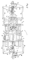
- a flash butt welding unit 1 shown in FIGS. 1 and 2 is composed essentially of two unit blocks 2 spaced apart from one another, which are connected to one another in their longitudinal direction by four compression cylinders 3 arranged in a common horizontal plane and running parallel to one another.
- Each of the two aggregate blocks 2 each consists of two aggregate parts 4, 5, which can be pivoted relative to one another about an axis running in the longitudinal direction of the rail, with clamping jaws 6 acting as electrodes for contacting two rails or rail ends 7 to be welded to one another.
- the two aggregate parts 4, 5 are connected to one another in their upper end region by means of a lever system 8 and a vertical clamping cylinder connected thereto for pressing the clamping jaws 6 onto the rails 7.
- An aggregate block 2 is connected to a weld bead shearing device 10 which can be displaced in the longitudinal direction of the upsetting cylinders 3 by two shear cylinders 9, pressure cylinders 11 fastened thereon being articulatedly attached to a housing 12 of the aggregate block 2.
- Each unit block 2 is connected in the end region facing away from one another with clamping elements 13 which are spaced apart in the longitudinal direction of the upsetting cylinders 3 and are provided for pressing against the rail on both sides.
- clamping pliers 16 which can be pivoted about a vertical pivot axis 14 and are connected in pairs by a transverse yoke 15.
- These lever-shaped clamping pliers 16 lie opposite one another in the direction perpendicular to the longitudinal direction of the upsetting cylinder 3 or to the longitudinal direction of the rail and are each connected in the region of their short lever arm to a clamping jaw 17 provided for bearing against the rail web.
- the longer lever arms are each with an Housing 12 of the subsequent unit block 2 movably fastened tension member 18 articulated.
- Each of the two transverse yokes 15 is connected to the adjacent aggregate part 4 or 5 by a central spreading cylinder 19 running in the longitudinal direction of the upsetting cylinder 3.
- a common plane of symmetry 20 running perpendicular to the pivot axes 14 of the clamping tongs 16 for the clamping tongs 16 and the tension members 18 connected to an aggregate block 2 is arranged approximately centrally with respect to the height of the clamping jaws 17 or the rail height .
- the secondary circuit of a power plant is integrated in a known manner in order to transform the welding current to low voltage and the required high current. Since the transformation of the current and the workflow itself cause high temperatures, the welding unit 1 is cooled.
- a comprehensive cooling system, not shown, is installed.
- the welding unit 1 is suspended from a double-armed telescopic crane attached to a welding machine.
- the energy supply is provided by a generator arranged in the welding machine and a hydraulic pump.
- a control panel 21 is provided to initiate the various operations.
- the flash butt welding unit 1 is centered with the help of the telescopic crane of the welding machine mentioned above the rail ends 7 to be welded, the two clamping tongs 16 being in the open position by acting on the two expansion cylinders 19 and the clamping jaws 6 of the unit parts 4, 5 (see below Half in Fig.2).
- the two expansion cylinders 19 are acted upon in opposite directions, whereby the jaws 17 come to rest on the rail web.
- the clamping jaws 6 of the unit parts 4 and 5 which simultaneously act as electrodes, are pressed onto the rail web. This clamping of the two rail ends 7 results in their exact height and directional centering.
- the four upsetting cylinders 3 are subjected to increased pressure to initiate the so-called upsetting stroke.
- a welded joint is formed when the rail ends heated to the melting temperature are pressed together. Since the application of these very high compressive impact forces takes place by means of a system of clamping jaws 6 of the unit blocks 2 forming a common structural unit and the clamping pliers 16 connected to them, their synchronous use is ensured while avoiding a complex control device.
- the impact forces are up to one Appropriate resilience of the welded joint after appropriate cooling is exerted on the rails, while acting on the two shear cylinders 9 results in a longitudinal displacement of the weld bead shearing device 10 to remove the weld bead.
- the upsetting cylinders 3 are controlled without pressure and, after the clamping, pressing and spreading cylinders 11, 19 connected to the unit parts 4, 5 and the resulting opening of the clamping jaws 6 and 17, the two unit blocks 2 are longitudinally displaced the arrow direction shown in Figure 1 in the starting position.
- 3 and 4 are formed as pliers-shaped pliers parts 25, 26 which can be pivoted relative to one another about an axis 23 running in the longitudinal direction of the upsetting cylinders 3 and can be placed on the two long sides of a rail 24. These are connected to one another in their upper end regions by connecting members 27 and can be pivoted with the aid of a vertical tensioning cylinder 28 from a clamping position shown in full lines into an opening position shown in dash-dotted lines (FIG. 4). The two pliers parts 25 and 26 are articulated in their lower end area by tension members 29 to the adjacent unit block 2.
- connection of the tension members 29 with the pliers parts 25, 26 is designed in such a way that a slight rotation of the tension members 29 about an axis running in the longitudinal direction thereof is also possible for carrying out the opening movement.
- the lower end regions of the pliers parts 25, 26 have clamping jaws 30 provided for abutment against the rail web.
- the clamping jaws 30 of the clamping elements 22 are pressed against the rail web by the clamping cylinders 28 being pressurized to carry out the closing movement.
- the two rail ends are then welded to one another while acting on the upsetting cylinder 3 in the manner already described.
Landscapes
- Engineering & Computer Science (AREA)
- Mechanical Engineering (AREA)
- Architecture (AREA)
- Civil Engineering (AREA)
- Structural Engineering (AREA)
- Machines For Laying And Maintaining Railways (AREA)
- Butt Welding And Welding Of Specific Article (AREA)
- Resistance Welding (AREA)
- Pressure Welding/Diffusion-Bonding (AREA)
Applications Claiming Priority (2)
| Application Number | Priority Date | Filing Date | Title |
|---|---|---|---|
| AT0129590A AT394960B (de) | 1990-06-15 | 1990-06-15 | Mobiles abbrennstumpf-schweissaggregat |
| AT1295/90 | 1990-06-15 |
Publications (3)
| Publication Number | Publication Date |
|---|---|
| EP0461575A2 EP0461575A2 (de) | 1991-12-18 |
| EP0461575A3 EP0461575A3 (en) | 1992-04-08 |
| EP0461575B1 true EP0461575B1 (de) | 1994-05-25 |
Family
ID=3510797
Family Applications (1)
| Application Number | Title | Priority Date | Filing Date |
|---|---|---|---|
| EP91109460A Expired - Lifetime EP0461575B1 (de) | 1990-06-15 | 1991-06-10 | Mobiles Abbrennstumpf-Schweissaggregat |
Country Status (8)
| Country | Link |
|---|---|
| US (1) | US5099097A (cs) |
| EP (1) | EP0461575B1 (cs) |
| AT (1) | AT394960B (cs) |
| AU (1) | AU636761B2 (cs) |
| CA (1) | CA2043849A1 (cs) |
| CS (1) | CS277167B6 (cs) |
| DE (1) | DE59101701D1 (cs) |
| RU (1) | RU2051016C1 (cs) |
Cited By (1)
| Publication number | Priority date | Publication date | Assignee | Title |
|---|---|---|---|---|
| EA008843B1 (ru) * | 2005-06-24 | 2007-08-31 | Франц Плассер Банбаумашинен-Индустригезельшафт М.Б.Х. | Сварочная машина для сварки рельсов пути |
Families Citing this family (22)
| Publication number | Priority date | Publication date | Assignee | Title |
|---|---|---|---|---|
| ATE145574T1 (de) * | 1992-11-09 | 1996-12-15 | Schlatter Ag | Abbrennstumpfschweissanlage |
| JP2891608B2 (ja) * | 1993-06-04 | 1999-05-17 | 日本鋼管株式会社 | レ−ルクランプ装置及びレ−ルのフラッシュ溶接装置 |
| SE9504368D0 (sv) * | 1995-12-05 | 1995-12-05 | Esab Ab | Hopsvetsningsanordning |
| DE69605551T2 (de) * | 1996-10-11 | 2000-07-13 | Scheuchzer S.A., Lausanne | Verfahren zum Schweissen mindestens eines Schienenstranges und Maschine zur Anwendung dieses Verfahrens |
| RU2186664C2 (ru) * | 1998-01-27 | 2002-08-10 | Институт Электросварки Им. Е.О. Патона Нан Украины | Машина для контактной стыковой сварки рельсов |
| UA55539C2 (uk) * | 2000-11-30 | 2003-04-15 | Інженерний Центр Зварювання Тиском Науково-Технічного Комплексу "Інститут Електрозварювання Ім. Є. О. Патона" Нан України | Машина для контактного стикового зварювання рейок |
| AT5203U3 (de) * | 2002-01-28 | 2003-01-27 | Plasser Bahnbaumasch Franz | Schweissaggregat |
| AT6690U3 (de) * | 2003-11-06 | 2004-11-25 | Plasser Bahnbaumasch Franz | Verfahren zum verschweissen von schienen eines gleises |
| RU2277462C1 (ru) * | 2004-12-10 | 2006-06-10 | Даниил Иванович Беляев | Машина для контактной стыковой сварки оплавлением |
| CN100450693C (zh) * | 2005-05-16 | 2009-01-14 | 中铁一局集团有限公司 | 用移动闪光对焊机进行铁路无缝线路合龙锁定焊接的方法 |
| ES2300936T3 (es) * | 2005-05-18 | 2008-06-16 | Franz Plasser Bahnbaumaschinen-Industriegesellschaft M.B.H. | Maquina soldadora y procedimiento para soldar carriles de una via. |
| CN101024264B (zh) * | 2006-02-17 | 2010-05-12 | 襄樊金鹰轨道车辆有限责任公司 | 铁路移动式焊轨车 |
| RU2321478C1 (ru) * | 2006-06-20 | 2008-04-10 | Закрытое акционерное общество "Псковэлектросвар" | Машина подвесная для стыковой сварки рельсов |
| AT505814B1 (de) * | 2007-09-20 | 2009-06-15 | Plasser Bahnbaumasch Franz | Schweissaggregat zum verschweissen zweier schienen eines gleises |
| RU2372177C2 (ru) * | 2007-12-13 | 2009-11-10 | Владимир Иванович Дедюх | Машина для контактной стыковой сварки рельсов оплавлением |
| RU2369471C1 (ru) * | 2008-06-10 | 2009-10-10 | Открытое акционерное общество Акционерная холдинговая компания "Всероссийский научно-исследовательский и проектно-конструкторский институт металлургического машиностроения имени академика Целикова" (ОАО АХК "ВНИИМЕТМАШ") | Машина для стыковой сварки полос оплавлением |
| US8658935B2 (en) * | 2008-12-24 | 2014-02-25 | Chemetron-Railway Products, Inc. | Welding process with jerk compensation |
| UA121551C2 (en) * | 2014-10-01 | 2020-06-25 | Plasser & Theurer Export Von Bahnbaumaschinen Gmbh | Welding unit |
| DE102016002692A1 (de) | 2016-03-08 | 2017-09-14 | Goldschmidt Thermit Gmbh | Verfahren zur Ermittlung der Neutraltemperatur in langgestreckten Werkstücken |
| AT15368U1 (de) * | 2016-04-01 | 2017-07-15 | Plasser & Theurer Export Von Bahnbaumaschinen Gmbh | Schweißaggregat zum Verschweißen zweier Schienen eines Gleises |
| AT522860B1 (de) * | 2019-07-31 | 2023-05-15 | Plasser & Theurer Export Von Bahnbaumaschinen Gmbh | Schweißaggregat zum Verschweißen von Schienen eines Gleises |
| CN111331234B (zh) * | 2020-04-16 | 2023-06-23 | 哈尔滨工业大学(威海) | 一种闪光对焊自动化焊接夹具及方法 |
Family Cites Families (6)
| Publication number | Priority date | Publication date | Assignee | Title |
|---|---|---|---|---|
| AT357594B (de) * | 1977-12-28 | 1980-07-25 | Plasser Bahnbaumasch Franz | Fahrbare abbrenn-stumpf-schienenschweiss- maschine mit schweisswulst-abtragvorrichtung |
| CH632948A5 (de) * | 1978-11-10 | 1982-11-15 | Schlatter Ag | Einrichtung zum stirnseitigen aneinanderschweissen zweier profilstangen. |
| US4414454A (en) * | 1981-08-13 | 1983-11-08 | H. A. Schlatter Ag | Method of welding continuous rails and apparatus therefor |
| DD244998A1 (de) * | 1985-12-18 | 1987-04-22 | Verkehrswesen Hochschule | Vorrichtung zum ausrichten der schienenenden fuer schienenverbindungsschweissungen |
| ATE74635T1 (de) * | 1988-02-01 | 1992-04-15 | Plasser Bahnbaumasch Franz | Elektrische abbrennstumpf-schweissmaschine zum verschweissen der beiden aneinanderstossenden enden, insbesondere im stossbereich eines schienenstranges eines verlegten gleises. |
| US4929816A (en) * | 1988-02-01 | 1990-05-29 | Franz Plasser Bahnbaumaschinen-Industriegesellschaft Gmbh | Electric flash-butt welding machine and method of providing a welded joint between adjacent ends of rail sections |
-
1990
- 1990-06-15 AT AT0129590A patent/AT394960B/de not_active IP Right Cessation
-
1991
- 1991-04-18 RU SU914895078A patent/RU2051016C1/ru active
- 1991-04-25 CS CS911186A patent/CS277167B6/cs not_active IP Right Cessation
- 1991-05-31 US US07/708,672 patent/US5099097A/en not_active Expired - Lifetime
- 1991-06-04 CA CA002043849A patent/CA2043849A1/en not_active Abandoned
- 1991-06-05 AU AU78160/91A patent/AU636761B2/en not_active Ceased
- 1991-06-10 EP EP91109460A patent/EP0461575B1/de not_active Expired - Lifetime
- 1991-06-10 DE DE59101701T patent/DE59101701D1/de not_active Expired - Fee Related
Cited By (1)
| Publication number | Priority date | Publication date | Assignee | Title |
|---|---|---|---|---|
| EA008843B1 (ru) * | 2005-06-24 | 2007-08-31 | Франц Плассер Банбаумашинен-Индустригезельшафт М.Б.Х. | Сварочная машина для сварки рельсов пути |
Also Published As
| Publication number | Publication date |
|---|---|
| EP0461575A2 (de) | 1991-12-18 |
| CA2043849A1 (en) | 1991-12-16 |
| DE59101701D1 (de) | 1994-06-30 |
| US5099097A (en) | 1992-03-24 |
| ATA129590A (de) | 1992-01-15 |
| RU2051016C1 (ru) | 1995-12-27 |
| AU7816091A (en) | 1991-12-19 |
| EP0461575A3 (en) | 1992-04-08 |
| AU636761B2 (en) | 1993-05-06 |
| AT394960B (de) | 1992-08-10 |
| CS277167B6 (en) | 1992-11-18 |
Similar Documents
| Publication | Publication Date | Title |
|---|---|---|
| AT394960B (de) | Mobiles abbrennstumpf-schweissaggregat | |
| EP0597215B1 (de) | Abbrennstumpfschweissanlage | |
| EP2315877B1 (de) | Schweissaggregat zum verschweissen von schienen eines gleises | |
| EP2373845B1 (de) | Schweissaggregat zum verschweissen von schienen | |
| AT402830B (de) | Schienenziehvorrichtung zum längsverschieben von schienen verlegter gleise | |
| DE4020804A1 (de) | Vorrichtung und verfahren zum anschweissen von verbindungsbauteilen an ein rohr | |
| DE3726587A1 (de) | Verfahren und vorrichtung zum induktionserhitzen und druckschweissen von zwei schweissbaren oberflaechen zweier bauteile | |
| CH682681A5 (de) | Zieh-Vorrichtung zum Längsverschieben von Schienen. | |
| DE2918388A1 (de) | Einrichtung zum stirnseitigen aneinanderschweissen zweier profilstangen | |
| DE102012220273A1 (de) | Kettenbiegemaschine | |
| DE69630049T2 (de) | Schweissvorrichtung | |
| EP3201395B1 (de) | Schweissaggregat | |
| DE19807457A1 (de) | Verfahren und Vorrichtung zum Reibschweißen von Eisenbahnschienen | |
| EP0326793B1 (de) | Elektrische Abbrennstumpf-Schweissmaschine zum Verschweissen der beiden aneinanderstossenden Enden, insbesondere im Stossbereich eines Schienenstranges eines verlegten Gleises | |
| DE3221834C2 (de) | Schienenzange | |
| WO2016193392A1 (de) | Schienenzange mit vertikaler führung | |
| DE102015222704A1 (de) | Schweißwerkzeug und Verfahren zum Widerstandspunktschweißen | |
| EP4004287B1 (de) | Schweissaggregat zum verschweissen von schienen eines gleises | |
| DE2733252B2 (de) | Verfahren und Vorrichtung zum Herstellen eines Gitterträgers | |
| DE2410726C3 (de) | Elektrische Widerstandsschweißmaschine | |
| EP3126087A1 (de) | SCHWEIßELEKTRODENEINHEIT | |
| DE19804725A1 (de) | Nietmaschine | |
| WO2026008185A1 (de) | Schmiedepresse, schmiedevorrichtung und verfahren zum schmieden | |
| CH680913A5 (cs) | ||
| DE3744933C2 (de) | Vorrichtung zum Induktionserhitzen und Druckverschweißen zweier Werkstücke |
Legal Events
| Date | Code | Title | Description |
|---|---|---|---|
| PUAI | Public reference made under article 153(3) epc to a published international application that has entered the european phase |
Free format text: ORIGINAL CODE: 0009012 |
|
| AK | Designated contracting states |
Kind code of ref document: A2 Designated state(s): DE FR GB IT |
|
| PUAL | Search report despatched |
Free format text: ORIGINAL CODE: 0009013 |
|
| AK | Designated contracting states |
Kind code of ref document: A3 Designated state(s): DE FR GB IT |
|
| 17P | Request for examination filed |
Effective date: 19920803 |
|
| 17Q | First examination report despatched |
Effective date: 19930212 |
|
| GRAA | (expected) grant |
Free format text: ORIGINAL CODE: 0009210 |
|
| AK | Designated contracting states |
Kind code of ref document: B1 Designated state(s): DE FR GB IT |
|
| ITF | It: translation for a ep patent filed | ||
| REF | Corresponds to: |
Ref document number: 59101701 Country of ref document: DE Date of ref document: 19940630 |
|
| GBT | Gb: translation of ep patent filed (gb section 77(6)(a)/1977) |
Effective date: 19940607 |
|
| ET | Fr: translation filed | ||
| PLBE | No opposition filed within time limit |
Free format text: ORIGINAL CODE: 0009261 |
|
| STAA | Information on the status of an ep patent application or granted ep patent |
Free format text: STATUS: NO OPPOSITION FILED WITHIN TIME LIMIT |
|
| 26N | No opposition filed | ||
| REG | Reference to a national code |
Ref country code: GB Ref legal event code: IF02 |
|
| PGFP | Annual fee paid to national office [announced via postgrant information from national office to epo] |
Ref country code: DE Payment date: 20080812 Year of fee payment: 18 |
|
| PGFP | Annual fee paid to national office [announced via postgrant information from national office to epo] |
Ref country code: FR Payment date: 20090526 Year of fee payment: 19 Ref country code: IT Payment date: 20080627 Year of fee payment: 18 |
|
| PGFP | Annual fee paid to national office [announced via postgrant information from national office to epo] |
Ref country code: GB Payment date: 20090428 Year of fee payment: 19 |
|
| PG25 | Lapsed in a contracting state [announced via postgrant information from national office to epo] |
Ref country code: DE Free format text: LAPSE BECAUSE OF NON-PAYMENT OF DUE FEES Effective date: 20100101 |
|
| GBPC | Gb: european patent ceased through non-payment of renewal fee |
Effective date: 20100610 |
|
| REG | Reference to a national code |
Ref country code: FR Ref legal event code: ST Effective date: 20110228 |
|
| PG25 | Lapsed in a contracting state [announced via postgrant information from national office to epo] |
Ref country code: IT Free format text: LAPSE BECAUSE OF NON-PAYMENT OF DUE FEES Effective date: 20090610 |
|
| PG25 | Lapsed in a contracting state [announced via postgrant information from national office to epo] |
Ref country code: FR Free format text: LAPSE BECAUSE OF NON-PAYMENT OF DUE FEES Effective date: 20100630 |
|
| PG25 | Lapsed in a contracting state [announced via postgrant information from national office to epo] |
Ref country code: GB Free format text: LAPSE BECAUSE OF NON-PAYMENT OF DUE FEES Effective date: 20100610 |