EP0462313A2 - Table à pieds pliants - Google Patents
Table à pieds pliants Download PDFInfo
- Publication number
- EP0462313A2 EP0462313A2 EP90119970A EP90119970A EP0462313A2 EP 0462313 A2 EP0462313 A2 EP 0462313A2 EP 90119970 A EP90119970 A EP 90119970A EP 90119970 A EP90119970 A EP 90119970A EP 0462313 A2 EP0462313 A2 EP 0462313A2
- Authority
- EP
- European Patent Office
- Prior art keywords
- gas spring
- legs
- underside
- table according
- leg
- Prior art date
- Legal status (The legal status is an assumption and is not a legal conclusion. Google has not performed a legal analysis and makes no representation as to the accuracy of the status listed.)
- Withdrawn
Links
Images

Classifications
-
- A—HUMAN NECESSITIES
- A47—FURNITURE; DOMESTIC ARTICLES OR APPLIANCES; COFFEE MILLS; SPICE MILLS; SUCTION CLEANERS IN GENERAL
- A47B—TABLES; DESKS; OFFICE FURNITURE; CABINETS; DRAWERS; GENERAL DETAILS OF FURNITURE
- A47B3/00—Folding or stowable tables
- A47B3/08—Folding or stowable tables with legs pivoted to top or underframe
- A47B3/091—Folding or stowable tables with legs pivoted to top or underframe with struts supporting the legs
- A47B3/0911—Folding or stowable tables with legs pivoted to top or underframe with struts supporting the legs the struts being permanently connected to top and leg or underframe and leg
- A47B3/0913—Folding or stowable tables with legs pivoted to top or underframe with struts supporting the legs the struts being permanently connected to top and leg or underframe and leg the strut being of two parts slidable relative to one another, e.g. telescopic struts
Definitions
- the invention relates to a table with foldable table legs against the underside of the table top.
- support brackets are articulated on the foldable table legs, which are mounted in a guide rail arranged on the underside of the table top, which have recesses for locking these support brackets in the two end positions of the foldable table legs.
- metallic parts slide on one another without lubrication and correspondingly loud and that the support bracket must always be unlocked by hand before the table legs are pivoted.
- the invention has for its object to design a table of the type mentioned in such a way that a separate manual unlocking of the table legs can be avoided, which allows the tables to be set up and dismantled more quickly.
- each of the foldable table legs is coupled to hold in its end positions with at least one gas spring.
- Gas springs which are now manufactured in large numbers and correspondingly inexpensive, have the advantage that they can hold the table legs in their unfolded position under a residual preload, so that mechanical locking of the table legs can be dispensed with. They can also be arranged so that the table legs are held under tension by the gas spring even when folded.
- each foldable table leg can be pivotally supported at one end on the underside of the table top and the gas spring can be articulated on the one hand on the underside or underframe of the table top and on the other hand on the table leg at a distance from the swivel bearing point of the table leg, and the table-top joint of the gas spring advantageously have a greater distance from the underside of the table top than the swivel bearing point of a table leg.
- the pivoting device for the table legs which has a gas spring, can be designed as a prefabricated construction unit that can be used for table tops of different dimensions.
- the table leg ends can each be pivotably mounted on a rod running parallel to the underside of the table top.
- the foldable table legs are advantageously designed as double legs, the ends of which are on both sides at a central fastening point the rod are mounted and between which a connecting rod is arranged at a distance from their pivot bearing point, on which one end of the cylinder part or the piston rod of the gas spring is articulated.
- the gas spring can also be provided with a mechanical end position lock.
- a mechanical end position lock can be designed so that when the table leg is unfolded, a bolt engages under gravity, which is automatically released again by gravity by turning the table over and thus makes locking and unlocking by hand unnecessary.
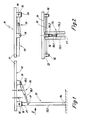
- the table 10 shown in FIG. 1 has a table top 11, on the underside 12 of which a double table leg 13 is arranged at both longitudinal ends of the table 10.
- the two individual legs 13.1 and 13.2 of the double table legs which initially run parallel to one another and end in feet 14 directed outwards, are supported with their upper ends on a bearing rod 15, which is supported by three bearing blocks 16 shown in FIG. 2 on the underside 12 of the table top is fixed at a distance a .
- a connecting rod 17 is arranged at a distance from the bearing rod 15, on which the end of the piston rod 18.1 of a gas spring 18 is articulated.
- the cylinder part 18.2 of the gas spring is coupled to an articulation point 19 which is arranged on the table top 11 at a distance b from the underside 12 of the table top.
- the double table legs 13 can be pivoted against the force of the gas springs 18 between their two end positions shown in FIG. 1, the gas spring exerting a prestress on the double table legs in each of these two end positions.
- this pretension is achieved in that the distance b of the gas spring articulation point 19 from the underside the table top 12 is greater than the corresponding distance a of the bearing rod 15, whereby an over-center position of the gas spring 18 is achieved.
- the underside of the bearing blocks 16 serves in a known manner as a stacking surface for the tables and is provided with a corrugated rubber covering 20 for this purpose.
- FIG. 3 to 5 show a mechanical locking device for the gas spring 18. It consists of a latch bolt 21 which forms with its free end a locking lug 21.1 which cooperates with the end of the cylinder part 18.2 of the gas spring 18.
- the latch bolt lever 21 is connected at its bearing end to a bearing sleeve 22 which is arranged concentrically on the connecting rod 17 to which the end of the piston rod 18.1 of the gas spring 18 is articulated.
- the bearing sleeve 22 is provided with an elongated hole 23 through which the piston rod 18.1 projects. Through the elongated hole 23 and the piston rod 18.1, the pivoting range of the latch bolt 21 is limited.
- Fig. 3 shows the latch bolt 21 in its locked position.
- the latch bolt lever 21 falls into its locking position due to its own weight. If the table is rotated by 180 ° according to FIG. 4 so that the underside 12 of the table top 11 points upward, the latch bolt 21 according to FIG. 4 falls back into its release position, so that the table legs move into the position shown in FIG. apparent transport position can be folded.
- the latch bolt lever 21 has a channel-shaped cross section in the region of its bolt nose 21.1, so that it partially surrounds the piston rod 18.1 in the locked position and therefore cannot be pushed laterally out of its locked position.
Landscapes
- Tables And Desks Characterized By Structural Shape (AREA)
Applications Claiming Priority (2)
| Application Number | Priority Date | Filing Date | Title |
|---|---|---|---|
| DE9002759U | 1990-03-09 | ||
| DE9002759U DE9002759U1 (de) | 1990-03-09 | 1990-03-09 | Tisch mit klappbaren Tischbeinen |
Publications (2)
| Publication Number | Publication Date |
|---|---|
| EP0462313A2 true EP0462313A2 (fr) | 1991-12-27 |
| EP0462313A3 EP0462313A3 (en) | 1992-02-26 |
Family
ID=6851784
Family Applications (1)
| Application Number | Title | Priority Date | Filing Date |
|---|---|---|---|
| EP19900119970 Withdrawn EP0462313A3 (en) | 1990-03-09 | 1990-10-18 | Table with folding legs |
Country Status (2)
| Country | Link |
|---|---|
| EP (1) | EP0462313A3 (fr) |
| DE (1) | DE9002759U1 (fr) |
Cited By (3)
| Publication number | Priority date | Publication date | Assignee | Title |
|---|---|---|---|---|
| EP0611633A1 (fr) * | 1993-02-18 | 1994-08-24 | SORTIMO INTERNATIONAL AUSRÜSTUNGSSYSTEME FÜR SERVICEFAHRZEUGE GmbH | Etabli pliable |
| CN107684260A (zh) * | 2017-08-14 | 2018-02-13 | 安徽德琳环保发展(集团)有限公司 | 一种家具的支脚 |
| CN108741658A (zh) * | 2018-06-21 | 2018-11-06 | 郑州默尔电子信息技术有限公司 | 一种桌腿便于折叠伸缩的笔记本电脑桌 |
Family Cites Families (3)
| Publication number | Priority date | Publication date | Assignee | Title |
|---|---|---|---|---|
| DE8312428U1 (de) * | 1983-04-27 | 1983-10-20 | Herbert Grüttner GmbH & Co KG, 4924 Barntrup | Klapptischbeschlag |
| FR2609382B1 (fr) * | 1987-01-14 | 1990-10-12 | Craipeau Gaetan | Table du type escamotable |
| DE8804868U1 (de) * | 1988-04-14 | 1988-05-26 | Paschen Entwicklung & Design GmbH, 4724 Wadersloh | Tisch, insbesondere Schreibtisch |
-
1990
- 1990-03-09 DE DE9002759U patent/DE9002759U1/de not_active Expired - Lifetime
- 1990-10-18 EP EP19900119970 patent/EP0462313A3/de not_active Withdrawn
Cited By (3)
| Publication number | Priority date | Publication date | Assignee | Title |
|---|---|---|---|---|
| EP0611633A1 (fr) * | 1993-02-18 | 1994-08-24 | SORTIMO INTERNATIONAL AUSRÜSTUNGSSYSTEME FÜR SERVICEFAHRZEUGE GmbH | Etabli pliable |
| CN107684260A (zh) * | 2017-08-14 | 2018-02-13 | 安徽德琳环保发展(集团)有限公司 | 一种家具的支脚 |
| CN108741658A (zh) * | 2018-06-21 | 2018-11-06 | 郑州默尔电子信息技术有限公司 | 一种桌腿便于折叠伸缩的笔记本电脑桌 |
Also Published As
| Publication number | Publication date |
|---|---|
| EP0462313A3 (en) | 1992-02-26 |
| DE9002759U1 (de) | 1990-05-10 |
Similar Documents
| Publication | Publication Date | Title |
|---|---|---|
| CH668397A5 (de) | Allseitig geschlossene uebergangseinrichtung zwischen zwei gekuppelten fahrzeugen oder fahrzeugteilen. | |
| DE3436358C2 (fr) | ||
| DE1220276B (de) | Ausschwingbare Trittstufe fuer Kraftfahrzeuge | |
| DE19837987A1 (de) | Tisch mit einer Tischplatte | |
| DE3323780A1 (de) | Hoehenverstellbarer tisch oder dergleichen | |
| DE9002759U1 (de) | Tisch mit klappbaren Tischbeinen | |
| DE8021315U1 (de) | Klapptisch | |
| DE4106648C2 (de) | Klapptisch und Klappfußgelenk | |
| DE2318815C2 (de) | Hochklappbares Liegemöbel mit Tisch | |
| DE2415572B2 (de) | Möbel-, insbesondere Tischgestell | |
| DE2119077C3 (de) | Mehrschüssige Rollenbahn | |
| DE102004004238B4 (de) | Klapptisch, Verwendung eines Klapptisches in Klappstellung, Stehtisch | |
| DE2508726A1 (de) | Klapptisch | |
| EP0043102B1 (fr) | Charnière divisible pour ridelles de véhicules de transport de charges | |
| DE8804868U1 (de) | Tisch, insbesondere Schreibtisch | |
| DE2802177A1 (de) | Klappbarer wandtisch | |
| DE19705887B4 (de) | Klappbarer Bügeltisch | |
| DE2435635C3 (de) | Höhenverstellbarer Tisch, insbesondere Bügeltisch | |
| DE202011109084U1 (de) | Klapptisch | |
| EP2256241B1 (fr) | Chassis de support pour une table à repasser | |
| DE102020118261B4 (de) | Fahrbarer Kran mit Klappspitzenfangvorrichtung sowie Klappspitze für einen solchen Kran | |
| WO2012065776A1 (fr) | Table de travail, en particulier pour les ateliers | |
| DE29501656U1 (de) | Tischtennisplatte | |
| AT375238B (de) | Erntewagen | |
| DE19853327A1 (de) | Klappbare Tischtennis-Tischhälfte |
Legal Events
| Date | Code | Title | Description |
|---|---|---|---|
| PUAI | Public reference made under article 153(3) epc to a published international application that has entered the european phase |
Free format text: ORIGINAL CODE: 0009012 |
|
| AK | Designated contracting states |
Kind code of ref document: A2 Designated state(s): AT CH DE FR GB IT LI |
|
| PUAL | Search report despatched |
Free format text: ORIGINAL CODE: 0009013 |
|
| AK | Designated contracting states |
Kind code of ref document: A3 Designated state(s): AT CH DE FR GB IT LI |
|
| STAA | Information on the status of an ep patent application or granted ep patent |
Free format text: STATUS: THE APPLICATION IS DEEMED TO BE WITHDRAWN |
|
| 18D | Application deemed to be withdrawn |
Effective date: 19920827 |