EP0611633A1 - Etabli pliable - Google Patents
Etabli pliable Download PDFInfo
- Publication number
- EP0611633A1 EP0611633A1 EP94101888A EP94101888A EP0611633A1 EP 0611633 A1 EP0611633 A1 EP 0611633A1 EP 94101888 A EP94101888 A EP 94101888A EP 94101888 A EP94101888 A EP 94101888A EP 0611633 A1 EP0611633 A1 EP 0611633A1
- Authority
- EP
- European Patent Office
- Prior art keywords
- work plate
- workbench according
- swivel joint
- workbench
- leg
- Prior art date
- Legal status (The legal status is an assumption and is not a legal conclusion. Google has not performed a legal analysis and makes no representation as to the accuracy of the status listed.)
- Withdrawn
Links
- 230000000295 complement effect Effects 0.000 claims description 3
- NJPPVKZQTLUDBO-UHFFFAOYSA-N novaluron Chemical compound C1=C(Cl)C(OC(F)(F)C(OC(F)(F)F)F)=CC=C1NC(=O)NC(=O)C1=C(F)C=CC=C1F NJPPVKZQTLUDBO-UHFFFAOYSA-N 0.000 abstract description 2
- 238000006243 chemical reaction Methods 0.000 description 2
- 229910052751 metal Inorganic materials 0.000 description 2
- 239000002184 metal Substances 0.000 description 2
- 150000002739 metals Chemical class 0.000 description 2
- 238000010276 construction Methods 0.000 description 1
- 238000011161 development Methods 0.000 description 1
- 230000018109 developmental process Effects 0.000 description 1
- 238000009434 installation Methods 0.000 description 1
- 239000000463 material Substances 0.000 description 1
- 239000002689 soil Substances 0.000 description 1
- 239000007787 solid Substances 0.000 description 1
- 229910001220 stainless steel Inorganic materials 0.000 description 1
- 239000002023 wood Substances 0.000 description 1
Images

Classifications
-
- B—PERFORMING OPERATIONS; TRANSPORTING
- B25—HAND TOOLS; PORTABLE POWER-DRIVEN TOOLS; MANIPULATORS
- B25H—WORKSHOP EQUIPMENT, e.g. FOR MARKING-OUT WORK; STORAGE MEANS FOR WORKSHOPS
- B25H1/00—Work benches; Portable stands or supports for positioning portable tools or work to be operated on thereby
- B25H1/02—Work benches; Portable stands or supports for positioning portable tools or work to be operated on thereby of table type
- B25H1/04—Work benches; Portable stands or supports for positioning portable tools or work to be operated on thereby of table type portable
-
- B—PERFORMING OPERATIONS; TRANSPORTING
- B25—HAND TOOLS; PORTABLE POWER-DRIVEN TOOLS; MANIPULATORS
- B25H—WORKSHOP EQUIPMENT, e.g. FOR MARKING-OUT WORK; STORAGE MEANS FOR WORKSHOPS
- B25H5/00—Tool, instrument or work supports or storage means used in association with vehicles; Workers' supports, e.g. mechanics' creepers
Definitions
- the invention relates to a foldable workbench for attachment to a carrier, in particular on a motor vehicle.
- the invention is therefore based on the object of creating a workbench which takes up little space when not in use. This object is achieved by a foldable workbench with the features of claim 1. Advantageous further developments are the subject of the subclaims.
- the workbench consists of a work plate that can be folded up or down, which can be attached to a carrier, for example a vehicle, by means of a bearing block.
- the bearing block permits horizontal attachment, for example on a base plate, and, in a lighter version, vertical attachment, for example on a side wall of the vehicle.
- the work plate is pivotally attached to the bearing block via a first swivel joint. It can thus be pivoted from a vertical, preferably folded up, position into a horizontal working position.
- a supporting leg mounted on the work plate via a second swivel joint folds out into a vertical position, whereby the work plate is supported on the floor in the horizontal position.
- the leg Since the soil conditions are often not known, e.g. if the work surface is folded away from the vehicle to the outside, the leg must be adjustable in length in order to ensure a horizontal position of the work surface even on uneven terrain.
- the adjustability of the length of the supporting leg is particularly important, since the heights of the loading areas are different for all types of vehicles and as a result the worktop can always be placed horizontally.
- the first swivel joint is preferably arranged on the bearing block in the region of a first edge and the second swivel joint in the region of the second edge of the work plate facing away from this edge. In this way, a very secure support of the work plate is achieved, which allows good work on the entire area of the work plate without the work plate yielding elastically.
- a bearing for a gas pressure spring which is held at its other end on the bearing block, is preferably arranged on the work plate in the area between the two swivel joints.
- the bearing for the gas pressure springs is preferably located below the work plate and is arranged such that the gas pressure spring or the gas pressure springs do not protrude laterally beyond the work plate.
- the gas pressure springs are intended to facilitate lifting the table into the vertical position and, on the other hand, to prevent the plate from knocking down when swiveling down.
- the spring force of the gas pressure springs is dimensioned so that they hold the work plate in the rest position when it is folded up.
- the supporting leg has at its end on the bearing side a latching surface which interacts with a complementary latching surface arranged on the workpiece side.
- a vertical position of the table leg is determined relative to the work surface.
- the support leg is preferably spread out like a bracket towards its end on the bearing side, the ends of the bracket being penetrated by an axis, the ends of which are in turn rotatably supported in brackets which are mounted on the work plate.
- These brackets have an elongated hole that extends perpendicular to the worktop.
- the main leg is not only rotatable in the brackets, but also longitudinally displaceable perpendicular to the work plate.
- One or more springs are preferably arranged between the axis of the support leg and the work plate, which pull the axis towards the work plate, so that the locking surfaces of the support leg and the work plate can interlock. This mechanism ensures when swiveling down the work plate that the locking surfaces between the work plate and the support leg interlock.
- the worktop can be locked using a safety lever, e.g. in the manner of a spring clip, by means of which the table leg is fixed in the pivoted-in position when the work surface is pivoted up into the vertical position. This fixation prevents the table leg from swinging out during load change reactions of the motor vehicle and injuring people or objects.
- a safety lever e.g. in the manner of a spring clip
- the first swivel joint for mounting the work plate on the bearing block is preferably spaced somewhat from the first edge of the work plate, so that the work plate projects slightly beyond the bearing.
- This protruding part can be used as a contact surface, which comes into engagement with a contact surface formed on the bearing block, in order to fix a vertical, pivoted-up rest position of the work plate.
- the support against pivoting in the other direction can be formed by the gas pressure spring. However, additional measures can be taken to secure the vertical position of the work plate.
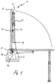
- the workbench 10 consists of a bearing block 12 which is connected to a work plate 16 via a first swivel joint 14.
- the first swivel joint 14 is arranged in the region of a first edge 18 of the work plate 16.
- a second swivel joint 22 is arranged, on which a supporting leg 24 is rotatably held.
- bearings 26 for fastening gas pressure springs 28 are arranged on the underside of the work plate 16, the other ends of which are supported on the bearing block 12.
- two parallel gas pressure springs 28 are used to support the work plate 16, so that even if a gas pressure spring fails, a safe swiveling down or a relief when swiveling the work plate up is ensured.
- the supporting leg 24 is freely rotatable in the second swivel joint 22 in the swiveled-up position and when swiveled down. When placed on the floor, however, as is explained in more detail with reference to FIG. 2, it is fixed in its position perpendicular to the work plate 16.
- the second swivel joint 22 consists of two brackets 32 on the workpiece side, which have elongated holes 34 running perpendicular to the workpiece plate 16. These are penetrated by an axis 36 which is connected to the end 38 of the supporting leg 24 which is widened like a bow. At this end 38, which is widened like a bow, a preferably cylindrical foot 40 is held so as to be adjustable in the axial direction.
- the length of the support leg 24 can hereby be adapted to different ground conditions.
- the supporting leg 24 has a locking surface 42 which, in the vertical position of the supporting leg 24, cooperates with a complementary locking surface 44 on the connecting web of the bracket 32 when the supporting plate 24 rests on the supporting leg 24.
- the axis 36 is namely pulled by one, possibly also two springs to the work plate 16 in the direction of the end of the elongated hole 34 facing the work plate 16. This prevents the leg 24 from rotating freely in the first swivel joint 22 while the work plate is folded into the working position.
- the work plate 16 cannot be brought out of its horizontal position even if a force acts on the supporting leg in the pivoting direction of the supporting leg, for example if a workpiece falls against the supporting leg.
- the work position of the workbench can also be stabilized by a second stop surface on the bearing block and / or by stops in the area of the gas pressure damper.
- a spring clip 48 is provided, by means of which the supporting leg 24 is fixed in its position parallel to the work plate 16.
- the work plate is preferably formed from a suitable wood or plastic.
- the workbench is suitable for installation in the home, on site on construction sites, on workshop trolleys and vehicles in which space-saving storage of a workbench is required.
Landscapes
- Engineering & Computer Science (AREA)
- Mechanical Engineering (AREA)
- Workshop Equipment, Work Benches, Supports, Or Storage Means (AREA)
- Tables And Desks Characterized By Structural Shape (AREA)
- Passenger Equipment (AREA)
- Forklifts And Lifting Vehicles (AREA)
Applications Claiming Priority (2)
| Application Number | Priority Date | Filing Date | Title |
|---|---|---|---|
| DE4305029 | 1993-02-18 | ||
| DE19934305029 DE4305029A1 (de) | 1993-02-18 | 1993-02-18 | Klappbare Werkbank |
Publications (1)
| Publication Number | Publication Date |
|---|---|
| EP0611633A1 true EP0611633A1 (fr) | 1994-08-24 |
Family
ID=6480805
Family Applications (1)
| Application Number | Title | Priority Date | Filing Date |
|---|---|---|---|
| EP94101888A Withdrawn EP0611633A1 (fr) | 1993-02-18 | 1994-02-08 | Etabli pliable |
Country Status (3)
| Country | Link |
|---|---|
| EP (1) | EP0611633A1 (fr) |
| JP (1) | JPH0769115A (fr) |
| DE (1) | DE4305029A1 (fr) |
Cited By (9)
| Publication number | Priority date | Publication date | Assignee | Title |
|---|---|---|---|---|
| DE29618620U1 (de) * | 1996-10-25 | 1997-09-25 | Barnert, Reinhard, 49509 Recke | Kombi-Werkschrank mit integrierter Arbeitsplatte, schwenkbar |
| GB2325193A (en) * | 1997-05-16 | 1998-11-18 | Harris Robert Charles | Folding workbench |
| EP0911121A1 (fr) * | 1997-10-22 | 1999-04-28 | SORTIMO INTERNATIONAL AUSRÜSTUNGSSYSTEME FÜR SERVICEFAHRZEUGE GmbH | Table de travail repliable, notamment incorporée dans un véhicule de service |
| CN104647328A (zh) * | 2014-06-21 | 2015-05-27 | 柳州聚龙科技有限公司 | 车载工具箱 |
| CN104691399A (zh) * | 2015-03-13 | 2015-06-10 | 徐光� | 移动式汽车维修保养工程车 |
| CN110562565A (zh) * | 2019-08-30 | 2019-12-13 | 河南中烟工业有限责任公司 | 可收放的烟草制品置放平台 |
| CN114834368A (zh) * | 2019-03-11 | 2022-08-02 | 说故事的人陆地有限责任公司 | 休闲车辆改装系统 |
| US12036660B2 (en) | 2020-08-07 | 2024-07-16 | Techtronic Cordless Gp | Modular storage system |
| US12570438B2 (en) | 2022-07-11 | 2026-03-10 | Milwaukee Electric Tool Corporation | Mobile storage for modular systems |
Families Citing this family (8)
| Publication number | Priority date | Publication date | Assignee | Title |
|---|---|---|---|---|
| DE10004957A1 (de) * | 2000-02-04 | 2001-08-16 | Wilhelm Bott Gmbh & Co Kg | Stützfuß, Arbeitsplatte mit einem derartigen Stützfuß sowie Werkstatteinrichtung zum Einbau in ein Fahrzeug |
| DE10050849B4 (de) * | 2000-10-13 | 2005-08-11 | Karl-Walter Herbert | Einrichtung zur Halterung eines Arbeitsgerätes im Fahrgastraum eines Kraftfahrzeuges |
| JP4050092B2 (ja) * | 2002-05-22 | 2008-02-20 | 日本曹達株式会社 | 車両点検棟設備 |
| JP6204013B2 (ja) | 2011-10-24 | 2017-09-27 | 日精エー・エス・ビー機械株式会社 | ブロー成形機 |
| DE202014103283U1 (de) | 2014-07-16 | 2015-10-23 | Sortimo International Gmbh | Vorrichtung zur Befestigung eines Schraubstocks |
| DE102014109992A1 (de) | 2014-07-16 | 2016-01-21 | Sortimo International Gmbh | Vorrichtung zur Befestigung eines Schraubstocks |
| KR102143090B1 (ko) | 2019-12-17 | 2020-08-10 | 김진만 | 다목적 커팅기 테이블 |
| DE102020109301A1 (de) | 2020-04-03 | 2021-10-07 | Sortimo International Gmbh | Klappbare Werkbankanordnung |
Citations (8)
| Publication number | Priority date | Publication date | Assignee | Title |
|---|---|---|---|---|
| US4155609A (en) * | 1977-09-08 | 1979-05-22 | Williams Furnace Company | Wall-hung cabinet arrangement |
| US4452151A (en) * | 1981-12-09 | 1984-06-05 | Jarrard George A | Trunk lid folding table |
| US4494465A (en) * | 1983-11-01 | 1985-01-22 | Fick Jr Charles M | Table for use with automobile trunks and the like |
| GB2180494A (en) * | 1985-09-11 | 1987-04-01 | William Henry Billington | A portable folding work-frame |
| US4735392A (en) * | 1987-01-30 | 1988-04-05 | Lisle Corporation | Collapsible support platform |
| WO1988006076A1 (fr) * | 1987-02-13 | 1988-08-25 | Inventions To Industry Limited | Etabli pour vehicule automobile |
| DE8913982U1 (de) * | 1989-11-28 | 1990-02-08 | Fischer, Knuth, Dipl.-Designer, 3500 Kassel | Werkbank |
| EP0462313A2 (fr) * | 1990-03-09 | 1991-12-27 | JAKOB GAUGER SÖHNE STUHL- U. TISCHFABRIK INNENAUSBAU GMBH & Co. | Table à pieds pliants |
-
1993
- 1993-02-18 DE DE19934305029 patent/DE4305029A1/de not_active Ceased
-
1994
- 1994-02-01 JP JP2880794A patent/JPH0769115A/ja active Pending
- 1994-02-08 EP EP94101888A patent/EP0611633A1/fr not_active Withdrawn
Patent Citations (8)
| Publication number | Priority date | Publication date | Assignee | Title |
|---|---|---|---|---|
| US4155609A (en) * | 1977-09-08 | 1979-05-22 | Williams Furnace Company | Wall-hung cabinet arrangement |
| US4452151A (en) * | 1981-12-09 | 1984-06-05 | Jarrard George A | Trunk lid folding table |
| US4494465A (en) * | 1983-11-01 | 1985-01-22 | Fick Jr Charles M | Table for use with automobile trunks and the like |
| GB2180494A (en) * | 1985-09-11 | 1987-04-01 | William Henry Billington | A portable folding work-frame |
| US4735392A (en) * | 1987-01-30 | 1988-04-05 | Lisle Corporation | Collapsible support platform |
| WO1988006076A1 (fr) * | 1987-02-13 | 1988-08-25 | Inventions To Industry Limited | Etabli pour vehicule automobile |
| DE8913982U1 (de) * | 1989-11-28 | 1990-02-08 | Fischer, Knuth, Dipl.-Designer, 3500 Kassel | Werkbank |
| EP0462313A2 (fr) * | 1990-03-09 | 1991-12-27 | JAKOB GAUGER SÖHNE STUHL- U. TISCHFABRIK INNENAUSBAU GMBH & Co. | Table à pieds pliants |
Non-Patent Citations (2)
| Title |
|---|
| DATABASE WPI Week 8506, Derwent World Patents Index; AN 85-037422 * |
| DATABASE WPI Week 9201, Derwent World Patents Index; AN 92-000774 * |
Cited By (12)
| Publication number | Priority date | Publication date | Assignee | Title |
|---|---|---|---|---|
| DE29618620U1 (de) * | 1996-10-25 | 1997-09-25 | Barnert, Reinhard, 49509 Recke | Kombi-Werkschrank mit integrierter Arbeitsplatte, schwenkbar |
| GB2325193A (en) * | 1997-05-16 | 1998-11-18 | Harris Robert Charles | Folding workbench |
| EP0911121A1 (fr) * | 1997-10-22 | 1999-04-28 | SORTIMO INTERNATIONAL AUSRÜSTUNGSSYSTEME FÜR SERVICEFAHRZEUGE GmbH | Table de travail repliable, notamment incorporée dans un véhicule de service |
| DE19746859A1 (de) * | 1997-10-22 | 1999-05-06 | Sortimo Int Gmbh | Klappbare Werkbank, insbesondere zum Einbau in Servicefahrzeuge |
| DE19746859C2 (de) * | 1997-10-22 | 2001-06-07 | Sortimo Internat Ausruestungss | Klappbare Werkbank, insbesondere zum Einbau in Servicefahrzeuge |
| CN104647328A (zh) * | 2014-06-21 | 2015-05-27 | 柳州聚龙科技有限公司 | 车载工具箱 |
| CN104691399A (zh) * | 2015-03-13 | 2015-06-10 | 徐光� | 移动式汽车维修保养工程车 |
| CN104691399B (zh) * | 2015-03-13 | 2017-02-22 | 赛浪车联汽车科技(北京)股份有限公司 | 移动式汽车维修保养工程车 |
| CN114834368A (zh) * | 2019-03-11 | 2022-08-02 | 说故事的人陆地有限责任公司 | 休闲车辆改装系统 |
| CN110562565A (zh) * | 2019-08-30 | 2019-12-13 | 河南中烟工业有限责任公司 | 可收放的烟草制品置放平台 |
| US12036660B2 (en) | 2020-08-07 | 2024-07-16 | Techtronic Cordless Gp | Modular storage system |
| US12570438B2 (en) | 2022-07-11 | 2026-03-10 | Milwaukee Electric Tool Corporation | Mobile storage for modular systems |
Also Published As
| Publication number | Publication date |
|---|---|
| JPH0769115A (ja) | 1995-03-14 |
| DE4305029A1 (de) | 1994-08-25 |
Similar Documents
| Publication | Publication Date | Title |
|---|---|---|
| EP0611633A1 (fr) | Etabli pliable | |
| EP0647499B1 (fr) | Serre-joints | |
| DE3719730C2 (fr) | ||
| WO1996012423A1 (fr) | Table | |
| DE19531502A1 (de) | Zusammenlegbares Dreibeinstativ | |
| DE20118884U1 (de) | Mit Füßen versehene, verschwenkbare Platte | |
| WO1999055554A1 (fr) | Dispositif de support reglable pour ordinateur de bord monte dans un vehicule automobile, en particulier pour ordinateur portatif ou bloc-notes | |
| DE60026740T2 (de) | Befestigungsvorrichtung zur abnehmbaren halterung eines tisches | |
| DE3007611C2 (de) | Baukastenwerktisch für die Aufnahme einer Nähmaschine | |
| EP0911121B1 (fr) | Table de travail repliable, notamment incorporée dans un véhicule de service | |
| DE20008292U1 (de) | Rastbefestigung für eine Schwinglade | |
| DE20202769U1 (de) | Einstellbare Halteeinrichtung für Bordcomputer in Kraftfahrzeugen, insbesondere für Laptop- oder Notebook-Computer, mit basisseitiger Befestigung im Sitzkonsolenbereich | |
| DE9302379U1 (de) | Klappbare Werkbank | |
| DE2814931A1 (de) | Haltevorrichtung fuer eine dreidimensionale struktur | |
| DE8021315U1 (de) | Klapptisch | |
| DE102023114864A1 (de) | Fahrradreparaturständer | |
| EP0019243B1 (fr) | Pied pour écrans de projection | |
| DE8705173U1 (de) | Multivariabler Tisch | |
| EP0864464A2 (fr) | Triangle de signalisation pliable | |
| DE8423345U1 (de) | Werk- und arbeitsbank | |
| DE4316433C2 (de) | Vorrichtung zur Halterung von Notenblättern | |
| DE10216450B4 (de) | Bedienaufsatz | |
| DE29615058U1 (de) | Vorrichtung zur Montage von Deckenplatten | |
| DE4039469C2 (de) | Klappbares Gestell mit einer Platte, insbesondere Maschinentisch für Heimwerker | |
| DE8913982U1 (de) | Werkbank |
Legal Events
| Date | Code | Title | Description |
|---|---|---|---|
| PUAI | Public reference made under article 153(3) epc to a published international application that has entered the european phase |
Free format text: ORIGINAL CODE: 0009012 |
|
| AK | Designated contracting states |
Kind code of ref document: A1 Designated state(s): AT CH DE FR IT LI NL |
|
| 17P | Request for examination filed |
Effective date: 19950224 |
|
| 17Q | First examination report despatched |
Effective date: 19970407 |
|
| STAA | Information on the status of an ep patent application or granted ep patent |
Free format text: STATUS: THE APPLICATION IS DEEMED TO BE WITHDRAWN |
|
| 18D | Application deemed to be withdrawn |
Effective date: 19980207 |