EP0462428A2 - Fernsteueranordnung zur Steuerung eines Fernsehempfängers - Google Patents
Fernsteueranordnung zur Steuerung eines Fernsehempfängers Download PDFInfo
- Publication number
- EP0462428A2 EP0462428A2 EP91108707A EP91108707A EP0462428A2 EP 0462428 A2 EP0462428 A2 EP 0462428A2 EP 91108707 A EP91108707 A EP 91108707A EP 91108707 A EP91108707 A EP 91108707A EP 0462428 A2 EP0462428 A2 EP 0462428A2
- Authority
- EP
- European Patent Office
- Prior art keywords
- light
- remote control
- control device
- unit
- code
- Prior art date
- Legal status (The legal status is an assumption and is not a legal conclusion. Google has not performed a legal analysis and makes no representation as to the accuracy of the status listed.)
- Granted
Links
Images


Classifications
-
- G—PHYSICS
- G08—SIGNALLING
- G08C—TRANSMISSION SYSTEMS FOR MEASURED VALUES, CONTROL OR SIMILAR SIGNALS
- G08C19/00—Electric signal transmission systems
- G08C19/30—Electric signal transmission systems in which transmission is by selection of one or more conductors or channels from a plurality of conductors or channels
-
- H—ELECTRICITY
- H03—ELECTRONIC CIRCUITRY
- H03J—TUNING RESONANT CIRCUITS; SELECTING RESONANT CIRCUITS
- H03J9/00—Remote-control of tuned circuits; Combined remote-control of tuning and other functions, e.g. brightness, amplification
- H03J9/06—Remote-control of tuned circuits; Combined remote-control of tuning and other functions, e.g. brightness, amplification using electromagnetic waves other than radio waves, e.g. light
Definitions
- This invention relates to a remote control system for controlling a television receiver or the like.
- a conventional remote control system for controlling each of the direct view receivers has a similar drawback arising from the fact that the remote control device should be manipulated by alternately viewing an image shown on the screen thereof and characters printed on the remote control device.
- the present invention is accomplished to eliminate the above described drawbacks of the conventional remote control system.
- a remote control system having a remote control device which comprises a diaphragm for limiting the cross section of a beam of light incident thereon to a small area, at least two light receiving elements, which are arranged such that an area, on which the incident light impinges, of each of the light receiving elements changes depending on an angle of incidence of the incident light, for receiving the incident light passing through the diaphragm, a switching circuit for selectively inputting outputs of necessary ones of the light receiving elements, an intensity-of-received-light detecting portion for detecting the intensity of light received by each of the light receiving elements from outputs of the switching circuit and a calculating portion for calculating a ratio of the intensity of light received by one of each pair of the light receiving elements to that of light by the other light receiving element from the intensities of light detected by the intensity-of-received-light detecting portion.
- the remote control device of this remote control system light coming from an external light source is received by at least two light receiving elements through the diaphragm. Then, received light signals emitted by the respective light receiving elements are selected by the switching circuit and are serially detected by the intensity-of-light detecting means. Further, the intensity of light received by each of the light receiving elements is measured by the intensity-of-light detecting means. Subsequently, a ratio of the intensity of light received by one of each pair of the light receiving elements to that of light received by the other of each pair thereof is calculated by the calculating means in order to indirectly detect the direction of an operating portion of the remote control device toward the light source. Thereby, the direction of the operating portion toward the light source is changed within a predetermined range of an angle. Further, by turning the operating portion toward a specific direction, a corresponding specific function or operation is indicated.
- a remote control system of which the construction is similar to that of the remote control system of the first aspect of the present invention except that a lens is provided instead of the diaphragm.
- a remote control system including the composing elements of the remote control system according to the first or second aspect of the present invention
- the remote control device further comprises a remote-control-code generating means for generating a remote control code corresponding to output data of the calculating means and for outputting a signal representing the generated remote code and a first light emitting element for emitting light representing the signal representing the remote control code generated by the remote-control-code generating means
- the unit comprises a remote-control-code receiving element for receiving the light emitted from said first light emitting element of the remote control device, a remote-control-code interpreting and discriminating portion for interpreting and discriminating the remote control code indicated by the signal represented by the light received by the remote-control-code receiving element, a second light emitting element for emitting light representing a response signal to at least two of the light emitting elements of the remote control device and a light modulating means for driving the second light emitting element in such a manner to modulate
- the light emitting element is provided in the unit such as a television receiver to be controlled.
- the operating portion of the remote control device is turned toward the unit to be controlled. Then, the operating portion is shifted around a line drawn from the operating portion to the center of the screen of the unit to be controlled within a small range of an angle with respect to the center of the screen of the unit to be controlled. Thereafter, light is emitted from the light emitting element of the unit to be controlled. Then, similarly as in case of the remote control system of the first aspect of the present invention, the direction of the operating portion toward the light source is detected by regarding the light emitted from the light emitting element of the unit as light from the external light source.
- data indicating the detected direction is converted by the remote-control-code generating means into a remote control code.
- a light signal representing the remote control code is transmitted by the light emitting element of the remote control device.
- the thus transmitted light signal is received by the remote-control-code receiving element provided in the unit to be controlled.
- information represented by the received signal is interpreted by the remote-control-code interpreting and discriminating portion. Thereby, the direction in which the operating portion is oriented can be found by the unit to be controlled.
- the representation of a specific operation displayed on the screen of the unit can be indicated by turning the operating portion toward the unit in a corresponding specific direction within a predetermined range of an angle with respect to the line drawn from center of the screen of the unit to an initial position of the operating portion of the remote control device.
- a remote control system having a remote control device and a unit to be controlled by the remote control device, wherein the remote control device comprises a diaphragm means for limiting the cross section of a beam of light incident thereon to a small area, a first light receiving means for receiving the incident light passing through the diaphragm means, the first light receiving means being arranged such that an area, on which the incident light impinges, of the first light receiving means changes depending on an angle of incidence of the incident light, an intensity-of-received-light detecting means for detecting the intensity of light received by the first light receiving means, a position-information generating means for generating position information indicating what position of the unit the remote control device is turned toward from the intensities of light detected by the intensity-of-received-light detecting means, a remote-control-code generating means for generating a remote control code corresponding to output data of the position-information generating means and for outputting
- a remote control system of which the construction is similar to that of the remote control system of the third aspect of the present invention except that a lens means is provided instead of the diaphragm means.
- a remote control system including the composing elements of the remote control system according to the third or fourth aspect of the present invention, wherein the first light receiving means comprises at least two light receiving elements arranged such that an area, on which the incident light impinges, of each of the light receiving elements changes depending on an angle of incidence of the incident light.
- a cursor is first displayed on the screen of the unit such as a television receiver in the direction in which an operating portion of the remote control device is oriented. Then, the cursor can be moved on the screen by shifting the operating portion of the remote control device. Subsequently, a desired operation is selected and performed by depressing a switch provided on the operating portion when the cursor is superposed on the indication of the desired operation on the menu.
- the remote control device of the present invention can be manipulated without seeing the keyboard of the remote control device.
- the movement of a viewer's eyes at the time of manipulating the remote control device can be decreased. Consequently, the remote control device can be very easy to manipulate.
- the operability of the remote control device in the dark can be improved.
- the remote control system of the present invention is very advantageous to practical use.
- a method of performing remote control of a unit by manipulating a remote control device comprising the steps of turning the light emitting element of the remote control device toward the screen of the unit, transmitting a first light signal indicating the start of a remote control operation from a first light emitting element of the remote control device to the unit, displaying a menu of items of operations on the screen of the unit, transmitting a response light signal from the second light emitting element of the unit to the remote control device, generating a control code corresponding to a position on which the light emitted from the first light emitting element of the remote control device currently impinges, on the screen, based on the intensities of light respectively received by light receiving elements of the remote control device, transmitting a second light signal representing the generated code from the first light emitting element of the remote control device to the unit, displaying a cursor at the position corresponding to the control code represented by the second light signal on the screen of the unit, shifting the remote control device
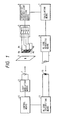
- reference numeral 1 designates an infrared light emitting diode (LED); and 2 a light modulating means for driving the LED 1 by applying an amplitude modulation signal having a frequency of 445 kHz thereto.
- LED infrared light emitting diode
- 2 a light modulating means for driving the LED 1 by applying an amplitude modulation signal having a frequency of 445 kHz thereto.
- These devices together with a light receiving element 10, a remote control code interpreting means 11 and a control means 12 which will be described later, are provided in a unit to be controlled (e.g. , a television receiver).
- a portion composed of elements from a diaphragm or stop 3 to a light emitting element 9 is provided in an operating part of a remote control device.
- the diaphragm 3 is constructed such that only a very-small-area portion 300 transmits light emitted from the LED 1.
- Reference numerals 4a to 4d denote light receiving elements which are positioned just posterior to the diaphragm 3. As shown in FIG. 1, this embodiment employs a combination of the four light receiving elements the respective of which are arranged like a checker pattern and have large light-receiving-areas.
- Reference numeral 5 represents a switching circuit, to which output signals of the four light receiving elements are connected, for selecting one or more light receiving elements from the four elements 4a to 4d and sending light receiving signals outputted from the selected elements to the next stage;
- 6 an intensity-of-received-light determining means (hereunder referred to simply as an intensity determining means) connected to outputs of the switching circuit 5 for quantitatively determining the intensity of light received by the light receiving elements;
- 7 a processing means for processing outputs of the intensity determining means 6;
- 8 a remote-control-code generating means (hereunder referred to simply as a code generating means) for generating a remote control code in accordance with results of operations performed by the processing means 7;
- 9 an infrared LED which is driven in accordance with outputs of the code generating means 8;
- 10 the light receiving element for receiving a light signal from the LED 9;
- 11 the remote control interpreting means for interpreting a remote control code represented by the signal received by the light emitting
- FIG. 2 there is shown a practical example of the circuit of a primary part of the embodiment of FIG. 1.
- the processing means 7 and the code generating means 8 are constructed by a microcomputer 22 and on the other hand the remote control interpreting means 11 and the control means are constructed by a microcomputer 25.
- the microcomputers 22 and 25 are one-chip micorcomputers each of which includes a central processing unit (CPU), a read-only memory (ROM) and a random access memory (RAM) and an input-output (I/0) unit.
- CPU central processing unit
- ROM read-only memory
- RAM random access memory
- I/0 input-output
- reference numeral 26 denotes a CRT controller for showing characters on the screen of a CRT; 27 an RGB video input terminal from which an RGB signal converted by a signal processing circuit (not shown) by using a composite video signal; and an RGB video output terminal from which a signal obtained by the CRT controller 27 by superposing another signal representing character or the like upon the RGB signal.
- a frequency modulating device 24 drives the LED 1 and sends a modulated light signal to the operating portion. Further, a signal issued by the light emitting element 9 is received by the light receiving element 10 and a remote control mode represented by the received signal is read by the microcomputer 25. These operations are controlled by the microcomputer 25 in accordance with a predetermined procedure.
- the diaphragm 3 is positioned immediately prior to the light receiving element 4a to 4d.
- the operating portion into which the diaphragm 3 and the light receiving elements 4a to 4d are integrally incorporated is placed face to face with the LED 1 at an initial position apart therefrom by several meters, light emitted from the LED 1 impinges on the central portion of a group of the light receiving elements 4a to 4d through the diaphragm 3. If the entire operating portion is then shifted upwardly and downwardly, and leftwardly and rightwardly within a range of from - 30 degrees or so to + 30 degrees or so with respect to the direction from the LED 1 to the original position thereof, the relative direction in which light comes from the LED 1 to the operating portion changes.
- the position, on which light from the LED 1 impinges moves on the surface of the light receiving elements 4a to 4d. This results in change of a ratio of the quantity of light received by each of the four light receiving elements 4a to 4d to that received by another one of the elements 4a to 4d.
- the switching circuit 5 the light signals received by the light receiving elements 4a to 4d of which the outputs are selected by the circuit 5 are serially converted into digital data by an analog-to-digital (A/D) converter 20.
- A/D analog-to-digital
- an automatic gain control circuit 19 is inserted prior to the A/D converter 20 in order to compensate change of the intensity of the received light, which is caused by change in distance between the operating portion and the unit to be controlled.
- the digital data sequentially being outputted by the A/D converter 20 and representing the intensity of the light received by each of the selected light receiving elements are read by the microcomputer 22.
- Reference numeral 21 represents a switch, to which the microcomputer 22 is connected for determining whether or not the switch 21 is pressed down, for directing that a remote control operation is started and for selecting an item of the remote control operation.
- Information on the direction of the operating portion is generated by the microcomputer 22 as a remote control code.
- a transistor 23 drives the light emitting element 9 and causes an electric current flow therein, thereby performing a transmission of a signal representing the information on the direction of the operating portion (namely, the remote control code) by using light.
- the transmitted light representing the information on the direction of the operating portion is received by the light receiving element 10 provided in the unit to be controlled. Then, a signal outputted from the light receiving element 10 is connected to the microcomputer 25 which interprets the transmitted remote control code, thereby finding the direction of the operating portion.
- the CRT controller 26 displays a menu which is a list of operation functions such as a picture quality regulation and a sound regulation on the screen of the television receiver as well as a cursor thereon based on the signal transmitted from the operating portion and representing the direction of the operating portion.
- FIGS. 3(A) and 3(B) there are respectively shown an example of an image practically displayed on the screen of the television receiver and another example of an image displayed thereon when the direction of the operating portion is changed.
- FIG. 3(A) illustrates an image displayed on the screen of the television receiver corresponding to the unit to be controlled.
- an operation menu of FIG. 3(A) is displayed by being superposed on an ordinary picture.
- the operation menu as well as a cursor is displayed on the screen as illustrated in FIG. 3(B).
- the position of the cursor is changed such that the cursor is always displayed at a position, which is placed in the direction of the operating portion, on the screen.
- a viewer manipulating the operating portion can feel that when the operating portion is appropriately shifted toward the screen of the television receiver, the cursor moves on the screen in response to the shift of the operating portion.
- a function of selecting a desired item of an operation by depressing the switch 21 again with the cursor put on the indication of the desired item of an operation on the screen is added to the remote control device.
- FIG. 4 there is illustrated a flowchart of a program for performing an operation of the microcomputer 22 provided in the operation portion of the remote control device.
- step 31 When the operating portion is not used, a state of the switch 21 of the operating portion is detected in step 31 and the remote control device is placed in the wait state in this step until the switch 21 is depressed.
- the program advances to step 32 whereupon a remote control code indicating that the switch is depressed is transmitted once to the unit to be controlled.
- the unit to be controlled is adapted to transmit to the operating portion a sequence of pulses for a predetermined time as a response signal. An operation of the unit to be controlled will be described detailedly later.
- the predetermined time is set to be equal to or longer than a time required for performing processings to be performed in steps 34 to 46 which will be described later.
- step 33 the operating portion of the remote control device waits for a response signal in order to determine whether or not the response signal is received within another predetermined period of time.
- the program returns to the step 31 so that the remote control device falls into the wait state once more. This is accomplished to prevent consumption of a battery provided in the remote control device in a meaningless case, for instance, in case where the switch of the operating portion is depressed when the operating portion does not face the unit to be controlled.
- the program advances to step 34.
- step 34 first, the switching circuit 5 is set in such a manner that outputs of all of the light receiving elements 4a, 4b, 4c and 4d are connected to the A/D converter 20. Then, the remote control device is placed in the wait state for a while in step 35 until an operation of the automatic gain control circuit 19 becomes stable. Subsequently, in step 36, the intensity of light received by the light receiving elements is measured. Namely, output data of the A/D converter 20 is read by the microcomputer 22 and is further held therein as data i1.
- step 37 the switching circuit 5 is set in such a fashion that the outputs of all of the light receiving elements 4a, 4b, 4c and 4d are separated from the A/D converter 20.
- step 38 output data of the A/D converter 22 is read by the microcomputer 22 and is held therein as data i2 which indicates a quantity of noises generated in the automatic gain control circuit 19 when the gain of the operating portion is appropriately regulated for the measured intensity of light and is later used for performing an operation.
- the switching circuit 5 is set in step 39 in such a manner to connect only outputs of the light receiving elements 4a and 4c to the A/D converter 20 and subsequently the intensity of light is measured in step 40 similarly as in step 36.
- the result of the measurement is stored in the microcomputer 22 as data i3.
- the switching circuit 5 is set in step 41 in such a manner to connect only outputs of the light receiving elements 4a and 4d to the A/D converter 20 and subsequently the intensity of light is measured in step 42.
- the result of this measurement is stored in the microcomputer 22 as data i4.
- the program preliminarily contains a correspondence table indicating the corresponding relation between values of the deviation x and three columns (namely, a left, center and right columns) each composed of three regions.
- the corresponding relation therebetween is preliminarily determined as follows:
- step 46 it is judged again whether or not the switch 21 of the operating portion is depressed. Incidentally, in case where the switch is kept depressed since it is judged in step 31 that the switch is depressed, it is regarded in step 46 that the switch is not depressed. Only in case where the switch is depressed again after the switch is turned off, it is regarded in step 46 that the switch is depressed.
- step 48 a remote control code is preliminarily assigned to each of the nine regions previously described. Namely, nine remote control codes respectively indicating the nine regions are preliminarily determined.
- step 48 a remote control code indicating one of the regions is transmitted to the unit to be controlled.
- step 47 a remote control code indicating that the switch is depressed is transmitted once to the unit to be controlled. After transmitting this code, the program returns to step 33 whereupon the operating portion waits for a response signal transmitted in response to this code by the unit to be controlled. Thereafter, the above described operations to be performed in a loop comprised of steps 33 to 48 are repeatedly effected.
- FIG. 5 there is illustrated a flowchart of a program for performing an operation of the microcomputer 25 of the unit to be controlled.
- step 61 it is checked in step 61 whether or not a remote control code is presently received. If no remote control code is received, the program advances to step 62 whereupon it is checked whether or not the menu is presently displayed. If the menu is not displayed, it is regarded that the unit to be controlled is in an ordinary wait state. Further, the program returns to step 61 and thus the unit to be controlled waits again for a reception of a remote control code. In contrast, if the menu is displayed, the program advances to step 63 whereupon the menu is erased from the screen. Then, the program returns to step 61 and the unit to be controlled falls into the wait state again.
- the operating portion and the unit to be controlled keep performing the transmission of the remote control codes and the response to the received remote control codes, respectively. Therefore, interruption of transmission of remote control codes can be regarded that the operating portion of the remote control device is not turned toward the unit to be controlled and that namely, a viewer stops controlling the unit to be controlled.
- step 61 In case where it is found in step 61 that a remote control code is received, the program advances to step 64 whereupon the contents of the received remote control code are interpreted. Subsequently, in step 65, it is checked whether or not the received remote control code indicates one of the regions in which the cursor is displayed. If the received remote control code indicates one of the regions, the program advances to step 66 whereupon the menu is presently displayed. If not displayed, the program returns to step 61 because information on the region in which the cursor is displayed is useless when the menu is not displayed on the screen. In contrast, if the menu is displayed, a signal frequency-modulated by using a constant frequency is first transmitted for a predetermined time toward the operating portion in step 67. Then, the cursor is actually displayed in the region indicated by the received remote control code in step 68. Thereafter, the program returns to step 61 and the remote control device waits for the next remote control code.
- step 65 the program advances to step 69 whereupon it is checked whether or not the received remote control code is a code (hereunder referred to as a switch-depressing code) indicating that the switch is depressed. If the received remote control code is the switch-depressing code, the program advances to step 70 whereupon the menu is presently displayed on the screen. If the menu is not displayed on the screen, the program advances to step 71. In case where the switch-depressing code is received when the menu is not displayed, an operation of displaying the menu is performed in response to this code. Thus, in step 71, the menu is displayed.
- a code hereunder referred to as a switch-depressing code
- step 72 a response signal is transmitted to the operating portion. Then, the program returns to step 61, so that the remote control device falls into the wait state.
- this code means that a command indicated at the position at which the cursor is presently displayed in the menu is performed.
- step 73 a response signal is transmitted to the operating portion. Then, a command indicated at the position at which the cursor is presently displayed in the menu is performed in step 74. Thereafter, the program returns to step 61 and thus the remote control device falls into the wait state.
- a viewer in case of applying the present invention to a television receiver, a viewer can select a desired item of operations by first turning the operating portion itself toward the item of the menu displayed on the television receiver and next depressing the switch 21 of the operating portion.
- the remote control device of the present invention a selection of an item of operations is straightforward and therefore the remote control device according to the present invention is easy to manipulate.
- the remote control device of the present invention can be manipulated without seeing the keyboard of the remote control device and namely can be easily manipulated even in the dark.
- a remote control system for controlling a television receiver or the like which has an operating portion including a diaphragm and at least two light receiving elements.
- the remote control system light issued from an external light source is received by the light receiving elements through the diaphragm. Further, the direction in which the operating portion is oriented is detected on the basis of light receiving signals outputted by each of the light receiving elements.
- a cursor is displayed at a position toward which the operating portion is turned on the screen of the unit. Then, the cursor is moved on the screen in response to change in the direction in which the operating portion is oriented. Subsequently, a desired operation is performed by depressing a switch of the operating portion when the cursor is superposed on an indication of the desired operation in a menu displayed on the screen.
- the remote control system can be very easy to manipulate.
Landscapes
- Physics & Mathematics (AREA)
- Electromagnetism (AREA)
- Engineering & Computer Science (AREA)
- Computer Hardware Design (AREA)
- Microelectronics & Electronic Packaging (AREA)
- General Physics & Mathematics (AREA)
- Selective Calling Equipment (AREA)
- Details Of Television Systems (AREA)
- Optical Communication System (AREA)
Applications Claiming Priority (2)
| Application Number | Priority Date | Filing Date | Title |
|---|---|---|---|
| JP2137800A JPH0435365A (ja) | 1990-05-28 | 1990-05-28 | 遠隔操作装置 |
| JP137800/90 | 1990-05-28 |
Publications (3)
| Publication Number | Publication Date |
|---|---|
| EP0462428A2 true EP0462428A2 (de) | 1991-12-27 |
| EP0462428A3 EP0462428A3 (en) | 1992-05-06 |
| EP0462428B1 EP0462428B1 (de) | 1997-04-16 |
Family
ID=15207145
Family Applications (1)
| Application Number | Title | Priority Date | Filing Date |
|---|---|---|---|
| EP91108707A Expired - Lifetime EP0462428B1 (de) | 1990-05-28 | 1991-05-27 | Fernsteueranordnung zur Steuerung eines Fernsehempfängers |
Country Status (7)
| Country | Link |
|---|---|
| US (1) | US5349460A (de) |
| EP (1) | EP0462428B1 (de) |
| JP (1) | JPH0435365A (de) |
| KR (1) | KR940011333B1 (de) |
| CA (1) | CA2043339C (de) |
| DE (1) | DE69125654T2 (de) |
| MY (1) | MY107489A (de) |
Cited By (3)
| Publication number | Priority date | Publication date | Assignee | Title |
|---|---|---|---|---|
| US5532753A (en) * | 1993-03-22 | 1996-07-02 | Sony Deutschland Gmbh | Remote-controlled on-screen audio/video receiver control apparatus |
| EP1100042A3 (de) * | 1999-10-27 | 2001-08-08 | Ken Curran & Associates | Universelle Fernbedienung für Fernseher |
| US7139562B2 (en) | 2002-09-27 | 2006-11-21 | Matsushita Electric Industrial Co., Ltd. | Remote control device |
Families Citing this family (23)
| Publication number | Priority date | Publication date | Assignee | Title |
|---|---|---|---|---|
| JPH0662464A (ja) * | 1992-08-10 | 1994-03-04 | Sony Corp | リモートコントロールシステム |
| JP3382314B2 (ja) * | 1993-08-24 | 2003-03-04 | キヤノン株式会社 | 通信装置及び通信装置の制御方法 |
| US5894278A (en) * | 1994-04-07 | 1999-04-13 | Sony Corporation | Shield plate, electronic appliance equipped with shield plate, remote control system for electronic appliance, and shielding apparatus |
| JP3473988B2 (ja) * | 1994-05-20 | 2003-12-08 | 株式会社ワコム | 情報入力装置 |
| EP1168232B1 (de) * | 1994-06-09 | 2004-03-03 | Corporation for National Research Initiatives | Hinweisvorrichtungsschittstelle |
| US5767919A (en) * | 1994-06-25 | 1998-06-16 | Samsung Electronics Co.,Ltd. | Remote control method and video apparatus for performing the same |
| GB2291497B (en) * | 1994-07-06 | 1998-09-23 | Alps Electric Co Ltd | Relative position detecting device |
| JP3368677B2 (ja) * | 1994-07-18 | 2003-01-20 | カシオ計算機株式会社 | スクリーン装置 |
| US6727887B1 (en) * | 1995-01-05 | 2004-04-27 | International Business Machines Corporation | Wireless pointing device for remote cursor control |
| JP3814904B2 (ja) * | 1996-12-25 | 2006-08-30 | ソニー株式会社 | 位置検出装置及び遠隔操作装置 |
| US6271831B1 (en) | 1997-04-03 | 2001-08-07 | Universal Electronics Inc. | Wireless control and pointer system |
| US6535198B1 (en) | 1999-03-28 | 2003-03-18 | Nongqiang Fan | Remote control for interactive television |
| KR20010001005A (ko) * | 1999-06-01 | 2001-01-05 | 전주범 | 텔레비전의 메뉴 제어 방법 및 그 장치 |
| GB0004811D0 (en) * | 2000-03-01 | 2000-04-19 | Pace Micro Tech Plc | Improvements relating to braodcast date receiving apparatus |
| JP4708581B2 (ja) * | 2000-04-07 | 2011-06-22 | キヤノン株式会社 | 座標入力装置、座標入力指示具及びコンピュータプログラム |
| KR100803585B1 (ko) * | 2001-12-05 | 2008-02-15 | 삼성전자주식회사 | 원격 포인팅 입력 방법 및 그 장치 |
| JP2003283955A (ja) * | 2002-03-26 | 2003-10-03 | Seiko Epson Corp | 画像表示装置、およびコンピュータ読みとり可能なプログラム |
| WO2005119356A2 (en) | 2004-05-28 | 2005-12-15 | Erik Jan Banning | Interactive direct-pointing system and calibration method |
| US9285897B2 (en) | 2005-07-13 | 2016-03-15 | Ultimate Pointer, L.L.C. | Easily deployable interactive direct-pointing system and calibration method therefor |
| JP2007158449A (ja) * | 2005-11-30 | 2007-06-21 | Sharp Corp | リモートコントロールに基づく被制御装置 |
| CN101336055B (zh) * | 2007-06-26 | 2011-04-20 | 青岛海信电器股份有限公司 | 一种电视装置 |
| US20120127012A1 (en) * | 2010-11-24 | 2012-05-24 | Samsung Electronics Co., Ltd. | Determining user intent from position and orientation information |
| KR101573490B1 (ko) * | 2014-10-02 | 2015-12-11 | 레이트론(주) | 광 도파로를 이용한 광신호 송수신 장치 |
Family Cites Families (7)
| Publication number | Priority date | Publication date | Assignee | Title |
|---|---|---|---|---|
| JPS60121347U (ja) * | 1984-01-24 | 1985-08-16 | ソニー株式会社 | 光送受信装置 |
| FR2583197A1 (fr) * | 1985-06-07 | 1986-12-12 | Thomson Csf | Systeme de commande de positionnement d'une marque sur un ecran et application a la commande d'ordres a distance |
| DE3751226T2 (de) * | 1986-11-27 | 1995-12-07 | Fenner David Fenton | Fernsteuerungssysteme. |
| US4745402A (en) * | 1987-02-19 | 1988-05-17 | Rca Licensing Corporation | Input device for a display system using phase-encoded signals |
| DE3828334C2 (de) * | 1988-08-20 | 1994-02-03 | Nokia Unterhaltungselektronik | Fernbedienbares elektrisches Gerät |
| JPH0258994A (ja) * | 1988-08-24 | 1990-02-28 | Matsushita Electric Ind Co Ltd | リモコン位置検出装置 |
| US5045843B1 (en) * | 1988-12-06 | 1996-07-16 | Selectech Ltd | Optical pointing device |
-
1990
- 1990-05-28 JP JP2137800A patent/JPH0435365A/ja active Pending
-
1991
- 1991-05-27 MY MYPI91000915A patent/MY107489A/en unknown
- 1991-05-27 CA CA002043339A patent/CA2043339C/en not_active Expired - Fee Related
- 1991-05-27 EP EP91108707A patent/EP0462428B1/de not_active Expired - Lifetime
- 1991-05-27 DE DE69125654T patent/DE69125654T2/de not_active Expired - Fee Related
- 1991-05-27 KR KR1019910008651A patent/KR940011333B1/ko not_active Expired - Fee Related
-
1993
- 1993-12-30 US US08/176,289 patent/US5349460A/en not_active Expired - Fee Related
Cited By (3)
| Publication number | Priority date | Publication date | Assignee | Title |
|---|---|---|---|---|
| US5532753A (en) * | 1993-03-22 | 1996-07-02 | Sony Deutschland Gmbh | Remote-controlled on-screen audio/video receiver control apparatus |
| EP1100042A3 (de) * | 1999-10-27 | 2001-08-08 | Ken Curran & Associates | Universelle Fernbedienung für Fernseher |
| US7139562B2 (en) | 2002-09-27 | 2006-11-21 | Matsushita Electric Industrial Co., Ltd. | Remote control device |
Also Published As
| Publication number | Publication date |
|---|---|
| DE69125654D1 (de) | 1997-05-22 |
| JPH0435365A (ja) | 1992-02-06 |
| EP0462428A3 (en) | 1992-05-06 |
| EP0462428B1 (de) | 1997-04-16 |
| CA2043339A1 (en) | 1991-11-29 |
| DE69125654T2 (de) | 1997-10-23 |
| US5349460A (en) | 1994-09-20 |
| KR910020620A (ko) | 1991-12-20 |
| KR940011333B1 (ko) | 1994-12-05 |
| CA2043339C (en) | 1996-12-03 |
| MY107489A (en) | 1995-12-30 |
Similar Documents
| Publication | Publication Date | Title |
|---|---|---|
| CA2043339C (en) | Remote control system for controlling a television receiver | |
| KR900002743B1 (ko) | 원격 조작장치 | |
| US5767919A (en) | Remote control method and video apparatus for performing the same | |
| US20020015137A1 (en) | Image display system, image display method, storage medium, and computer program | |
| EP1087327B1 (de) | Präsentationssystem mit einer interaktiven Darstellung | |
| US6963331B1 (en) | Position information input apparatus and method | |
| US8704768B2 (en) | Image processing apparatus and method | |
| US6456276B1 (en) | Apparatus for recognizing pointing position in video display system with remote controller, and a method therefor | |
| EP1082696B1 (de) | Fernsteuerungsanordnung für eine anzeigevorrichtung | |
| WO1997041502A1 (en) | Position determination of a laser pointer in a projection display system | |
| US7443381B2 (en) | Remote control device with button for notifying pointer movement mode | |
| US5877747A (en) | Remote control system with a pointing device | |
| US6317266B1 (en) | Coordinate input apparatus | |
| US5173778A (en) | Television receiver having simplified functional selection and functional adjustment control | |
| JPH0675695A (ja) | カーソル制御装置 | |
| JPH0659807A (ja) | カーソル制御装置 | |
| KR20010026856A (ko) | 빛을 이용한 직접 포인팅시스템 | |
| KR0170646B1 (ko) | 메뉴선택장치 | |
| KR100660165B1 (ko) | 일반 적외선 리모콘 통신 기능을 겸비한 이미지센서이용방식 원격 포인팅 시스템 | |
| JP2888672B2 (ja) | 座標指定装置および座標指定装置を用いた投影システム | |
| KR20010001005A (ko) | 텔레비전의 메뉴 제어 방법 및 그 장치 | |
| JPH04212598A (ja) | 遠隔操作装置 | |
| KR100221283B1 (ko) | 텔레비전을 업그레이드시키는 방법 및 이를 수행하기 위한 장치. | |
| KR100189887B1 (ko) | 원격제어방법및 이를 수행하는 영상기기 | |
| KR970003022B1 (ko) | 무선 텔레비젼 및 개인용 컴퓨터용 마우스 시스템 및 그 구현방법 |
Legal Events
| Date | Code | Title | Description |
|---|---|---|---|
| PUAI | Public reference made under article 153(3) epc to a published international application that has entered the european phase |
Free format text: ORIGINAL CODE: 0009012 |
|
| 17P | Request for examination filed |
Effective date: 19910627 |
|
| AK | Designated contracting states |
Kind code of ref document: A2 Designated state(s): DE FR GB |
|
| PUAL | Search report despatched |
Free format text: ORIGINAL CODE: 0009013 |
|
| AK | Designated contracting states |
Kind code of ref document: A3 Designated state(s): DE FR GB |
|
| 17Q | First examination report despatched |
Effective date: 19931203 |
|
| GRAG | Despatch of communication of intention to grant |
Free format text: ORIGINAL CODE: EPIDOS AGRA |
|
| GRAH | Despatch of communication of intention to grant a patent |
Free format text: ORIGINAL CODE: EPIDOS IGRA |
|
| GRAH | Despatch of communication of intention to grant a patent |
Free format text: ORIGINAL CODE: EPIDOS IGRA |
|
| GRAA | (expected) grant |
Free format text: ORIGINAL CODE: 0009210 |
|
| AK | Designated contracting states |
Kind code of ref document: B1 Designated state(s): DE FR GB |
|
| PGFP | Annual fee paid to national office [announced via postgrant information from national office to epo] |
Ref country code: GB Payment date: 19970502 Year of fee payment: 7 |
|
| PGFP | Annual fee paid to national office [announced via postgrant information from national office to epo] |
Ref country code: FR Payment date: 19970516 Year of fee payment: 7 |
|
| REF | Corresponds to: |
Ref document number: 69125654 Country of ref document: DE Date of ref document: 19970522 |
|
| ET | Fr: translation filed | ||
| PGFP | Annual fee paid to national office [announced via postgrant information from national office to epo] |
Ref country code: DE Payment date: 19970630 Year of fee payment: 7 |
|
| PLBE | No opposition filed within time limit |
Free format text: ORIGINAL CODE: 0009261 |
|
| STAA | Information on the status of an ep patent application or granted ep patent |
Free format text: STATUS: NO OPPOSITION FILED WITHIN TIME LIMIT |
|
| 26N | No opposition filed | ||
| PG25 | Lapsed in a contracting state [announced via postgrant information from national office to epo] |
Ref country code: GB Free format text: LAPSE BECAUSE OF NON-PAYMENT OF DUE FEES Effective date: 19980527 |
|
| PG25 | Lapsed in a contracting state [announced via postgrant information from national office to epo] |
Ref country code: FR Free format text: LAPSE BECAUSE OF NON-PAYMENT OF DUE FEES Effective date: 19980531 |
|
| GBPC | Gb: european patent ceased through non-payment of renewal fee |
Effective date: 19980527 |
|
| PG25 | Lapsed in a contracting state [announced via postgrant information from national office to epo] |
Ref country code: DE Free format text: LAPSE BECAUSE OF NON-PAYMENT OF DUE FEES Effective date: 19990302 |
|
| REG | Reference to a national code |
Ref country code: FR Ref legal event code: ST |