EP0462500B1 - Carter pour un sas à roue cellulaire - Google Patents
Carter pour un sas à roue cellulaire Download PDFInfo
- Publication number
- EP0462500B1 EP0462500B1 EP91109642A EP91109642A EP0462500B1 EP 0462500 B1 EP0462500 B1 EP 0462500B1 EP 91109642 A EP91109642 A EP 91109642A EP 91109642 A EP91109642 A EP 91109642A EP 0462500 B1 EP0462500 B1 EP 0462500B1
- Authority
- EP
- European Patent Office
- Prior art keywords
- housing
- wear
- bush
- casing
- elastomer
- Prior art date
- Legal status (The legal status is an assumption and is not a legal conclusion. Google has not performed a legal analysis and makes no representation as to the accuracy of the status listed.)
- Expired - Lifetime
Links
- 239000000463 material Substances 0.000 claims abstract 2
- 229920001971 elastomer Polymers 0.000 claims 6
- 239000000806 elastomer Substances 0.000 claims 6
- 229920003023 plastic Polymers 0.000 claims 3
- 239000004033 plastic Substances 0.000 claims 3
- 239000002184 metal Substances 0.000 claims 2
- 229910000639 Spring steel Inorganic materials 0.000 claims 1
- 238000007373 indentation Methods 0.000 claims 1
- 230000002787 reinforcement Effects 0.000 claims 1
- 238000007493 shaping process Methods 0.000 claims 1
- 239000013536 elastomeric material Substances 0.000 abstract 1
Images



Classifications
-
- B—PERFORMING OPERATIONS; TRANSPORTING
- B65—CONVEYING; PACKING; STORING; HANDLING THIN OR FILAMENTARY MATERIAL
- B65G—TRANSPORT OR STORAGE DEVICES, e.g. CONVEYORS FOR LOADING OR TIPPING, SHOP CONVEYOR SYSTEMS OR PNEUMATIC TUBE CONVEYORS
- B65G53/00—Conveying materials in bulk through troughs, pipes or tubes by floating the materials or by flow of gas, liquid or foam
- B65G53/34—Details
- B65G53/40—Feeding or discharging devices
- B65G53/46—Gates or sluices, e.g. rotary wheels
- B65G53/4608—Turnable elements, e.g. rotary wheels with pockets or passages for material
- B65G53/4625—Turnable elements, e.g. rotary wheels with pockets or passages for material with axis of turning perpendicular to flow
- B65G53/4633—Turnable elements, e.g. rotary wheels with pockets or passages for material with axis of turning perpendicular to flow the element having pockets, rotated from charging position to discharging position, i.e. discrete flow
Definitions
- the invention relates to a housing for a rotary valve with an inlet shaft, a bore for receiving the cellular wheel and an outlet shaft and housing body and two bearing caps closing the bore on the front side, an exchangeable cylindrical sleeve with openings at the level of the inlet and outlet shaft being inserted into the bore which is designed as a wear sleeve and consists of several mutually symmetrical parts.
- a lock of this type is known from DE-A-3722913.
- the exchangeable bushes make it possible to use the same lock housing for a wide variety of purposes with regard to the bulk goods to be conveyed or metered in this way.
- the bushing can be made of plastic if the bulk material in question must not come into contact with metal.
- bronze bushes are used if the formation of a friction spark between the cellular wheel webs and the housing wall must be avoided.
- cans made of very wear-resistant materials are of particular importance if the lock is to convey bulk material that has an abrasive effect, because a cellular wheel lock largely loses its functionality if the gap between the front edges of the cellular wheel webs and the wall of the bore of the lock housing only changes due to wear increases a few tenths of a millimeter, because depending on the pressure difference between the lock inlet and the lock outlet, a leakage air flow of high speed forms in the gap, which in turn increases the wear caused by bulk particles carried progressively.
- the aim of these measures is to minimize leakage flows from the outlet side towards the inlet side over the cell wheel.
- the aim is to reduce the wear attack and the gap flows.
- a disadvantage of the subject of DE-A-37 22 913 is, moreover, that a relatively large clearance between the cellular wheel and the housing bore must be used. Such a relatively large game is due to the design. The pressure difference between the inlet side and the outlet side on the cellular wheel housing results in a deflection of the shaft of the cellular wheel, which must be absorbed by the game. For design reasons, a relatively large amount of play must therefore be provided in order to prevent the cellular wheel from running onto corresponding surfaces of the cellular wheel housing.
- the present invention has for its object to provide a lock housing of the type mentioned, in which the leakage currents are significantly minimized with better wear properties.
- a housing according to the invention is characterized in that the wear bushing consists of two parts which are mirror-symmetrical to a central transverse plane through the vertical lock center axis and that the wear bushing is at least partially made of an elastomeric plastic body on its closed outer circumference lying outside the openings is surrounded, which is designed as an elastomer flange or as an elastomer jacket, which supports the wear bushing with respect to the housing shell.
- the present invention thus differs from the subject of DE-A-37 22 913 in that in this document a wear bushing was formed from two shell parts, which were difficult to manufacture. A delay in hardness had to be expected, which meant that relatively large leakage currents had to be accepted again.
- the wear sleeve consists of essentially two lateral sleeve sleeves, both sleeve sleeves form a rotationally symmetrical part and this rotationally symmetrical part is in turn connected in one piece with an annular flange with a closed outer circumference, this part has excellent dimensional stability, so that this part is distorted is minimized when hardening or during installation.
- the wear resistance of the cellular wheel housing according to the invention is thus significantly improved compared to the prior art.
- wear bushings according to the invention which are joined in a form-fitting manner in their contact surface by means of corresponding connecting means, are floatingly mounted in the housing.
- the housing preferably consists of two mutually symmetrical housing shells, the parting line running on a horizontal plane. In this way, the wear bushing with its two parts of the wear bushing can be inserted very easily into the housing shell.
- This plastic jacket must be so thick that sufficient movement of the wear bushing in the bore of the housing shells is ensured.
- a thickness of 3 - 8 mm will be chosen to compensate for a cell wheel deflection clearance of approximately 2 to 3/10 mm.
- the wear bushing insulating jacket has the further advantage that it represents excellent temperature insulation. This ensures that the wear bushing and the cellular wheel running in the wear bushing are always at the same temperature. The temperature play of these two parts is therefore always the same and rectified. This prevents cooling down via the outer housing shells. It is therefore also possible to further reduce the previously described minimal play between the cellular wheel and the associated inner walls of the wear bushing in order to further reduce the leakage current.
- a full cylinder jacket is not provided for the floating mounting of the wear sleeve in the housing shell, but that this jacket is only present as a flange on some surfaces. It is then sufficient to store the wear bushing floating on some support surfaces in relation to the housing shell.
- Such a "strip-shaped" mounting of the wear bushing in the housing shells of the housing is preferred when the process temperatures no longer allow a full insulating jacket. Instead, a high-temperature-resistant, possibly metal-coated seal can be used. The only important thing with this seal is that it allows the previously required play of the wear bushing.
- This cavity acts as an insulating air sleeve.
- the housing consists of an upper housing shell 2, which is closed at the end by a side cover 1.
- the housing shell 2 forms an upper inlet funnel 3.
- a shaft 4 is rotatably supported via bearings 10 and associated shaft sealing rings 11.
- the shaft 4 forms a stub shaft 9 in the region of the side cover 1, on which the parts 10, 11 are arranged.
- the shaft 4 is connected in a rotationally fixed manner to a cellular wheel 5, the cellular wheel 5 each carrying a side disc 6 on the end faces, which in turn is firmly connected axially outwards to a support ring 7, which in turn is connected radially outwards to a slide ring 8.
- the seal between the cellular wheel 5 and the associated housing shells 2, 22 takes place according to the invention by means of a wear bushing 12 which is firmly inserted in the housing shell 2 and there in the area of an axially front and rear O-rings 13, 14 Housing groove is sealed.
- the wear bushing 12 is supported on the rotating shaft 4 in the region of the stub shaft 9 via bearings 10 and shaft sealing rings 11.
- the wear sleeve 12 consists of a cylindrical circumferential ring flange 25 which carries the O-ring 13 on its outer end face and the O-ring 14 on its inner end face.
- a lateral sleeve jacket 28 is connected to the ring flange 25, the sleeve jacket 28 consisting of a circular cylindrical part which has corresponding incisions to form an upper inlet 29 and a lower outlet 30.
- the parts 29, 30 are in alignment in the area of the inlet funnel 3 and the outlet funnel 51.
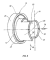
- the half wear bushing 12 shown in FIG. 3 is exactly symmetrical to the vertical center axis 31 of the lock.
- the two parts are butted against one another in the area of the plane surface 52 and connected to one another in a form-fitting manner.
- Such a positive connection is shown for example in Figure 3.
- 52 plug holes 33 are arranged in the plane surfaces, in each of which a connecting pin 34 engages.
- the connecting pin protrudes from the respective flat surface 52 and protrudes into the opposite plug hole 33 of the opposite, half-sided wear bushing 12, so that the two parts form a uniform, form-fittingly connected part.
- FIG. 2 shows that this elastomer casing 26 runs all around and is cut out only in the area of the inlet funnel 3 and the outlet funnel 51.
- the elastomer jacket has exactly the shape that the lateral sleeve jackets 28 of the wear bushing 12 have.
- end faces of the elastomer jacket which protrude into the area of the inlet funnel 3 and the outlet funnel 51, are appropriately reinforced.
- Such reinforcement can take place, for example, via a metal jacket 17 with spring steel characteristics, which metal jacket in the form of a clip part surrounds the end faces in order to protect them from inadmissible abrasion.
- the wear bushing 12 experiences a corresponding adjustment play, for example in the direction of the arrow gen 24, then the wear bush runs against the elastomeric floating layer of the elastomer casing 26 and the minimum distance 18 (Figure 1) between the upper edge 44 of the cellular wheel and the associated inner wall of the wear bushing always remains the same.
- the slide ring 8, which consists of a low-wear material, is interchangeably mounted on the support ring 7, in such a way that the slide ring 8 can be replaced without having to remove the cellular wheel 5.
- the surface of the slide ring 8 thus forms the counter-running surfaces, which define the leakage flow, in connection with the opposite inner wall of the wear bushing 12.
- the distance 18 between the surfaces mentioned can thus always be kept constant, regardless of whether the cellular wheel itself changes shape or not. If, for example, the cellular wheel 5 is adjusted in the direction of the arrow 24 according to FIG. 2, this adjustment movement is communicated to the wear bushing 12 via the bearing 10, 11 and the stub shaft 9.
- the cellular wheel 5 and the wear bushing 12 therefore make precisely synchronous movements in the adjustment direction 24, as a result of which the adjustment movement of the wear bushing 12 is absorbed by the elastomeric floating jacket 26 located on the outside.
- the adjustment play 19 (FIG. 1) serves to compensate for the necessary vertical play of the adjustment bush 12 in the area of the housing groove.
- the wear bushing 12 lies against the inside of the side cover 1.
- the housing consists of two halves divided in half, namely an upper housing shell 2 and a lower housing shell 22. This results in a parting line 20 in the horizontal plane.
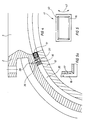
- FIG. 4 shows a further embodiment of the present invention, from which it follows that the elastomer sheath 26 is not fully present, but is replaced by an elastomer flange 16 according to the exemplary embodiment according to FIG.
- This elastomer flange 16 is therefore located only in the area of the contact surface 32 of the wear bushing 12 according to FIG. 3.
- This elastomer flange 16 thus forms a rectangular part in plan view, a rectangular part being arranged on the inlet side and a rectangular part likewise being arranged on the outlet side. Both parts are frame-shaped. The approximate shape results from FIG. 5 or FIG. 5a.
- the metal jacket 17 in the form of, for example, a chromium-nickel material, which is hung in the profile in the form of a clamp in the frame-shaped circumferential elastomer flange 16.
- the metal jacket 17 is joined at the corners via miter joints 40.
- the metal jacket 17 is clipped onto the frame-shaped plastic part (elastomer flange 16) and encompasses the inner edges of the elastomer flange, as shown in the profile in FIG.
- positioning bolts 37 are provided, which engage in assigned bores 37 on the one hand of the elastomer flange 16 and on the other hand in assigned bores 38 on the housing side. This facilitates the assembly of this frame part when the outer housing shells 2, 22 are joined together.
- the metal jacket 17 has such resilience in the radial direction of the cellular wheel, so that the required play in the arrow directions 24 is still maintained.
- the frame-shaped metal jacket 17 is fastened to the frame-shaped, circumferential elastomer flange 16 via metal clips.
- the frame part 41 As soon as the frame part 41 is produced, it must still be adapted to the spherical inner curvature of the housing shells 2, 22. This is done by rolling the entire frame part 41 in the direction of arrow 42.
- an intermediate space 35 is thus formed between the wear bushing 12 and the associated housing wall of the housing shells 2, 22.
- This space 35 can be filled with any insulating materials; it can also be filled with air or with a gas.
- This intermediate space 35 thus has a sound-insulating and temperature-insulating effect.
- FIG. 6 shows a further embodiment of the present invention, which differs from the previous embodiments in that wear protection is likewise present in the area of the inlet and outlet sides.
- a fully existing elastomer jacket 26 is shown as an example, which can just as well be replaced by the exemplary embodiment according to FIG. 4, namely by an elastomer flange 16.
- an insert 45 is also present on the inlet side (and also in an analogous manner on the outlet side), which essentially consists of an insert flange 46, e.g. consists of a chrome-nickel steel.
- This insert flange 46 thus covers the housing shells with a sensitive or aggressive medium, so that it is possible to use relatively cheap materials for the housing shells 2, 23 e.g. Cast aluminum or gray cast iron can be used and nevertheless highly wear-resistant, abrasion-resistant materials can be used in the area of the entire flow path.
- the insert flange 46 abuts a flange 48 via a welding point 47.
- a groove is screwed into the flange 48, in which an O-ring 49 is inserted.
- the entire insert part 45 is thus supported on an extension 50 which is extended in the circumferential direction on the wear bushing 12, so that the insert part 45 is held in an excellent manner.
- the web of the cellular wheel 5 shown here forms a cellular wheel chamber 43 together with other webs not shown in the drawing.
- the upper edge 44 of the cellular wheel forms the previously described minimum distance 18 in connection with the inner wall 23 of the wear bushing 12.
Landscapes
- Engineering & Computer Science (AREA)
- Mechanical Engineering (AREA)
- Sliding-Contact Bearings (AREA)
- Sealing Devices (AREA)
- Rotary Pumps (AREA)
- Investigating Or Analysing Biological Materials (AREA)
- Electromechanical Clocks (AREA)
- Component Parts Of Construction Machinery (AREA)
Claims (11)
Priority Applications (1)
| Application Number | Priority Date | Filing Date | Title |
|---|---|---|---|
| AT91109642T ATE90307T1 (de) | 1990-06-20 | 1991-06-12 | Gehaeuse fuer eine zellenradschleuse. |
Applications Claiming Priority (2)
| Application Number | Priority Date | Filing Date | Title |
|---|---|---|---|
| DE4019627 | 1990-06-20 | ||
| DE4019627A DE4019627C3 (de) | 1990-06-20 | 1990-06-20 | Gehäuse für eine Zellenradschleuse |
Publications (3)
| Publication Number | Publication Date |
|---|---|
| EP0462500A1 EP0462500A1 (fr) | 1991-12-27 |
| EP0462500B1 true EP0462500B1 (fr) | 1993-06-09 |
| EP0462500B2 EP0462500B2 (fr) | 1995-09-06 |
Family
ID=6408719
Family Applications (1)
| Application Number | Title | Priority Date | Filing Date |
|---|---|---|---|
| EP91109642A Expired - Lifetime EP0462500B2 (fr) | 1990-06-20 | 1991-06-12 | Carter pour un sas à roue cellulaire |
Country Status (3)
| Country | Link |
|---|---|
| EP (1) | EP0462500B2 (fr) |
| AT (1) | ATE90307T1 (fr) |
| DE (2) | DE4019627C3 (fr) |
Families Citing this family (9)
| Publication number | Priority date | Publication date | Assignee | Title |
|---|---|---|---|---|
| DE4244655C2 (de) * | 1992-05-06 | 2000-05-31 | Reimelt Dietrich Kg | Zellenradschleuse |
| DE4214467C2 (de) * | 1992-05-06 | 2001-07-26 | Reimelt Dietrich Kg | Zellenradschleuse |
| NO180115C (no) * | 1993-12-07 | 1997-02-19 | Ameco International As | Roterende sluseapparat utstyrt med slitebelegg og fremgangsmåte for å fremstille slitebelegget |
| DE4405828A1 (de) * | 1994-02-23 | 1995-08-24 | Krupp Polysius Ag | Zellenradschleuse |
| DE4411811C2 (de) * | 1994-04-06 | 1998-08-27 | Motan Fuller Verfahrenstechnik | Gehäuseauskleidung für eine Zellenradschleuse |
| DE19738122A1 (de) * | 1997-09-01 | 1999-03-11 | Waeschle Maschf Gmbh | Zellenradschleuse zum Dosieren von Schüttgut |
| DE19802788A1 (de) * | 1998-01-26 | 1999-08-05 | Waeschle Gmbh | Verschleißschutzhülse für Zellenradschleuse und Verfahren zur Herstellung derselben |
| DE102005048734A1 (de) * | 2005-10-12 | 2007-04-19 | Coperion Waeschle Gmbh & Co. Kg | Gehäuse für eine Zellenrad-Schleuse |
| DE102006043252B4 (de) * | 2006-09-11 | 2019-06-19 | Coperion Gmbh | Zellenradschleuse |
Family Cites Families (5)
| Publication number | Priority date | Publication date | Assignee | Title |
|---|---|---|---|---|
| GB1161204A (en) * | 1965-09-17 | 1969-08-13 | Coal Industry Patents Ltd | Pneumatic Stowing Machines. |
| DE2350033C3 (de) * | 1973-10-05 | 1982-04-01 | Jaudt, Andreas, 8901 Königsbrunn | Zellenschleuse |
| DE2732199A1 (de) * | 1977-07-16 | 1979-01-25 | Andreas Jaudt | Zellenradschleuse mit ausblasbaren radtaschen |
| GB2192164B (en) * | 1986-07-04 | 1989-12-13 | Coal Ind | Improvements in or relating to rotary valves |
| DE3722913A1 (de) * | 1987-07-10 | 1989-01-26 | Waeschle Maschf Gmbh | Gehaeuse fuer eine zellenradschleuse |
-
1990
- 1990-06-20 DE DE4019627A patent/DE4019627C3/de not_active Expired - Fee Related
-
1991
- 1991-06-12 DE DE9191109642T patent/DE59100141D1/de not_active Expired - Fee Related
- 1991-06-12 EP EP91109642A patent/EP0462500B2/fr not_active Expired - Lifetime
- 1991-06-12 AT AT91109642T patent/ATE90307T1/de not_active IP Right Cessation
Also Published As
| Publication number | Publication date |
|---|---|
| DE4019627C2 (fr) | 1992-12-24 |
| DE59100141D1 (de) | 1993-07-15 |
| EP0462500A1 (fr) | 1991-12-27 |
| ATE90307T1 (de) | 1993-06-15 |
| EP0462500B2 (fr) | 1995-09-06 |
| DE4019627A1 (de) | 1992-01-09 |
| DE4019627C3 (de) | 1998-04-23 |
Similar Documents
| Publication | Publication Date | Title |
|---|---|---|
| DE2801711C2 (de) | Radialdichtung und Verfahren zu ihrer Herstellung | |
| DE2939945C2 (fr) | ||
| DE19651112C2 (de) | Dichtungsvorrichtung für eine Motorkolbenstange | |
| DE3027133C2 (de) | Gleitringdichtung | |
| CH660407A5 (de) | Dichtring fuer kolbenstangen. | |
| EP0462500B1 (fr) | Carter pour un sas à roue cellulaire | |
| DE3213809C2 (de) | Kassettendichtung | |
| DE69309909T2 (de) | Waffendichtung mit radial komprimierbarem stützring | |
| DE2847252C3 (de) | Anordnung zur Abdichtung der Stoßstelle zwischen zwei Statorteilen einer. Turbomaschine | |
| EP1446597B1 (fr) | Bague racleuse d'huile divisee en segments | |
| EP0166855B1 (fr) | Vanne papillon pour fluides agressifs | |
| EP0462501B1 (fr) | Ecluse à rotor cellulaire avec étanchéité de fentes pour écluser des matières en vrac dans un convoyeur pneumatique | |
| DE3629410C2 (fr) | ||
| DE2853146C2 (de) | Foliengleitlager, insbesondere für Chemiepumpen | |
| EP3485185B1 (fr) | Joint etanche aux gaz | |
| DE2342069A1 (de) | Ventil mit kugelfoermigem absperrelement | |
| EP4328026B1 (fr) | Bague d'étanchéité dure à surface de glissement et dispositif d'étanchéité à glissière | |
| DE3876343T2 (de) | Magnetische dichtungseinrichtung. | |
| DE19506683C2 (de) | Kolbenstangendichtung | |
| DE2925237A1 (de) | Klappenabsperrventil | |
| DE806077C (de) | Lager fuer Wellen mit aus Streifen bestehender Lagerflaeche | |
| DE675697C (de) | Anordnung von Laufbuechsen im Zylinderkoerper von fluessigkeitsgekuehlten Brennkraftmaschinen | |
| DE8814442U1 (de) | Gleitringdichtung | |
| EP0797736B1 (fr) | Carter de pompe | |
| DE2408198C2 (de) | Zweiteiliger Kolbenring |
Legal Events
| Date | Code | Title | Description |
|---|---|---|---|
| PUAI | Public reference made under article 153(3) epc to a published international application that has entered the european phase |
Free format text: ORIGINAL CODE: 0009012 |
|
| AK | Designated contracting states |
Kind code of ref document: A1 Designated state(s): AT BE CH DE DK FR GB IT LI LU NL SE |
|
| 17P | Request for examination filed |
Effective date: 19911203 |
|
| 17Q | First examination report despatched |
Effective date: 19921117 |
|
| GRAA | (expected) grant |
Free format text: ORIGINAL CODE: 0009210 |
|
| AK | Designated contracting states |
Kind code of ref document: B1 Designated state(s): AT BE CH DE DK FR GB IT LI LU NL SE |
|
| PG25 | Lapsed in a contracting state [announced via postgrant information from national office to epo] |
Ref country code: SE Effective date: 19930609 Ref country code: DK Free format text: LAPSE BECAUSE OF NON-PAYMENT OF DUE FEES Effective date: 19930609 Ref country code: BE Effective date: 19930609 |
|
| REF | Corresponds to: |
Ref document number: 90307 Country of ref document: AT Date of ref document: 19930615 Kind code of ref document: T |
|
| PG25 | Lapsed in a contracting state [announced via postgrant information from national office to epo] |
Ref country code: AT Effective date: 19930612 |
|
| PG25 | Lapsed in a contracting state [announced via postgrant information from national office to epo] |
Ref country code: LU Free format text: LAPSE BECAUSE OF NON-PAYMENT OF DUE FEES Effective date: 19930630 |
|
| PLBI | Opposition filed |
Free format text: ORIGINAL CODE: 0009260 |
|
| REF | Corresponds to: |
Ref document number: 59100141 Country of ref document: DE Date of ref document: 19930715 |
|
| ITF | It: translation for a ep patent filed | ||
| 26 | Opposition filed |
Opponent name: BUEHLER AG Effective date: 19930708 |
|
| GBT | Gb: translation of ep patent filed (gb section 77(6)(a)/1977) |
Effective date: 19930914 |
|
| ET | Fr: translation filed | ||
| NLR1 | Nl: opposition has been filed with the epo |
Opponent name: BUHLER AG. |
|
| PUAH | Patent maintained in amended form |
Free format text: ORIGINAL CODE: 0009272 |
|
| STAA | Information on the status of an ep patent application or granted ep patent |
Free format text: STATUS: PATENT MAINTAINED AS AMENDED |
|
| ITF | It: translation for a ep patent filed | ||
| 27A | Patent maintained in amended form |
Effective date: 19950906 |
|
| AK | Designated contracting states |
Kind code of ref document: B2 Designated state(s): AT BE CH DE DK FR GB IT LI LU NL SE |
|
| REG | Reference to a national code |
Ref country code: CH Ref legal event code: AEN |
|
| ET3 | Fr: translation filed ** decision concerning opposition | ||
| NLR2 | Nl: decision of opposition | ||
| GBTA | Gb: translation of amended ep patent filed (gb section 77(6)(b)/1977) |
Effective date: 19951025 |
|
| NLR3 | Nl: receipt of modified translations in the netherlands language after an opposition procedure | ||
| NLT1 | Nl: modifications of names registered in virtue of documents presented to the patent office pursuant to art. 16 a, paragraph 1 |
Owner name: MOTAN-FUELLER VERFAHRENSTECHNIK GMBH |
|
| PGFP | Annual fee paid to national office [announced via postgrant information from national office to epo] |
Ref country code: DE Payment date: 19970508 Year of fee payment: 7 |
|
| PGFP | Annual fee paid to national office [announced via postgrant information from national office to epo] |
Ref country code: GB Payment date: 19970605 Year of fee payment: 7 |
|
| PGFP | Annual fee paid to national office [announced via postgrant information from national office to epo] |
Ref country code: FR Payment date: 19970625 Year of fee payment: 7 Ref country code: CH Payment date: 19970625 Year of fee payment: 7 |
|
| PGFP | Annual fee paid to national office [announced via postgrant information from national office to epo] |
Ref country code: NL Payment date: 19970630 Year of fee payment: 7 |
|
| PG25 | Lapsed in a contracting state [announced via postgrant information from national office to epo] |
Ref country code: GB Free format text: LAPSE BECAUSE OF NON-PAYMENT OF DUE FEES Effective date: 19980612 |
|
| PG25 | Lapsed in a contracting state [announced via postgrant information from national office to epo] |
Ref country code: LI Free format text: LAPSE BECAUSE OF NON-PAYMENT OF DUE FEES Effective date: 19980630 Ref country code: CH Free format text: LAPSE BECAUSE OF NON-PAYMENT OF DUE FEES Effective date: 19980630 |
|
| PG25 | Lapsed in a contracting state [announced via postgrant information from national office to epo] |
Ref country code: NL Free format text: LAPSE BECAUSE OF NON-PAYMENT OF DUE FEES Effective date: 19990101 |
|
| GBPC | Gb: european patent ceased through non-payment of renewal fee |
Effective date: 19980612 |
|
| REG | Reference to a national code |
Ref country code: CH Ref legal event code: PL |
|
| PG25 | Lapsed in a contracting state [announced via postgrant information from national office to epo] |
Ref country code: FR Free format text: LAPSE BECAUSE OF NON-PAYMENT OF DUE FEES Effective date: 19990226 |
|
| NLV4 | Nl: lapsed or anulled due to non-payment of the annual fee |
Effective date: 19990101 |
|
| PG25 | Lapsed in a contracting state [announced via postgrant information from national office to epo] |
Ref country code: DE Free format text: LAPSE BECAUSE OF NON-PAYMENT OF DUE FEES Effective date: 19990401 |
|
| REG | Reference to a national code |
Ref country code: FR Ref legal event code: ST |
|
| PG25 | Lapsed in a contracting state [announced via postgrant information from national office to epo] |
Ref country code: IT Free format text: LAPSE BECAUSE OF NON-PAYMENT OF DUE FEES;WARNING: LAPSES OF ITALIAN PATENTS WITH EFFECTIVE DATE BEFORE 2007 MAY HAVE OCCURRED AT ANY TIME BEFORE 2007. THE CORRECT EFFECTIVE DATE MAY BE DIFFERENT FROM THE ONE RECORDED. Effective date: 20050612 |