EP0462570B1 - Magnetischer Aufzeichnungsträger - Google Patents
Magnetischer Aufzeichnungsträger Download PDFInfo
- Publication number
- EP0462570B1 EP0462570B1 EP19910109982 EP91109982A EP0462570B1 EP 0462570 B1 EP0462570 B1 EP 0462570B1 EP 19910109982 EP19910109982 EP 19910109982 EP 91109982 A EP91109982 A EP 91109982A EP 0462570 B1 EP0462570 B1 EP 0462570B1
- Authority
- EP
- European Patent Office
- Prior art keywords
- magnetic
- spherical particles
- recording medium
- magnetic recording
- accordance
- Prior art date
- Legal status (The legal status is an assumption and is not a legal conclusion. Google has not performed a legal analysis and makes no representation as to the accuracy of the status listed.)
- Expired - Lifetime
Links
Images
Classifications
-
- G—PHYSICS
- G11—INFORMATION STORAGE
- G11B—INFORMATION STORAGE BASED ON RELATIVE MOVEMENT BETWEEN RECORD CARRIER AND TRANSDUCER
- G11B5/00—Recording by magnetisation or demagnetisation of a record carrier; Reproducing by magnetic means; Record carriers therefor
- G11B5/62—Record carriers characterised by the selection of the material
- G11B5/68—Record carriers characterised by the selection of the material comprising one or more layers of magnetisable material homogeneously mixed with a bonding agent
-
- G—PHYSICS
- G11—INFORMATION STORAGE
- G11B—INFORMATION STORAGE BASED ON RELATIVE MOVEMENT BETWEEN RECORD CARRIER AND TRANSDUCER
- G11B5/00—Recording by magnetisation or demagnetisation of a record carrier; Reproducing by magnetic means; Record carriers therefor
- G11B5/62—Record carriers characterised by the selection of the material
- G11B5/68—Record carriers characterised by the selection of the material comprising one or more layers of magnetisable material homogeneously mixed with a bonding agent
- G11B5/70—Record carriers characterised by the selection of the material comprising one or more layers of magnetisable material homogeneously mixed with a bonding agent on a base layer
-
- G—PHYSICS
- G11—INFORMATION STORAGE
- G11B—INFORMATION STORAGE BASED ON RELATIVE MOVEMENT BETWEEN RECORD CARRIER AND TRANSDUCER
- G11B5/00—Recording by magnetisation or demagnetisation of a record carrier; Reproducing by magnetic means; Record carriers therefor
- G11B5/62—Record carriers characterised by the selection of the material
- G11B5/68—Record carriers characterised by the selection of the material comprising one or more layers of magnetisable material homogeneously mixed with a bonding agent
- G11B5/70—Record carriers characterised by the selection of the material comprising one or more layers of magnetisable material homogeneously mixed with a bonding agent on a base layer
- G11B5/708—Record carriers characterised by the selection of the material comprising one or more layers of magnetisable material homogeneously mixed with a bonding agent on a base layer characterised by addition of non-magnetic particles to the layer
-
- G—PHYSICS
- G11—INFORMATION STORAGE
- G11B—INFORMATION STORAGE BASED ON RELATIVE MOVEMENT BETWEEN RECORD CARRIER AND TRANSDUCER
- G11B5/00—Recording by magnetisation or demagnetisation of a record carrier; Reproducing by magnetic means; Record carriers therefor
- G11B5/62—Record carriers characterised by the selection of the material
- G11B5/68—Record carriers characterised by the selection of the material comprising one or more layers of magnetisable material homogeneously mixed with a bonding agent
- G11B5/70—Record carriers characterised by the selection of the material comprising one or more layers of magnetisable material homogeneously mixed with a bonding agent on a base layer
- G11B5/716—Record carriers characterised by the selection of the material comprising one or more layers of magnetisable material homogeneously mixed with a bonding agent on a base layer characterised by two or more magnetic layers
-
- Y—GENERAL TAGGING OF NEW TECHNOLOGICAL DEVELOPMENTS; GENERAL TAGGING OF CROSS-SECTIONAL TECHNOLOGIES SPANNING OVER SEVERAL SECTIONS OF THE IPC; TECHNICAL SUBJECTS COVERED BY FORMER USPC CROSS-REFERENCE ART COLLECTIONS [XRACs] AND DIGESTS
- Y10—TECHNICAL SUBJECTS COVERED BY FORMER USPC
- Y10S—TECHNICAL SUBJECTS COVERED BY FORMER USPC CROSS-REFERENCE ART COLLECTIONS [XRACs] AND DIGESTS
- Y10S428/00—Stock material or miscellaneous articles
- Y10S428/90—Magnetic feature
-
- Y—GENERAL TAGGING OF NEW TECHNOLOGICAL DEVELOPMENTS; GENERAL TAGGING OF CROSS-SECTIONAL TECHNOLOGIES SPANNING OVER SEVERAL SECTIONS OF THE IPC; TECHNICAL SUBJECTS COVERED BY FORMER USPC CROSS-REFERENCE ART COLLECTIONS [XRACs] AND DIGESTS
- Y10—TECHNICAL SUBJECTS COVERED BY FORMER USPC
- Y10T—TECHNICAL SUBJECTS COVERED BY FORMER US CLASSIFICATION
- Y10T428/00—Stock material or miscellaneous articles
- Y10T428/25—Web or sheet containing structurally defined element or component and including a second component containing structurally defined particles
-
- Y—GENERAL TAGGING OF NEW TECHNOLOGICAL DEVELOPMENTS; GENERAL TAGGING OF CROSS-SECTIONAL TECHNOLOGIES SPANNING OVER SEVERAL SECTIONS OF THE IPC; TECHNICAL SUBJECTS COVERED BY FORMER USPC CROSS-REFERENCE ART COLLECTIONS [XRACs] AND DIGESTS
- Y10—TECHNICAL SUBJECTS COVERED BY FORMER USPC
- Y10T—TECHNICAL SUBJECTS COVERED BY FORMER US CLASSIFICATION
- Y10T428/00—Stock material or miscellaneous articles
- Y10T428/25—Web or sheet containing structurally defined element or component and including a second component containing structurally defined particles
- Y10T428/256—Heavy metal or aluminum or compound thereof
-
- Y—GENERAL TAGGING OF NEW TECHNOLOGICAL DEVELOPMENTS; GENERAL TAGGING OF CROSS-SECTIONAL TECHNOLOGIES SPANNING OVER SEVERAL SECTIONS OF THE IPC; TECHNICAL SUBJECTS COVERED BY FORMER USPC CROSS-REFERENCE ART COLLECTIONS [XRACs] AND DIGESTS
- Y10—TECHNICAL SUBJECTS COVERED BY FORMER USPC
- Y10T—TECHNICAL SUBJECTS COVERED BY FORMER US CLASSIFICATION
- Y10T428/00—Stock material or miscellaneous articles
- Y10T428/25—Web or sheet containing structurally defined element or component and including a second component containing structurally defined particles
- Y10T428/256—Heavy metal or aluminum or compound thereof
- Y10T428/257—Iron oxide or aluminum oxide
-
- Y—GENERAL TAGGING OF NEW TECHNOLOGICAL DEVELOPMENTS; GENERAL TAGGING OF CROSS-SECTIONAL TECHNOLOGIES SPANNING OVER SEVERAL SECTIONS OF THE IPC; TECHNICAL SUBJECTS COVERED BY FORMER USPC CROSS-REFERENCE ART COLLECTIONS [XRACs] AND DIGESTS
- Y10—TECHNICAL SUBJECTS COVERED BY FORMER USPC
- Y10T—TECHNICAL SUBJECTS COVERED BY FORMER US CLASSIFICATION
- Y10T428/00—Stock material or miscellaneous articles
- Y10T428/25—Web or sheet containing structurally defined element or component and including a second component containing structurally defined particles
- Y10T428/259—Silicic material
-
- Y—GENERAL TAGGING OF NEW TECHNOLOGICAL DEVELOPMENTS; GENERAL TAGGING OF CROSS-SECTIONAL TECHNOLOGIES SPANNING OVER SEVERAL SECTIONS OF THE IPC; TECHNICAL SUBJECTS COVERED BY FORMER USPC CROSS-REFERENCE ART COLLECTIONS [XRACs] AND DIGESTS
- Y10—TECHNICAL SUBJECTS COVERED BY FORMER USPC
- Y10T—TECHNICAL SUBJECTS COVERED BY FORMER US CLASSIFICATION
- Y10T428/00—Stock material or miscellaneous articles
- Y10T428/26—Web or sheet containing structurally defined element or component, the element or component having a specified physical dimension
- Y10T428/263—Coating layer not in excess of 5 mils thick or equivalent
- Y10T428/264—Up to 3 mils
- Y10T428/265—1 mil or less
-
- Y—GENERAL TAGGING OF NEW TECHNOLOGICAL DEVELOPMENTS; GENERAL TAGGING OF CROSS-SECTIONAL TECHNOLOGIES SPANNING OVER SEVERAL SECTIONS OF THE IPC; TECHNICAL SUBJECTS COVERED BY FORMER USPC CROSS-REFERENCE ART COLLECTIONS [XRACs] AND DIGESTS
- Y10—TECHNICAL SUBJECTS COVERED BY FORMER USPC
- Y10T—TECHNICAL SUBJECTS COVERED BY FORMER US CLASSIFICATION
- Y10T428/00—Stock material or miscellaneous articles
- Y10T428/31504—Composite [nonstructural laminate]
- Y10T428/31652—Of asbestos
- Y10T428/31663—As siloxane, silicone or silane
Definitions
- the present invention relates to a coated type magnetic recording medium (e.g. a magnetic tape and a flexible disk) for the use in an audio apparatus, a video apparatus, a computer and the like.
- a coated type magnetic recording medium e.g. a magnetic tape and a flexible disk
- a video apparatus for realizing a high quality picture, a long-time recording and a small size of the recording medium, and an audio apparatus for utilizing a digital signal have been developed.
- One of the most important devices for these apparatus is a magnetic recording medium having high recording density.
- said magnetic recording medium having high recording density in order to reduce the spacing loss during recording in the short wave length region, the surface roughness of the respective magnetic film is made very small.
- the coefficient of friction of the same becomes large, and hence the runability is deteriorated, thereby causing undesirable jitter.
- various lubricants in a group such as the group consisting of higher fatty acids, higher fatty acid esters or fluorines have been used.
- the powder sticks to the magnetic head, whereby the durability is deteriorated and the dropout is increased, since the lubricant rises to the surface of the magnetic film.
- the coefficient of friction is adjusted by the lubricant, an undesirable temperature dependency of the coefficient of friction is caused, since the lubricant has different features under different temperatures.
- EP-A 0 066 039 discloses a magnetic recording medium including a substrate carrying a coating of magnetic particles and non-magnetic load-bearing spherical particles dispersed in a binder, which said spherical particles protrude above the surface of the magnetic coating by not more than 1/5th of the thickness of said coating.
- the present invention is intended to solve the above-mentioned problems, and the purpose of the present invention is to provide a coated type magnetic recording medium having improved electromagnetic transducing characteristics and running durability.
- a magnetic recording medium comprising:
- the thickness of the surface magnetic layer depends on the wave length of recording. That is, when a usual wave length in the range of from 0.7 ⁇ m to 1.0 ⁇ m is used, a most suitable thickness of the surface magnetic layer is about 0.5 ⁇ m ⁇ 0.1 ⁇ m. Furthermore, when a short wave length in the range of from 0.3 ⁇ m to 0.6 ⁇ m is used, a most suitable thickness of the surface magnetic layer is about 0.3 ⁇ m ⁇ 0.1 ⁇ m. When the above-mentioned spherical particles are added to the surface magnetic layer of the magnetic film, since the surface magnetic layer is relatively thin (usually from 0.1 ⁇ m to 1 ⁇ m), numerous studs are formed on the surface of the surface magnetic layer of the magnetic film.
- the thick magnetic layer requires, that the spherical particles have a large diameter, or the presence of a large amount of spherical particles.
- the use of spherical particles having a large diameter or the presence of a large amount of the spherical particles in each case results in an undesirable drop-out and/or noise during the recording/reproducing. Therefore it is not desirable to use a surface magnetic layer having a thickness of more than 2 ⁇ m.
- the present invention in a magnetic film having a multilayer structure, and it is more preferable that the surface magnetic layer of the magnetic film has a thickness in the range of from 0.1 ⁇ m to 0.6 ⁇ m.
- the magnetic film consists of only one magnetic layer which has a thickness of less than 1 ⁇ m, the above-mentioned effect of the present invention is sufficient, in order to provide for the magnetic recording medium an improved electromagnetic transducing characteristic and improved running durability.
- the coefficient of friction of the magnetic film is determined by these spherical particles.
- the surface of the above-mentioned spherical particles has a good sliding characteristic, since the surface of them operates as a touching face. And furthermore, it is important to prevent an undesirable omission of the spherical particles by means of strengthening a binding power between the spherical particles and the binder resin(s). Furthermore, a surface treatment of these spherical particles becomes an effective way.
- the surface treatment agent used in the present invention can be chosen properly from the group consisting of fatty acids having at least 12 carbon atoms, for instance a lauric acid, a myristic acid, a palmitic acid, a stearic acid, an oleic acid, a behenic acid and the like only, in order to achieve the required lubricity of the spherical particles. Even in the case, when one of these acids is used without an additive in the form of a coupling agent, a sufficient effect is obtained. However, it is preferable to use a combination consisting of the acid and a coupling agent, having the effect of an increasing of the binding power between the spherical particles and the binder resins.
- Coupling agents for this combined use include: silane group coupling agents, for instance p -[N - (2 - aminoethyl) aminomethyl] phenethyltrimethoxysilane; N - (2 - aminoethyl) - 3 - aminopropylmethyldimetoxysilane; N - (2 - aminoethyl) - 3 - aminopropyltrimethoxysilane; 1 - (3 - aminopropyl) - 1, 1, 3, 3, 3 - pentamethyldisiloxane; 3 - aminopropyltriethoxysilane; 3 - aminopropyltris (trimethylsiloxy) silane; ⁇ -(2 - aminoethyl) aminopropyltrimethoxysilane; ⁇ - (2-aminoethyl) aminopropylmethyldimethoxysilane; ⁇ -glycidoxypropyltrimethoxysilane; ⁇ - mercap
- a slight amount of the spherical particles is added to the surface magnetic layer of the magnetic film, in order to obtain both a small surface roughness and a low coefficient of friction. Furthermore, additionally the surface treatment can be carried out in order to prevent an omission of the spherical particles and to achieve a good lubricity of the same; and furthermore a more stable runability during many repetitions of the running is obtainable. As a consequence of these features, a magnetic recording medium having an improved electromagnetic transducing characteristic and an improved running durability is obtained.
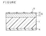
- the attached figure is a cross-sectional view of a video tape sample of Experiment 1 according to an embodiment of the present invention.
- FIG. 1 is a schematic representation for the purpose of the illustration and does not necessarily depict the actual, relative size or location of the elements as shown.
- the attached figure is a cross-sectional view of a coated type magnetic recording medium of the present invention.
- an underneath magnetic layer 2 is formed on a non-magnetic base film 1
- a surface magnetic layer 3 is formed on the underneath magnetic layer 2
- a back coat layer 4 is formed on the side, which is opposite to the side of the surface magnetic layer 3, of the base film 1.
- Spherical particles (5) included in the surface magnetic layer 3 form a plenty of studs.
- a magnetic film 6 according to the invention consists of the surface magnetic layer 3 and the underneath magnetic layer 2. Therefore it is clear, that the magnetic film 6 has the structure of a multilayer.
- a magnetic coating material hereinafter referred to as [SM] for the surface magnetic layer 3 was prepared by the following steps.
- the magnetic powder was selected from the following material as shown in Table 1.
- Spherical particles can be chosen from: spherical particles of silicon dioxide and thermal black, exclusive of alumina particles.
- the kind of spherical particles was selected from the following materials as shown in Table 2.
- thermal black particles An experiment on the base of the thermal black particles is "ASAHI THERMAL" (trade name) (having a mean diameter of 0.15 ⁇ m, whereby the range of the diameters is from 0.05 ⁇ m to 0.2 ⁇ m),which particles are supplied by ASAHI CARBON CO., LTD. JAPAN, or alternatively is “SEVACARB MT” (trade name) (having a mean diameter of 0.67 ⁇ m, whereby the range of the diameters is from 0.10 ⁇ m to 1.5 ⁇ m), supplied by Columbian Chemical Company U.S.A.
- the particle size distribution (scattering) of these thermal black particles is broader than the particle size distribution of the above-mentioned spherical particles consisting of silicon dioxide.
- SM magnetic coating material
- the diameter of the spherical particles used in the surface magnetic layer was changed, in order to prepare the respective samples and comparison samples.
- the samples 1-1, 1-2, 1-3 and 1-4 and the Comparison samples 1-1, 1-2 and 1-3 were prepared in this Experiment 1.
- Video-tape samples of the Sample 1-1 were prepared by the following procedure:
- Video-tape samples on the base of these Samples 1-2, 1-3 and 1-4 were prepared by the same procedure as described above referring to the Sample 1-1, but with the exception, that the diameter of the spherical particles used in the Step(c) was varied as follows:
- Video-tape samples on the base of this Comparison sample 1-1 were prepared by the same procedure as described above referring to the Sample 1-1, but with the exception, that no spherical particles were used in the Step(c).
- Video-tape samples on the base of this Comparison sample 1-2 were prepared by the same procedure as described above referring to the Sample 1-2, but with the exception of the omission of the Steps(a) and (b) and therefore the omission of the forming of the underneath magnetic layer 2. Furthermore, in the step(d) a 3.5 ⁇ m thick surface magnetic layer 3 was formed. Therefore, regarding the Comparison sample 1-2, the magnetic film 6 has an exceedingly thick surface magnetic layer 3.
- Video-tape samples on the base of this Comparison sample 1-3 were prepared by the same procedure as described above referring to the Comparison sample 1-2, but with the exception, that in the Step(c) the spherical particles No.3 as shown in Table 2 were used. Therefore, regarding the Comparison sample 1-3, the magnetic film 6 also has an exceedingly thick surface magnetic layer 3.
- the surface roughness of the magnetic film was measured by a non-contact type three dimensional surface roughness meter "TOPO-3D" manufactured by WYKO CO., LTD. U.S.A.
- the tape sample was wound on and around a post of 3mm ⁇ made of stainless steel at a winding angle of 180° ; the tension at the winding-in side of the post was 20.0g; and the sliding speed was 5cm/sec.
- the coefficient of friction was obtained by a measured tension at the feeding-out side of the post and the tension at the winding-in side.
- the coefficient of friction was measured after the repeating of 200 times of the above-mentioned round-trip running under the conditions of 20 gr tension at the winding-in side and at room temperature.
- the Carrier-to-noise ratio (hereinafter it is abbreviated to C/N ratio) is considered to be influenced by the surface roughness of the magnetic film, the C/N ratio at 7 MHz ⁇ 1 MHz was examined by using a VHS system VTR type "NV-FS900" manufactured by Matsushita Electric Industrial Co., Ltd. JAPAN. 7 MHz correspond to a usual wave length (i.e. 0.82 ⁇ m) as used for the recording.
- the C/N ratio was expressed in terms of a relative value referring to the C/N ratio of a tape obtained in the Comparison sample 1-1, which was assumed to be 0 dB.
- Table 3 shows the results of these evaluation tests corresponding to the respective sample tapes.
- the Sample 1-1 wherein the spherical particles have a diameter of 0.2 ⁇ m, which is less than only a half of the thickness (i.e. 0.5 ⁇ m) of the surface magnetic layer were used, showed a relatively smaller coefficient of friction than that of the Comparison sample 1-1.
- the effect obtained on the base of the Sample 1-1 was not large.
- the Samples 1-2, 1-3 and 1-4 wherein the spherical particles according to the No.2, No.3 and No.4 were used respectively, each showed a remarkable good coefficient of friction at every environmental temperature, and furthermore also a good stability of the same.
- the respective spherical particles having a diameter of 1.0 ⁇ m, which is two times as large as the thickness (i.e. 0.5 ⁇ m) of the surface magnetic layer were used, so that the surface roughness becomes large. As a consequence, this feature induced a bad influence in respect of the C/N ratio.
- the spherical particles were used in the Comparison samples 1-2 and 1-3, they gave rise to only a small reduction of the coefficient of friction and a weak effect due to the addition of the spherical particles, since the magnetic film of the Comparison samples 1-2 and 1-3 has an excessively thick (i.e. 3.5 ⁇ m) surface magnetic layer. Regarding our experiment, the surface magnetic layer which has a thickness of less than about 1 ⁇ m showed a sufficient effect due to the addition of the spherical particles. Furthermore, the magnetic recording medium which has a thin surface magnetic layer (i.e. from 0.3 ⁇ m to 1 ⁇ m) is used as a magnetic film for a flexible disk or the like.
- the amount of the spherical particles as added to the surface magnetic layer was changed in the Step(A) of the [Preparation for a magnetic coating material for the surface magnetic layer] referring to the respective samples.
- the samples 2-1, 2-2, 2-3, 2-4 and 2-5 were formed in this Experiment 2.
- Video-tape samples on the base of these Samples 2-1, 2-2, 2-3, 2-4 and 2-5 were prepared by the same procedure as described above referring to the Sample 1-3, but with the exception that the amount of the respective spherical particles was changed as follows:
- Table 4 shows the results of the evaluation tests corresponding to the respective sample tapes, including the Sample 1-3 and the Comparison sample 1-1 of the Experiment 1.
- Video-tape samples on the base of this Sample 3-1 were prepared by the same procedure as described above referring to the Sample 1-3, but with the exception, that the spherical particles after a surface treatment (i.e. corresponding to No.6 as shown in Table 2) were used.
- the surface treatment was carried out by using 1.5 parts of isopropyltriisostearoyltitanate per 100 parts of the spherical particles.
- the isopropyltriisostearoyltitanate is one of the titanate group coupling agents.
- Video-tape samples on the base of this Sample 3-2 were prepared by the same procedure as described above referring to the Sample 3-1, but with the exception, that 0.2 parts of the "SEVACARB MT" after the same surface treatment (i.e. corresponding to No.8 as shown in Table 2) as described above referring to the Sample 3-1 were used as the spherical particles instead of the respective "SEAHOSTAR type KE-P70" (i.e. No.6 shown in Table 2).
- Video-tape samples on the base of this Sample 3-3 were prepared by the same procedure as described above referring to the Sample 3-2, but with the exception, that the "SEVACARB MT" after a different surface treatment (i.e. corresponding to No.9 as shown in Table 2) was used. As mentioned above, a different surface treatment was carried out, using both 1.0 parts of myristic acid and 0.5 parts of 3-aminopropyltriethoxysilane per 100 parts of the spherical particles.
- the myristic acid is one of the fatty acids
- the 3-aminopropyltriethoxysilane is one of the silane group coupling agents.
- Table 5 shows the results of the evaluation tests corresponding to the respective sample tapes, including the reference Sample 1-3 of the Experiment 1.
- Suitable coupling agents for the surface treatment of the present invention include: silane group coupling agents, for instance p -[N - (2-aminoethyl) aminomethyl] phenethyltrimethoxysilane; N - (2 - aminoethyl) - 3 - aminopropylmethyldimethoxysilane; N - (2 aminoethyl) - 3 - amino-propyltrimethoxysilane; 1 - (3 - aminopropyl) - 1, 1, 3, 3, 3 - pentamethyldisiloxane; 3 - aminopropyltriethoxysilane; 3 - aminopropyltris (trimethylsiloxy) silane; ⁇ -(2 - aminoethyl) aminopropyltrimethoxysilane; ⁇ - (2-aminoethyl) aminopropylmethyldimethoxysilane; ⁇ -glycidoxypropyltrimethoxysilane; ⁇
- the amount of the added surface treatment agent varies depending on the surface area of the spherical particles.
- the preferable amount of the agent is in the range of from 0.5 parts to 3 parts per 100 parts of the spherical particles.
- Experiments 1, 2 and 3 relate to a Co- ⁇ Fe 2 O 3 type magnetic recording medium, which is conventionally used in a usual wave length in order to carry out the recording.
- the present invention is further applicable to a metal particles type magnetic recording medium which is suitable for the use on the base of a short recording wave length.
- the following Experiments 4 and 5 relate to the metal particles type magnetic recording medium.
- Video-tape samples on the base of this Sample 4-1 were prepared by the same procedure as described above referring to the sample 1-1, but with the exception, that:
- Video-tape samples on the base of these Samples 4-2, 4-3, 4-4 and 4-5 were made by the same procedure as described above referring to the Sample 4-1, but with the exception, that the kind of the respective spherical particles as used in the Step(c) was as follows:
- Video-tape samples on the base of this Comparison sample 4-1 were prepared by the same procedure as described above referring to the Sample 4-1, but with the exception, that no spherical particles were used in the Step(c).
- the C/N ratio at 7.7 MHz ⁇ 1 MHz was examined by using a Hi-Band 8mm system VTR type "CCD-V900", manufactured by Sony CORPORATION JAPAN. 7.7 MHz corresponds to a short recording wave length (i.e. 0.49 ⁇ m).
- the C/N ratio at short wave length was expressed in terms of a relative value referring to the C/N ratio at short wave length of a tape obtained in the Comparison sample 4-1, which was assumed to be 0 dB. Samples and comparison samples set in 8mm video tape cassettes were used in this evaluation test of course.
- the metal particle type magnetic recording medium having a thin surface magnetic layer i.e. 0.3 ⁇ m thick surface magnetic layer
- a thin surface magnetic layer i.e. 0.3 ⁇ m thick surface magnetic layer
- the Samples 4-2 and 4-3, wherein the spherical particles having a diameter (i.e. 0.5 ⁇ m and 0.7 ⁇ m), which is larger than one and a half times of the thickness (i.e. 0.3 ⁇ m) of the surface magnetic layer were used showed a low and stable coefficient of friction.
- a reduced C/N ratio was observed as a consequence of the deteriorated surface roughness.
- the spherical particles used in the surface magnetic layer should have a diameter being in the range of from 0.5 to 1.5 times as large as the respective thickness of the surface magnetic layer as the same. And furthermore, as regards the recording on the base of a short wave length, the demand for the provision of a suitable recording/reproducing characteristic becomes more severe, and therefore the more preferable range of the diameter of the spherical particles is from 0.15 ⁇ m to 0.2 ⁇ m.
- the magnetic powder used in the underneath magnetic recording layer will be changed according to the requirements in order to achieve a desirable magnetic characteristic.
- our experiment in the case, when the magnetic powder as used in the underneath magnetic recording layer was changed, a similar result as mentioned above was obtained.
- the test in order to determine the [Running durability] was carried out on the base of the Samples 1-2, 1-3, 2-1, 2-2, 3-1, 3-3 and 4-4, and the respective Comparison samples 1-1, 1-2, and 4-1.
- the Table 7 shows the results of the test.
- Comparison samples 1-1 and 4-1 wherein no spherical particles were used, both showed a large coefficient of friction. This effect resulted in unusual running while utilizing the VTR, so that numerous undulant-shaped side edges and folds of side edges were observed.
- the Comparison sample 1-2 showed a large coefficient of friction. This coefficient resulted in an unusual running while utilizing the VTR, so that numerous undulant-shaped side edges and folds of side edges were observed.
- the Sample 2-1 wherein a small amount of the spherical particles was used, showed only a weak effect, so that some deformations in form of undulant-shaped side edges were observed.
- the material of the respective magnetic powder as used in the magnetic film had no relation with any effect according to the present invention.
Landscapes
- Paints Or Removers (AREA)
- Magnetic Record Carriers (AREA)
Claims (11)
- Ein magnetisches Aufzeichnungsmedium, umfassend:ein nichtmagnetisches Substrat (1); undeinen Magnetfilm (6), welcher eine oder mehrere Schichten enthält und sich an einer Fläche des besagten nichtmagnetischen Substrats (1) befindet,dadurch gekennzeichnet, daß
der besagte Magnetfilm (6) mindestens eine magnetische Oberflächenschicht (3) aufweist, welche ein Magnetpulver, Aluminiumoxidteilchen und kugelförmige Teilchen (5) enthält, daß diese kugelförmigen Teilchen (5) aufgrund von Unterschieden im Durchmesser der kugelförmigen Teilchen (5) und der Dicke der magnetischen Oberflächenschicht (3) noppenartige (stud) Strukturen bilden, wobei die kugelförmigen Teilchen (5) Durchmesser im Bereich des 0,5- bis 1,5-fachen der Dicke der genannten magnetischen Oberflächenschicht (3) aufweisen, und in der magnetischen Oberflächenschicht (3) in einer Menge im Bereich von 0,1 bis 1 Gewichtsteil je 100 Gewichtsteile des Magnetpulvers vorliegen, und daß die genannten kugelförmigen Teilchen (5) ausgewählt sind aus Siliciumdioxidteilchen und Thermalruß-Teilchen, aber keine Aluminiumoxidteilchen sind. - Ein magnetisches Aufzeichnungsmedium nach Anspruch 1, in welchem der genannte Magnetfilm (6) außerdem eine darunter angeordnete Magnetschicht (2) aufweist.
- Ein magnetisches Aufzeichnungsmedium nach Anspruch 1, in welchem die genannte Oberflächenschicht (3) bei einer Wellenlänge in einem vorbestimmten Bereich üblicher Wellenlänge eine Dicke im Bereich von 0,4 µm bis 0,6 µm aufweist.
- Ein magnetisches Aufzeichnungsmedium nach Anspruch 1, in welchem die genannte Oberflächenschicht (3) bei einer Wellenlänge in einem vorbestimmten Bereich kurzer Wellenlänge eine Dicke im Bereich von 0,2 µm bis 0,4 µm aufweist.
- Ein magnetisches Aufzeichnungsmedium nach Anspruch 1, in welchem die genannten kugelförmigen Teilchen (5) einen Durchmesser im Bereich von 0,15 µm bis 0,2 µm aufweisen.
- Ein magnetisches Aufzeichnungsmedium nach Anspruch 1, in welchem die genannten kugelförmigen Teilchen (5) einer Oberflächenbehandlung mit einem Gleitfähigkeit verleihenden Mittel unterzogen werden.
- Ein magnetisches Aufzeichnungsmedium nach Anspruch 6, in welchem das genannte Mittel mindestens eine Verbindung ist, ausgewählt aus der Gruppe, bestehend aus:p-[N-(2-Aminoethyl)aminoethyl] phenethyl-trimethoxysilan; N-(2-Aminoethyl)-3-aminopropylmethyldimethoxysilan; N-(2-Aminoethyl)-3-aminopropyltrimethoxysilan; 1-(3-Aminopropyl)-1,1,3,3,3-pentamethyldisiloxan; 3-Aminopropyltriethoxysilan; 3-Aminopropyltris(trimethylsiloxy)silan; γ-(2-Aminoethyl)aminopropyltrimethoxyailan; γ-(2-Aminoethyl)aminopropylmethyldimethoxysilan; γ-Glycidoxypropyltrimethoxysilan; γ-Mercaptopropyltrimethoxysilan;Isopropyltriisostearoyltitanat; Isopropyl-tris(dioctylpyrophosphat)titanat; Isopropyltri (N-aminoethylaminoethyl)titanat; Tetraoctylbis(ditridecylphosphat)titanat; Bis(dioctylpyrophosphat)oxyacettitanat;Bis(dioctylpyrophosphat)ethylentitanat; Isopropyltrioctanoyltitanat; Isopropyltridecylbenzolsulfonyltitanat; Isopropyltri(dioctylphosphat)titanat; Tetrapropyl-bis(dioctylphosphat)titanat;einer Laurinsäure, einer Myristinsäure, einer Palmitinsäure, einer Stearinsäure, einer Oleinsäure und einer Behensäure, wobei die genannten Säuren mindestens 12 Kohlenstoffatome aufweisen.
- Ein magnetisches Aufzeichnungsmedium nach Anspruch 3, in welchem die genannten kugelförmigen Teilchen (5) einer Oberflächenbehandlung mit Isopropyltriisostearoyltitanat unterzogen werden.
- Ein magnetisches Aufzeichnungsmedium nach Anspruch 3, in welchem die genannten kugelförmigen Teilchen (5) einer Oberflächenbehandlung mit einer Fettsäure mit mindestens 12 Kohlenstoffatomen und 3-Aminopropyltriethoxysilan unterzogen
- Ein magnetisches Aufzeichnungsmedium nach Anspruch 4, in welchem die genannten kugelförmigen Teilchen (5) einer Oberflächenbehandlung mit Isopropyltriisostearoyltitanat unterzogen werden.
- Ein magnetisches Aufzeichnungsmedium nach Anspruch 4, in welchem die genannten kugelförmigen Teilchen (5) einer Oberflächenbehandlung mit einer Fettsäure mit mindestens 12 Kohlenstoffatomen und 3-Aminopropyltriethoxysilan unterzogen werden.
Applications Claiming Priority (2)
| Application Number | Priority Date | Filing Date | Title |
|---|---|---|---|
| JP160534/90 | 1990-06-19 | ||
| JP2160534A JPH0449519A (ja) | 1990-06-19 | 1990-06-19 | 磁気記録媒体 |
Publications (3)
| Publication Number | Publication Date |
|---|---|
| EP0462570A2 EP0462570A2 (de) | 1991-12-27 |
| EP0462570A3 EP0462570A3 (en) | 1992-01-15 |
| EP0462570B1 true EP0462570B1 (de) | 1997-11-19 |
Family
ID=15717056
Family Applications (1)
| Application Number | Title | Priority Date | Filing Date |
|---|---|---|---|
| EP19910109982 Expired - Lifetime EP0462570B1 (de) | 1990-06-19 | 1991-06-18 | Magnetischer Aufzeichnungsträger |
Country Status (5)
| Country | Link |
|---|---|
| US (1) | US5503922A (de) |
| EP (1) | EP0462570B1 (de) |
| JP (1) | JPH0449519A (de) |
| KR (1) | KR950007134B1 (de) |
| DE (1) | DE69128215T2 (de) |
Families Citing this family (17)
| Publication number | Priority date | Publication date | Assignee | Title |
|---|---|---|---|---|
| JP2566096B2 (ja) * | 1992-04-14 | 1996-12-25 | 富士写真フイルム株式会社 | 磁気記録媒体 |
| DE4227872A1 (de) * | 1992-08-22 | 1994-02-24 | Basf Magnetics Gmbh | Magnetische Aufzeichnungsträger |
| JPH06231448A (ja) * | 1992-12-28 | 1994-08-19 | Minnesota Mining & Mfg Co <3M> | 磁気記録媒体とその製造方法 |
| JPH07272256A (ja) * | 1994-03-31 | 1995-10-20 | Tdk Corp | 磁気記録媒体 |
| US5895707A (en) * | 1995-05-31 | 1999-04-20 | Sony Corporation | Magnetic recording medium |
| JPH0935251A (ja) * | 1995-07-20 | 1997-02-07 | Fuji Photo Film Co Ltd | 磁気記録媒体 |
| JPH10334458A (ja) * | 1997-06-03 | 1998-12-18 | Fuji Photo Film Co Ltd | 透明磁気記録媒体 |
| US6296996B1 (en) | 1997-06-03 | 2001-10-02 | Fuji Photo Film Co., Ltd. | Transparent magnetic recording medium |
| JP3300266B2 (ja) * | 1997-11-06 | 2002-07-08 | 株式会社日立製作所 | 磁気ディスク装置 |
| JP2001126232A (ja) * | 1999-10-28 | 2001-05-11 | Tdk Corp | 磁気記録媒体 |
| AU2003212804A1 (en) * | 2002-06-21 | 2004-01-06 | Seagate Technology Llc | Multilayer magnetic recording media |
| US7158346B2 (en) * | 2003-12-23 | 2007-01-02 | Seagate Technology Llc | Heat assisted magnetic recording film including superparamagnetic nanoparticles dispersed in an antiferromagnetic or ferrimagnetic matrix |
| US7704614B2 (en) * | 2006-10-20 | 2010-04-27 | Seagate Technology Llc | Process for fabricating patterned magnetic recording media |
| US7816023B2 (en) * | 2007-12-21 | 2010-10-19 | Imation Corp. | Magnetic recording tape having large particles in magnetic recording layer |
| US9105294B2 (en) * | 2010-03-16 | 2015-08-11 | Sony Corporation | Composite magnetic recording media |
| US9324354B2 (en) | 2010-04-02 | 2016-04-26 | Sony Corporation | Barium ferrite magnetic storage media |
| JP6334490B2 (ja) * | 2015-09-30 | 2018-05-30 | 富士フイルム株式会社 | 磁気記録媒体、磁気信号再生装置、および磁気記録媒体の製造方法 |
Family Cites Families (10)
| Publication number | Priority date | Publication date | Assignee | Title |
|---|---|---|---|---|
| JPS5240847B2 (de) * | 1972-10-05 | 1977-10-14 | ||
| US4451532A (en) * | 1981-05-29 | 1984-05-29 | International Business Machines Corporation | Magnetic recording composition employing mono-dispersed spherical load-bearing particles |
| JPS5979431A (ja) * | 1982-10-29 | 1984-05-08 | Konishiroku Photo Ind Co Ltd | 磁気記録媒体 |
| DE3408000C2 (de) * | 1984-03-03 | 1994-05-19 | Basf Ag | Magnetische Aufzeichnungsträger |
| JPS62285228A (ja) * | 1986-06-04 | 1987-12-11 | Fujitsu Ltd | 磁気デイスクの製造方法 |
| JPH0770047B2 (ja) * | 1987-07-06 | 1995-07-31 | 富士写真フイルム株式会社 | 磁気記録媒体 |
| JP2734508B2 (ja) * | 1987-08-20 | 1998-03-30 | ソニー株式会社 | 磁気記録媒体 |
| JP2581569B2 (ja) * | 1987-10-19 | 1997-02-12 | 富士写真フイルム株式会社 | オーディオテープもしくはビデオテープ |
| JP2641051B2 (ja) * | 1987-10-19 | 1997-08-13 | 富士写真フイルム株式会社 | 磁気テープ |
| US5089317A (en) * | 1989-01-20 | 1992-02-18 | Fuji Photo Film Co, Ltd. | Magnetic recording medium |
-
1990
- 1990-06-19 JP JP2160534A patent/JPH0449519A/ja active Pending
-
1991
- 1991-06-17 KR KR1019910009959A patent/KR950007134B1/ko not_active Expired - Fee Related
- 1991-06-18 EP EP19910109982 patent/EP0462570B1/de not_active Expired - Lifetime
- 1991-06-18 DE DE69128215T patent/DE69128215T2/de not_active Expired - Fee Related
-
1994
- 1994-09-27 US US08/313,410 patent/US5503922A/en not_active Expired - Fee Related
Also Published As
| Publication number | Publication date |
|---|---|
| KR950007134B1 (ko) | 1995-06-30 |
| DE69128215D1 (de) | 1998-01-02 |
| EP0462570A3 (en) | 1992-01-15 |
| KR920001447A (ko) | 1992-01-30 |
| DE69128215T2 (de) | 1998-03-12 |
| US5503922A (en) | 1996-04-02 |
| JPH0449519A (ja) | 1992-02-18 |
| EP0462570A2 (de) | 1991-12-27 |
Similar Documents
| Publication | Publication Date | Title |
|---|---|---|
| US6207252B1 (en) | Magnetic recording medium and production method thereof | |
| US5503922A (en) | Magnetic recording medium | |
| US20100143751A1 (en) | Magnetic recording media having low broadband noise | |
| EP0451703B1 (de) | Magnetisches Aufzeichnungsmedium | |
| EP0107984A1 (de) | Magnetisches Aufzeichnungsmedium | |
| US4740419A (en) | Magnetic recording media | |
| JPH04252417A (ja) | 磁気記録媒体 | |
| JPH048855B2 (de) | ||
| US4818608A (en) | Magnetic recording medium | |
| US4687705A (en) | Magnetic recording medium | |
| US20040191570A1 (en) | Magnetic recording media having increased high density broadband signal-to-noise ratio | |
| US5830556A (en) | Magnetic recording medium | |
| JP2640151B2 (ja) | 磁気記録媒体 | |
| JP2791728B2 (ja) | 磁気記録媒体 | |
| JP2568753B2 (ja) | 磁気記録媒体 | |
| JPH10162344A (ja) | 磁気記録媒体及びその製造法 | |
| US20040191574A1 (en) | Magnetic recording media having increased skirt signal-to-noise and carrier-to-noise ratios | |
| JPH06162475A (ja) | 磁気記録媒体 | |
| US20040191573A1 (en) | Magnetic recording media exhibiting decreased tape dropout performance | |
| JP3727823B2 (ja) | 磁気記録媒体 | |
| JPH0540930A (ja) | 磁気記録媒体およびその製造方法 | |
| US20060159963A1 (en) | Magnetic recording medium having low broadband noise | |
| JPS61182630A (ja) | 磁気記録媒体の製造方法 | |
| JPH04163715A (ja) | 磁気テープ及びその製造方法 | |
| JPH0463525B2 (de) |
Legal Events
| Date | Code | Title | Description |
|---|---|---|---|
| PUAI | Public reference made under article 153(3) epc to a published international application that has entered the european phase |
Free format text: ORIGINAL CODE: 0009012 |
|
| PUAL | Search report despatched |
Free format text: ORIGINAL CODE: 0009013 |
|
| 17P | Request for examination filed |
Effective date: 19910618 |
|
| AK | Designated contracting states |
Kind code of ref document: A2 Designated state(s): DE FR GB |
|
| AK | Designated contracting states |
Kind code of ref document: A3 Designated state(s): DE FR GB |
|
| RIN1 | Information on inventor provided before grant (corrected) |
Inventor name: SAKAMOTO, KAZUNORI Inventor name: SHIMASAKI, YUKIHIRO Inventor name: KISODA, AKIRA Inventor name: MIDOU, YUJI |
|
| 17Q | First examination report despatched |
Effective date: 19940216 |
|
| GRAG | Despatch of communication of intention to grant |
Free format text: ORIGINAL CODE: EPIDOS AGRA |
|
| GRAH | Despatch of communication of intention to grant a patent |
Free format text: ORIGINAL CODE: EPIDOS IGRA |
|
| GRAH | Despatch of communication of intention to grant a patent |
Free format text: ORIGINAL CODE: EPIDOS IGRA |
|
| GRAA | (expected) grant |
Free format text: ORIGINAL CODE: 0009210 |
|
| AK | Designated contracting states |
Kind code of ref document: B1 Designated state(s): DE FR GB |
|
| REF | Corresponds to: |
Ref document number: 69128215 Country of ref document: DE Date of ref document: 19980102 |
|
| ET | Fr: translation filed | ||
| PLBE | No opposition filed within time limit |
Free format text: ORIGINAL CODE: 0009261 |
|
| STAA | Information on the status of an ep patent application or granted ep patent |
Free format text: STATUS: NO OPPOSITION FILED WITHIN TIME LIMIT |
|
| 26N | No opposition filed | ||
| REG | Reference to a national code |
Ref country code: GB Ref legal event code: IF02 |
|
| PGFP | Annual fee paid to national office [announced via postgrant information from national office to epo] |
Ref country code: DE Payment date: 20070614 Year of fee payment: 17 |
|
| PGFP | Annual fee paid to national office [announced via postgrant information from national office to epo] |
Ref country code: GB Payment date: 20070613 Year of fee payment: 17 |
|
| PGFP | Annual fee paid to national office [announced via postgrant information from national office to epo] |
Ref country code: FR Payment date: 20070608 Year of fee payment: 17 |
|
| GBPC | Gb: european patent ceased through non-payment of renewal fee |
Effective date: 20080618 |
|
| REG | Reference to a national code |
Ref country code: FR Ref legal event code: ST Effective date: 20090228 |
|
| PG25 | Lapsed in a contracting state [announced via postgrant information from national office to epo] |
Ref country code: DE Free format text: LAPSE BECAUSE OF NON-PAYMENT OF DUE FEES Effective date: 20090101 |
|
| PG25 | Lapsed in a contracting state [announced via postgrant information from national office to epo] |
Ref country code: GB Free format text: LAPSE BECAUSE OF NON-PAYMENT OF DUE FEES Effective date: 20080618 |
|
| PG25 | Lapsed in a contracting state [announced via postgrant information from national office to epo] |
Ref country code: FR Free format text: LAPSE BECAUSE OF NON-PAYMENT OF DUE FEES Effective date: 20080630 |