EP0462750A2 - Appareil d'affichage d'image de télévision par projection - Google Patents
Appareil d'affichage d'image de télévision par projection Download PDFInfo
- Publication number
- EP0462750A2 EP0462750A2 EP91305308A EP91305308A EP0462750A2 EP 0462750 A2 EP0462750 A2 EP 0462750A2 EP 91305308 A EP91305308 A EP 91305308A EP 91305308 A EP91305308 A EP 91305308A EP 0462750 A2 EP0462750 A2 EP 0462750A2
- Authority
- EP
- European Patent Office
- Prior art keywords
- lens
- light
- projection lens
- green
- projection
- Prior art date
- Legal status (The legal status is an assumption and is not a legal conclusion. Google has not performed a legal analysis and makes no representation as to the accuracy of the status listed.)
- Granted
Links
Images




Classifications
-
- H—ELECTRICITY
- H04—ELECTRIC COMMUNICATION TECHNIQUE
- H04N—PICTORIAL COMMUNICATION, e.g. TELEVISION
- H04N5/00—Details of television systems
- H04N5/74—Projection arrangements for image reproduction, e.g. using eidophor
-
- H—ELECTRICITY
- H04—ELECTRIC COMMUNICATION TECHNIQUE
- H04N—PICTORIAL COMMUNICATION, e.g. TELEVISION
- H04N9/00—Details of colour television systems
- H04N9/12—Picture reproducers
- H04N9/31—Projection devices for colour picture display, e.g. using electronic spatial light modulators [ESLM]
Definitions
- This invention relates to a projection-type television display.
- Some projection-type television displays include red, green, and blue segments which produce red, green, and blue component images projected onto a large viewing screen.
- the red, green, and blue component images are combined into a composite color image on the viewing screen.
- Each of the red, green, and blue segments has a cathode-ray tube (CRT) and an optical projection system.
- CTR cathode-ray tube
- a projected image on a viewing screen tends to be contaminated by color fringes which result from chromatic aberration of lenses.
- Japanese published unexamined patent application 62-262819 discloses an optical projection system for use with a television CRT (cathode-ray tube) display.
- Japanese patent application 62-262819 uses the fact that color fringes can be decreased as light is made monochromatic.
- the prior art optical projection system of Japanese patent application 62-262819 includes an optical filter disposed frontward or rearward of a lens assembly or between lenses to suppresses an adverse effect of chromatic aberration of the lenses.
- This optical filter is composed of a colored member or a film.
- the optical filter may be formed on a lens.
- the chromaticity point of the light emitted from green light emitting CRTs deviates from the chromaticity point of the standard television green color.
- Japanese published unexamined patent application 1-254087 discloses a projection-type television display which features a filter disposed in a green projection lens unit.
- This filter has a light-wavelength-dependent reflectivity for reflecting and cutting off unnecessary components of light emitted from a green light emitting CRT.
- the unnecessary components of the light cause the green chromaticity point to deviate from the standard point.
- the filter has high reflectivities for light of wavelengths shorter than 520 nm and longer than 570 nm, and low reflectivities for light of other wavelengths.
- the reflected light components tend to be returned to the green light emitting CRT so that the contrast at the light emitting surface of the CRT may be significantly dropped.
- even necessary components of the light are appreciably reflected by the filter so that an acceptable correction of the green chromaticity point can not be attained.
- a first aspect of this invention provides a projection-type television display comprising means for generating a red image; means for generating a green image; means for generating a blue image; a common screen; a first projection lens unit for projecting the generated red image onto the screen; a second projection lens unit for projecting the generated green image onto the screen; and a third projection lens unit for projecting the generated blue image onto the screen; wherein at least one of the first, second, and third lens units comprises a colored lens having a predetermined optical filtering effect.
- a second aspect of this invention provides a projection-type television display comprising means for emitting light representing an image, the light-emitting means including a face plate; a common screen; a projection lens unit for projecting the generated image onto the screen, the projection lens unit including a projection lens; and a housing connected to the projection lens and the face plate, wherein the housing, the projection lens, and the face plate define a chamber containing coolant for cooling the light-emitting means; wherein the projection lens comprises a colored lens having a predetermined optical filtering effect for removing unnecessary components of the light emitted from the light-emitting means.
- a third aspect of this invention provides a projection-type television display comprising means for emitting red light representing a red image, the red-lightemitting means including a first face plate; means for emitting green light representing a green image, the green-light-emitting means including a second face plate; means for emitting blue light representing a blue image; a common screen; a first projection lens unit for projecting the red image onto the screen, the first projection lens unit including a first projection lens; a second projection lens unit for projecting the green image onto the screen, the second projection lens unit including a second projection lens; a third projection lens unit for projecting the blue image onto the screen; a first housing connected to the first projection lens and the first face plate, wherein the first housing, the first projection lens, and the first face plate define a first chamber containing first coolant for cooling the red-light-emitting means; and a second housing connected to the second projection lens and the second face plate, wherein the second housing, the second projection lens, and the second face plate define a second chamber containing
- a projection-type television display includes CRTs 100R, 100G, and 100B for generating red, green, and blue component images respectively.
- CRTs 100R, 100G, and 100B After being emitted from the CRTs 100R, 100G, and 100B, beams of light which represent the red, green, and blue component images are incident to projection lens units 110R, 110G, and 110B respectively.
- the beams of light pass through the projection lens units 110R, 110G, and 110B, and are then reflected by a mirror 120 before reaching a large viewing screen 130.
- the red, green, and blue component images generated by the CRTs 100R, 100G, and 100B are projected onto the large viewing screen 130 by the operation of theprojection lens units 110R, 110G, and 110B and the mirror 120.
- the projected red, green, and blue component images are combined into a composite color image.
- the projection lens units 110R, 110G, and 110B have similar internal arrangements. Only the internal design of the red lens unit 110R will be explained in detail. It should be noted that the projection lens units 110R, 110G, and 110B are different in filtering characteristics as will be explained later.
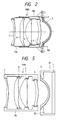
- the red lens unit 110R includes a set of successively-arranged first, second, third, fourth and fifth lenses 3, 4, 5, 6, and 7.
- the red lens unit 110R includes a cylindrical casing 150.
- the first lens 3 is held within a cylindrical holder 160 which is supported by the casing 150.
- the second, third, fourth, and fifth lenses 4, 5, 6, and 7 are held within a cylindrical holder 170 which is supported by the casing 150 and which extends into the casing 150.
- the first lens 3 follows the red CRT 100R (see Fig. 1) in the direction of the travel of the light emitted from the red CRT 100R.
- the fifth lens 7 is followed by the mirror 120 in the direction of the travel of the light emitted from the red CRT 100R.
- the first lens 3 is composed of a lens additionally having a filtering function while the second, third, fourth, and fifth lenses 4, 5, 6, and 7 are composed of non-filtering lenses.
- the first lens 3 is designed so as to have characteristics of a low pass filter in addition to intrinsic lens characteristics.
- the first lens 3 is composed of a colored plastic lens made of methacrylic resin containing coloring material. Parapet HR-11105L produced by Kuraray Company Limited can be used for the material constituting the first lens 3.
- the curve 180 denotes the wavelength spectrum of the light emitted from the red CRT 100R.
- the spectrum of the red light has a major peak extending at a wavelength of about 620 nm, and a small peak extending in a shorter-wavelength side of the major peak.
- the small peak lies in a range of wavelengths equal to or shorter than 600 nm.
- the major peak corresponds to necessary components of the red light.
- the small peak corresponds to unnecessary components of the red light which would cause the red chromaticity point to deviate from the standard point.
- the transmissivity (the reciprocal of the absorption coefficient) of the first lens 3 of the red lens unit 110R corresponds to the characteristics of a low pass filter which absorbs the unnecessary components of the red light (the small peak but which efficiently transmits the necessary components of the red light (the major peak).
- the curve 182 denotes the wavelength spectrum of the red light outputted from the first lens 3 of the red lens unit 110R. As is understood from the comparison between the curves 180 and 182, the unnecessary components of the red light (the small peak) are remarkably damped by the first lens 3 while the necessary components of the red light (the major peak) are efficiently transmitted through the first lens 3.
- a first lens 3 is composed of a lens additionally having a filtering function while second, third, fourth, and fifth lenses 4, 5, 6, and 7 are composed of non-filtering lenses.
- the first lens 3 is designed so as to have characteristics of a high pass filter in addition to intrinsic lens characteristics.
- the first lens 3 is composed of a colored plastic lens made of methacrylic resin containing coloring material. Parapet HR-14097L produced by Kuraray Company Limited can be used for the material constituting the first lens 3.
- the curve 190 denotes the wavelength spectrum of the light emitted from the green CRT 100G.
- the spectrum of the green light has a major peak extending at a wavelength of about 550 nm, and two small peaks extending in a longer-wavelength side of the major peak.
- the small peaks lie in a range of wavelengths equal to or longer than 570 nm.
- the major peak corresponds to necessary components of the green light.
- the small peaks correspond to unnecessary components of the green light which would cause the green chromaticity point to deviate from the standard point.
- the transmissivity of the first lens 3 of the green lens unit 110G corresponds to the characteristics of a high pass filter which absorbs the unnecessary components of the green light (the small peaks) but which efficiently transmits the necessary components of the green light (the major peak).
- the curve 192 denotes the wavelength spectrum of the green light outputted from the first lens 3 of the green lens unit 110G. As is understood from the comparison between the curves 190 and 192, the unnecessary components of the green light (the small peaks) are remarkably damped by the first lens 3 while the necessary components of the green light (the major peak) are efficiently transmitted through the first lens 3.
- An embodiment 2 is similar to the embodiment 1 except for the following design change.
- a first lens 3 is composed of a lens additionally having a filtering function while second, third, fourth, and fifth lenses 4, 5, 6, and 7 are composed of non-filtering lenses.
- the first lens 3 is designed so as to have characteristics of a low pass filter in addition to intrinsic lens characteristics.
- the first lens 3 is composed of a colored plastic lens made of methacrylic resin containing coloring material. Parapet HR-14092L produced by Kuraray Company Limited can be used for the material constituting the first lens 3.
- the spectrum of the green light has a major peak extending at a wavelength of about 550 nm, and a small peak extending in a shorter-wavelength side of the major peak.
- the small peak lies in a range of wavelengths equal to or shorter than 520 nm.
- the major peak corresponds to necessary components of the green light.
- the small peak corresponds to unnecessary components of the green light which would cause the green chromaticity point to deviate from the standard point.
- the transmissivity of the first lens 3 of the green lens unit 110G corresponds to the characteristics of a low pass filter which absorbs the unnecessary components of the green light (the small peak) but which efficiently transmits the necessary components of the green light (the major peak).
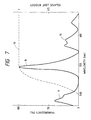
- Fig. 7 shows an example of the low-pass filtering characteristics of the first lens 3 of the green lens unit 110G.
- the spectrum of the green light has a major peak and small peaks.
- the low pass filtering characteristics of the first lens 3 of the green lens unit 110G are designed so that the major peak can be efficiently transmitted but the shorter-wavelength small peak can be adequately absorbed.
- An embodiment 3 is similar to the embodiment 1 except for the following design change.
- a first lens 3 is composed of a lens additionally having a filtering function while second, third, fourth, and fifth lenses 4, 5, 6, and 7 are composed of non-filtering lenses.
- the first lens 3 is designed so as to have characteristics of a band pass filter in addition to intrinsic lens characteristics.
- the first lens 3 is composed of a colored plastic lens made of methacrylic resin containing coloring material. Parapet 14W-016L produced by Kuraray Company Limited can be used for the material constituting the first lens 3.
- the spectrum of the green light has a major peak extending at a wavelength of about 550 nm, and three small peaks extending around the major peak. Two of the small peaks lie in a range of wavelengths equal to or longer than 570 nm, and the other small peak lies in a range of wavelengths equal to or shorter than 520 nm.
- the major peak corresponds to necessary components of the green light.
- the small peaks correspond to unnecessary components of the green light which would cause the green chromaticity point to deviate from the standard point.
- the transmissivity of the first lens 3 of the green lens unit 110G corresponds to the characteristics of a band pass filter which absorbs the unnecessary components of the green light (the small peaks) but which efficiently transmits the necessary components of the green light (the major peak).
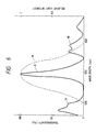
- Fig. 6 shows an example of the band-pass filtering characteristics of the first lens 3 of the green lens unit 110G.
- the spectrum of the green light has a major peak and small peaks.
- the bandpass filtering characteristics of the first lens 3 of the green lens unit 110G are designed so that the major peak can be efficiently transmitted but the small peaks can be adequately absorbed.
- An embodiment 4 is similar to the embodiment 1 except for the following additional design.
- a first lens 3 is composed of a lens additionally having a filtering function while second, third, fourth, and fifth lenses 4, 5, 6, and 7 are composed of non-filtering lenses.
- the first lens 3 is designed so as to have characteristics of a low pass filter in addition to intrinsic lens characteristics.
- the first lens 3 is composed of a colored plastic lens made of methacrylic resin containing coloring material. Parapet 13V-004L produced by Kuraray Company Limited can be used for the material constituting the first lens 3.
- the spectrum of the blue light emitted from the blue CRT 100B has a major peak extending at a wavelength of about 450 nm.
- the major peak corresponds to necessary components of the blue light.
- the blue light emitted from the blue CRT 100B also has unnecessary components of wavelengths equal to or shorter than 420 nm. The unnecessary components of the blue light would cause the blue chromaticity point to deviate from the standard point.
- the transmissivity of the first lens 3 of the blue lens unit 110B corresponds to the characteristics of a low pass filter which absorbs the unnecessary components of the blue light but which efficiently transmits the necessary components of the blue light (the major peak).
- Fig. 9 shows an example of the low-pass filtering characteristics of the first lens 3 of the blue lens unit 110B.
- the spectrum of the blue light has a major peak.
- the low-pass filtering characteristics of the first lens 3 of the blue lens unit 110B are designed so that the major peak can be efficiently transmitted.
- An embodiment 5 is similar to the embodiment 1 except for the following additional design.
- a first lens 3 is composed of a lens additionally having a filtering function while second, third, fourth, and fifth lenses 4, 5, 6, and 7 are composed of non-filtering lenses.
- the first lens 3 is designed so as to have characteristics of a band pass filter in addition to intrinsic lens characteristics.
- the first lens 3 is composed of a colored plastic lens made of methacrylic resin containing coloring material. Parapet 18W-013L produced by Kuraray Company Limited can be used for the material constituting the first lens 3.
- the spectrum of the blue light emitted from the blue CRT 100B has a major peak extending at a wavelength of about 450 nm.
- the major peak corresponds to necessary components of the blue light.
- the blue light emitted from the blue CRT 100B also has unnecessary components of wavelengths equal to or shorter than 420 nm, and unnecessary components of wavelengths equal to or longer than 500 nm.
- the unnecessary components of the blue light would cause the blue chromaticity point to deviate from the standard point.
- the transmissivity of the first lens 3 of the blue lens unit 110B corresponds to the characteristics of a band pass filter which absorbs the unnecessary components of the blue light but which efficiently transmits the necessary components of the blue light (the major peak).
- Fig. 8 shows an example of the band-pass filtering characteristics of the first lens 3 of the blue lens unit 110B.
- the spectrum of the blue light has a major peak.
- the band-pass filtering characteristics of the first lens 3 of the blue lens unit 110B are designed so that the major peak can be efficiently transmitted.
- An embodiment 6 is similar to the embodiment 4 except for the following design change.
- a green lens unit 110G is designed as in the embodiment 2.
- An embodiment 7 is similar to the embodiment 5 except for the following design change.
- a green lens unit 110G is designed as in the embodiment 2.
- An embodiment 8 is similar to the embodiment 4 except for the following design change.
- a green lens unit 110G is designed as in the embodiment 3.
- An embodiment 9 is similar to the embodiment 5 except for the following design change.
- a green lens unit 110G is designed as in the embodiment 3.
- An embodiment 10 is similar to the embodiment 1 except for the following design changes. ,
- a fifth lens 7 is composed of a lens additionally having a filtering function while first, second, third, and fourth lenses 3, 4, 5, and 6 are composed of non-filtering lenses.
- a fifth lens 7 is composed of a lens additionally having a filtering function while first, second, third, and fourth lenses 3, 4, 5, and 6 are composed of non-filtering lenses.
- the embodiment 10 may be modified as one of the embodiments 2-9.
- An embodiment 11 is similar to the embodiment 1 except for the following additional design.
- a fifth lens 7 is composed of a lens additionally having a filtering function. Specifically, the fifth lens 7 is designed so as to have characteristics of a low pass filter in addition to intrinsic lens characteristics as the first lens 3 of the embodiment 2.
- Fig. 5 shows an embodiment 12 which is similar to the embodiment 1 except for the following design changes.
- a red lens unit 110R includes a set of successively-arranged first, second, third, fourth and fifth lenses 3, 4, 5, 6, and 7.
- the first lens 3 is fitted into an end of a cylindrical housing 31.
- a glass face plate 1 of a red CRT 100R (see Fig. 1) is fitted into the other end of the cylindrical housing 31.
- the first lens 3, the cylindrical housing 31, and the CRT face plate 1 define a chamber 33 containing coolant for cooling the light-emitting part of the red CRT 100R.
- the red lens unit 110R includes a cylindrical holder 34 within which the second, third, fourth, and fifth lenses 4, 5, 6, and 7 are held.
- the internal arrangement of a green lens unit 110G is similar to the internal arrangement of the red lens unit 110R of Fig. 5.
- the embodiment 12 may be modified as one of the embodiments 2-11.
Landscapes
- Engineering & Computer Science (AREA)
- Multimedia (AREA)
- Signal Processing (AREA)
- Video Image Reproduction Devices For Color Tv Systems (AREA)
- Projection Apparatus (AREA)
- Lenses (AREA)
- Optical Filters (AREA)
Applications Claiming Priority (2)
| Application Number | Priority Date | Filing Date | Title |
|---|---|---|---|
| JP2160527A JPH0451107A (ja) | 1990-06-19 | 1990-06-19 | 投写型テレビジョン装置 |
| JP160527/90 | 1990-06-19 |
Publications (3)
| Publication Number | Publication Date |
|---|---|
| EP0462750A2 true EP0462750A2 (fr) | 1991-12-27 |
| EP0462750A3 EP0462750A3 (en) | 1992-04-22 |
| EP0462750B1 EP0462750B1 (fr) | 1997-09-10 |
Family
ID=15716894
Family Applications (1)
| Application Number | Title | Priority Date | Filing Date |
|---|---|---|---|
| EP91305308A Expired - Lifetime EP0462750B1 (fr) | 1990-06-19 | 1991-06-12 | Appareil d'affichage d'image de télévision par projection |
Country Status (7)
| Country | Link |
|---|---|
| EP (1) | EP0462750B1 (fr) |
| JP (1) | JPH0451107A (fr) |
| KR (1) | KR950010734B1 (fr) |
| AU (1) | AU627659B2 (fr) |
| CA (1) | CA2044904A1 (fr) |
| DE (1) | DE69127589T2 (fr) |
| MY (1) | MY109670A (fr) |
Families Citing this family (2)
| Publication number | Priority date | Publication date | Assignee | Title |
|---|---|---|---|---|
| KR100717270B1 (ko) * | 2005-06-28 | 2007-05-15 | 삼성전자주식회사 | 프로젝션 렌즈유닛의 제조방법 |
| JP5570171B2 (ja) * | 2009-10-06 | 2014-08-13 | キヤノン株式会社 | 撮像装置及び監視カメラ |
Family Cites Families (5)
| Publication number | Priority date | Publication date | Assignee | Title |
|---|---|---|---|---|
| US4753519A (en) * | 1984-09-27 | 1988-06-28 | Matsushita Electric Industrial Co., Ltd. | Optical system for projection television apparatus |
| CA1274613A (fr) * | 1986-12-24 | 1990-09-25 | Leendert Vriens | Dispositifs connexes de projection et d'affichage |
| JP2565976B2 (ja) * | 1988-04-04 | 1996-12-18 | 三菱電機株式会社 | 投写型テレビジョン装置 |
| JPH0760202B2 (ja) * | 1989-07-31 | 1995-06-28 | パイオニア株式会社 | プロジェクションテレビ用投写装置 |
| US5055922A (en) * | 1990-03-07 | 1991-10-08 | U.S. Precision Lens Incorporated | Color tv projection lens system |
-
1990
- 1990-06-19 JP JP2160527A patent/JPH0451107A/ja active Pending
-
1991
- 1991-06-12 MY MYPI91001040A patent/MY109670A/en unknown
- 1991-06-12 EP EP91305308A patent/EP0462750B1/fr not_active Expired - Lifetime
- 1991-06-12 DE DE69127589T patent/DE69127589T2/de not_active Expired - Fee Related
- 1991-06-13 AU AU78372/91A patent/AU627659B2/en not_active Ceased
- 1991-06-18 CA CA002044904A patent/CA2044904A1/fr not_active Abandoned
- 1991-06-19 KR KR1019910010167A patent/KR950010734B1/ko not_active Expired - Fee Related
Also Published As
| Publication number | Publication date |
|---|---|
| AU7837291A (en) | 1992-01-02 |
| CA2044904A1 (fr) | 1991-12-20 |
| DE69127589D1 (de) | 1997-10-16 |
| KR920001952A (ko) | 1992-01-30 |
| JPH0451107A (ja) | 1992-02-19 |
| AU627659B2 (en) | 1992-08-27 |
| EP0462750A3 (en) | 1992-04-22 |
| MY109670A (en) | 1997-04-30 |
| DE69127589T2 (de) | 1998-01-22 |
| EP0462750B1 (fr) | 1997-09-10 |
| KR950010734B1 (ko) | 1995-09-22 |
Similar Documents
| Publication | Publication Date | Title |
|---|---|---|
| EP0445513B1 (fr) | Système de lentilles de projection améliorée pour TV en couleur | |
| US4679069A (en) | Color picture projection system with a wavelength-selective reflector for filtering out undesired light from a monochrome picture display source | |
| US5168351A (en) | Short focal length video color projector employing dichroic mirror block | |
| EP0750822B1 (fr) | Combineur de faisceaux pour projecteur a affichage a cristaux liquides | |
| US4454535A (en) | Color picture projection system | |
| EP0732848B1 (fr) | Projecteur vidéo | |
| EP0405953B1 (fr) | Appareil-source de lumière pour séparer la lumière blanche en composantes de différentes couleurs | |
| US4084179A (en) | Color television camera | |
| US5805244A (en) | Liquid crystal projector using a monochromatic liquid crystal display | |
| EP0696361B1 (fr) | Systeme dichroique immerge pour projecteur video a lentille de projection unique | |
| US5559564A (en) | Cathode ray tube apparatus for projection TV system | |
| US5010396A (en) | Television projector for projection display | |
| US4987483A (en) | Projection television set | |
| EP0462750A2 (fr) | Appareil d'affichage d'image de télévision par projection | |
| US6275272B1 (en) | Projection television receiver | |
| US6115081A (en) | Projection image display apparatus | |
| JPH09146039A (ja) | 投写型表示装置 | |
| US5903089A (en) | Monochrome CRT having curved display window with reduced transmission and projection color TV incorporating same | |
| JPH0744688B2 (ja) | 投写型テレビジヨン装置 | |
| JPS59139537A (ja) | 投写型カラ−テレビジョン受像機 | |
| JPH04212141A (ja) | ビデオプロジェクタ装置 | |
| KR930002114B1 (ko) | Lcd프로젝션용 색 분리장치 | |
| JP2536634Y2 (ja) | 液晶プロジェクタ | |
| JPH0834596B2 (ja) | 投写型テレビジョン装置 | |
| JPS59112545A (ja) | 投写型ブラウン管 |
Legal Events
| Date | Code | Title | Description |
|---|---|---|---|
| PUAI | Public reference made under article 153(3) epc to a published international application that has entered the european phase |
Free format text: ORIGINAL CODE: 0009012 |
|
| 17P | Request for examination filed |
Effective date: 19910621 |
|
| AK | Designated contracting states |
Kind code of ref document: A2 Designated state(s): DE GB |
|
| PUAL | Search report despatched |
Free format text: ORIGINAL CODE: 0009013 |
|
| AK | Designated contracting states |
Kind code of ref document: A3 Designated state(s): DE GB |
|
| 17Q | First examination report despatched |
Effective date: 19940422 |
|
| GRAG | Despatch of communication of intention to grant |
Free format text: ORIGINAL CODE: EPIDOS AGRA |
|
| GRAH | Despatch of communication of intention to grant a patent |
Free format text: ORIGINAL CODE: EPIDOS IGRA |
|
| GRAH | Despatch of communication of intention to grant a patent |
Free format text: ORIGINAL CODE: EPIDOS IGRA |
|
| GRAA | (expected) grant |
Free format text: ORIGINAL CODE: 0009210 |
|
| AK | Designated contracting states |
Kind code of ref document: B1 Designated state(s): DE GB |
|
| REF | Corresponds to: |
Ref document number: 69127589 Country of ref document: DE Date of ref document: 19971016 |
|
| PLBE | No opposition filed within time limit |
Free format text: ORIGINAL CODE: 0009261 |
|
| STAA | Information on the status of an ep patent application or granted ep patent |
Free format text: STATUS: NO OPPOSITION FILED WITHIN TIME LIMIT |
|
| 26N | No opposition filed | ||
| REG | Reference to a national code |
Ref country code: GB Ref legal event code: IF02 |
|
| PGFP | Annual fee paid to national office [announced via postgrant information from national office to epo] |
Ref country code: GB Payment date: 20050608 Year of fee payment: 15 |
|
| PGFP | Annual fee paid to national office [announced via postgrant information from national office to epo] |
Ref country code: DE Payment date: 20050609 Year of fee payment: 15 |
|
| PG25 | Lapsed in a contracting state [announced via postgrant information from national office to epo] |
Ref country code: GB Free format text: LAPSE BECAUSE OF NON-PAYMENT OF DUE FEES Effective date: 20060612 |
|
| PG25 | Lapsed in a contracting state [announced via postgrant information from national office to epo] |
Ref country code: DE Free format text: LAPSE BECAUSE OF NON-PAYMENT OF DUE FEES Effective date: 20070103 |
|
| GBPC | Gb: european patent ceased through non-payment of renewal fee |
Effective date: 20060612 |