EP0462997B1 - Hydropneumatische vorrichtung zum höhenverstellen von stühlen - Google Patents
Hydropneumatische vorrichtung zum höhenverstellen von stühlen Download PDFInfo
- Publication number
- EP0462997B1 EP0462997B1 EP90903915A EP90903915A EP0462997B1 EP 0462997 B1 EP0462997 B1 EP 0462997B1 EP 90903915 A EP90903915 A EP 90903915A EP 90903915 A EP90903915 A EP 90903915A EP 0462997 B1 EP0462997 B1 EP 0462997B1
- Authority
- EP
- European Patent Office
- Prior art keywords
- oil
- chamber
- piston
- under
- seat
- Prior art date
- Legal status (The legal status is an assumption and is not a legal conclusion. Google has not performed a legal analysis and makes no representation as to the accuracy of the status listed.)
- Expired - Lifetime
Links
- 230000000694 effects Effects 0.000 claims description 6
- 239000000463 material Substances 0.000 claims description 6
- 125000004122 cyclic group Chemical group 0.000 claims description 4
- 238000007789 sealing Methods 0.000 description 4
- 230000006837 decompression Effects 0.000 description 1
- 238000007599 discharging Methods 0.000 description 1
- 238000006073 displacement reaction Methods 0.000 description 1
- 238000000605 extraction Methods 0.000 description 1
- 230000008595 infiltration Effects 0.000 description 1
- 238000001764 infiltration Methods 0.000 description 1
- 238000004519 manufacturing process Methods 0.000 description 1
- 230000010355 oscillation Effects 0.000 description 1
- 230000003068 static effect Effects 0.000 description 1
Images

Classifications
-
- A—HUMAN NECESSITIES
- A47—FURNITURE; DOMESTIC ARTICLES OR APPLIANCES; COFFEE MILLS; SPICE MILLS; SUCTION CLEANERS IN GENERAL
- A47C—CHAIRS; SOFAS; BEDS
- A47C3/00—Chairs characterised by structural features; Chairs or stools with rotatable or vertically-adjustable seats
- A47C3/20—Chairs or stools with vertically-adjustable seats
- A47C3/30—Chairs or stools with vertically-adjustable seats with vertically-acting fluid cylinder
Definitions
- the present invention has for object an adjustable oleopneumatic amortized support column, for chairs and armchairs.
- the innovation finds particular even if not exclusive application as support sprung structure regulable in height for office chairs.
- a second disclosed solution is IT-41632A/85 and WO,A1,8807828 "LIFTER srl" (in the name of same applicant , the second one being based on the first one, without claiming respective priority) that provides the realization of a similar support but wherein the second tube is slidable internally to the first rather than externally;
- the device does not present valid axial guide means as in the first solution, that involves the further damaging of said seals and an inevitable misalignment for oscillation.
- EP, A,343339 (BANSBACH, HERMANN) solution, being conceived substantially in similar way.
- EP, A,343339 discloses one additional piston means below the first piston means.
- the functional effect of the two oil chambers acting as a whole mentioned in this application is not achieved.
- Purpose of the present invention is to obviate the mentioned drawbacks.
- This solution makes possible a displacement of the oil chambers ensemble inside the first body (being, said chambers, above the compressed air chamber) and simultaneously eliminate the decompression effect and any oil leakage that easily could happen in the previous solutions.
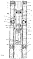
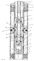
- Said valve means include an axial pull-reciprocable (axially alternately movable in reciprocation by said means of a lever command) that involves three ring seals and slides into said second body in an intermediate chamber formed by a cartridge case and counter cartridge case that involves two series of holes of different height level and in which the excursion of said draw deplaces:
- the lower air/gas chamber is notably widened improving sensitively the elastic effect without modify the external encumber.
- this column is utilizable even in absence of air or gas in the chamber, because, putting the valve means in intermediate position, the seat can be placed manually to the desired height and in that blocked point, putting said valve means in rest position.
- a chair oleopneumatic adjustable and amortized column support e comprising:
- said second body (B) is internally empty and its hollow is opened inferiorly toward said basis chamber (Z) and extends until under said intercommunication device between the two oil chambers.
- the two floating pistons (4, 6) are in O-Ring seal shape and are slidable freely both long the first body and long the second body, in this way the oil chamber (X, Y) becomes floating also and above and under this, forms two air chambers, one principal lower chamber (Z) for the amortisement and one upper chamber for interspace (Z') in the moment of the sat.
- the lower guide (3) is conveniently in plastic material.
- the structure of the entire device includes furthermore in the internal of the second body (B):
- the inserts 8, 9, 12, 10, 13, 14 are conveniently in plastic material.
- the channels for the passage of the oil through the valve system and the holes series have been calculated to consent the control of the descending speed and climbed of the seat.
Landscapes
- Chairs Characterized By Structure (AREA)
- Fluid-Damping Devices (AREA)
- Chairs For Special Purposes, Such As Reclining Chairs (AREA)
Claims (7)
- Eine verstellbare stoßgedämpfte Öl-Luft-Tragsäule für Stuhl mit:- einem ersten Hohlzylinder (A), dessen Unterseite fest mit dem Stuhlständer verbunden ist, und- einen zweiten Hohlzylinder (B) als verschiebbare obere koaxiale Stange in dem ersten, dessen oberes Ende unter dem Stuhlsitz befestigt ist;- eine koaxiale innere Steuerstange, die durch einen Hebel unter dem Sitz nach oben und unten bewegt werden kann (8) und in den ersten und zweiten Hohlzylinder ragt, verbunden mit:- einem ersten verschiebbaren Kolben (5) in dem ersten Hohlzylinder, der außen blockiert ist, um an dem zweiten Hohlzylinder (B) zu haften, und der zwei Kammern bildet, eine obere und eine untere (X-Y), die Öl enthalten, mit einem Ventil (10), das den Ölstrom aus der einen Kammer in die andere zuläßt oder verhindert, so daß durch Benutzen des genannten Hebels unter dem Sitz Höhenverstellung möglich wird; gekennzeichnet dadurch, daß:- zwei weitere Schwimmkolben zwischen dem besagten ersten (A) und zweiten (B) Hohlzylinder vorhanden sind, einer oberhalb (6) und einer unterhalb (4) des genannten ersten Kolbens (5), so daß ein Paar von Ölkammern entsteht (X-Y), die gleichzeitig gemeinsam innerhalb des ersten Hohlzylinders (A) beim Sitzen verschiebbar sind, mit stoßdämpfender Wirkung.
- Eine Stuhl-Tragsäule wie nach Anspruch 1, gekennzeichnet dadurch, daß besagtes Ventil (10) einen beidseitig ausziehbaren Kolben (10) enthält, der drei Siegelringe (10', 10'', 10''') umfaßt, die in besagtem zweiten Hohlzylinder (B) in einer Zwischenkammer verschiebbar sind, die aus einem unteren Kolbengehäuse (13) und einem oberen Kolbengehäuse (12) gebildet wird und zwei Lochreihen in verschiedener Höhe (10n', 10n'') umfaßt, und in der sich der genannte Ausziehkolben (10) wie folgt bewegt:- aus einer Stellung mit dem mittleren Siegelring zwischen den genannten beiden Lochreihen (Fig. 2), wobei er den Ölfluß aus der einen (X) in die andere Kammer (Y) unterbindet,- in eine Stellung, die im wesentlichen mit den Lochreihen zyklisch zusammenfällt (10n''), aber nicht daneben, wobei der Ölfluß geöffnet wird.
- Eine Stuhl-Tragsäule wie nach Anspruch 1, gekennzeichnet dadurch, daß besagtes Ventil (10) einen beidseitig ausziehbaren Kolben (10) enthält, der drei Siegelringe (10', 10'', 10''') umfaßt, die in besagtem zweiten Hohlzylinder (B) in einer Zwischenkammer verschiebbar sind, die aus einem unteren Kolbengehäuse (13) und einem oberen Kolbengehäuse (12) gebildet wird und zwei Lochreihen in verschiedener Höhe (10n', 10n'') umfaßt, und in der sich der genannte Ausziehkolben (10) bewegt:- aus einer Stellung mit dem mittleren Siegelring zwischen den genannten beiden Lochreihen (Fig. 2), wobei er den Ölfluß aus der einen (X) in die andere Kammer (Y) unterbindet,- in eine Stellung, die im wesentlichen mit den Lochreihen zyklisch zusammenfällt (10n''), aber nicht daneben, wobei der Ölfluß geöffnet wird,- wobei besagte Lochreihen zumindest in zyklischer Koinzidenz abgekantet sind.
- Eine Stuhl-Tragsäule wie nach Anspruch 1, gekennzeichnet dadurch, daß besagter Hohlzylinder (B) innen hohl ist und nach unten geöffnet zu der genannten Basiskammer (Z), und daß er sich bis unter besagtes Verhindungsmittel zwischen den beiden Ölkammern in besagtem zweiten Hohlzylinder erstreckt, der bis unter das genannte Ventil reicht.
- Eine Stuhl-Tragsäule wie nach Anspruch 1, gekennzeichnet dadurch, daß unten in besagtem Hohlzylinder ein untere röhrenförmige Blockiersteuerung angebracht ist (3), die:- den unteren Teil des genannten Hohlzylinders axial führt und- als unterer Stoßbegrenzer des genannten ersten Kolbens wirkt, der mit einem Schwimmkolben verbunden ist.
- Eine Stuhl-Tragsäule wie nach Anspruch 1, gekennzeichnet dadurch, daß die beiden Schwimmkolben (4, 6) die Form von Siegelringen haben und sowohl längs des ersten Hohlzylinders als auch längs des zweiten Hohlzylinders frei verschiebbar sind, so daß auch die Ölkammer (X, Y) schwimmend wird und darüber und darunter zwei Luftkammern gebildet werden, eine untere Hauptluftkammer zur Stoßdämpfung (Z) und eine obere Luftkammer als Zwischenraum (Z').
- Eine Stuhl-Tragsäule wie nach Anspruch 1, gekennzeichnet dadurch, daß die Struktur der gesamten Vorrichtung des weiteren im Innern des zweiten Hohlzylinders (B) eine untere Blockierröhre (14) aus Kunststoff umfaßt, die ein geschlossenes unteres Kolbengehäuse (13), ebenfalls aus Kunststoff, trägt, welche eine gewundene Feder (11) und oben einen Siegelring (13') enthält, damit die Druckluft nicht aus der unteren Luftkammer (Z) in die obere Ölkammer gerät, und in welcher besagtes geschlossenes unteres Kolbengehäuse (13 ) wirkt, zusammen mit einem oberen Kolbengehäuse (12) und zwei Löchern (10n'- 10n'') sowie zwei äußeren Siegelringen (12'-2'') gegen den zweiten Hohlzylinder (B), die hohe runde Löcher (Bn'-Bn'') entsprechend dem zweiten Hohlzylinder aufweisen und zwischen sie in mittlerer und oberer Lage eingefügt sind sowie ein Ausziehkolbenventil (10) enthalten.
Applications Claiming Priority (3)
| Application Number | Priority Date | Filing Date | Title |
|---|---|---|---|
| IT8983355A IT1234608B (it) | 1989-03-13 | 1989-03-13 | Colonna di supporto oleopneumatica regolabile, ammortizzata. |
| IT8335589 | 1989-03-13 | ||
| US07/768,041 US5294086A (en) | 1989-03-13 | 1991-10-01 | Adjustable oleopneumatic amortized support column, for chairs and armchairs |
Publications (2)
| Publication Number | Publication Date |
|---|---|
| EP0462997A1 EP0462997A1 (de) | 1992-01-02 |
| EP0462997B1 true EP0462997B1 (de) | 1993-09-08 |
Family
ID=26330063
Family Applications (1)
| Application Number | Title | Priority Date | Filing Date |
|---|---|---|---|
| EP90903915A Expired - Lifetime EP0462997B1 (de) | 1989-03-13 | 1990-02-23 | Hydropneumatische vorrichtung zum höhenverstellen von stühlen |
Country Status (11)
| Country | Link |
|---|---|
| US (1) | US5294086A (de) |
| EP (1) | EP0462997B1 (de) |
| CN (1) | CN1017401B (de) |
| AR (1) | AR244968A1 (de) |
| AT (1) | ATE94036T1 (de) |
| AU (1) | AU5162490A (de) |
| DE (1) | DE69003240T2 (de) |
| DK (1) | DK0462997T3 (de) |
| ES (1) | ES2045910T3 (de) |
| IT (1) | IT1234608B (de) |
| WO (1) | WO1990010402A1 (de) |
Families Citing this family (5)
| Publication number | Priority date | Publication date | Assignee | Title |
|---|---|---|---|---|
| IT1262248B (it) * | 1993-12-10 | 1996-06-19 | Lifter Srl | Colonna ammortizzata girevole per sedia da ufficio |
| IT1293250B1 (it) | 1997-07-17 | 1999-02-16 | Nerio Righi | Colonna ad aria compressa, ammortizzata e girevole, particolarmente per sedie da ufficio. |
| JP2005201345A (ja) * | 2004-01-14 | 2005-07-28 | Showa Corp | 自動二輪車等のフロントフォーク |
| US9567027B2 (en) * | 2014-04-18 | 2017-02-14 | Taiwan Hodaka Industrial Co., Ltd. | Bicycle seat post height adjustment mechanism |
| CN104026890B (zh) * | 2014-06-20 | 2016-09-07 | 范昕昀 | 气动办公椅 |
Family Cites Families (12)
| Publication number | Priority date | Publication date | Assignee | Title |
|---|---|---|---|---|
| DE1529432A1 (de) * | 1965-11-24 | 1969-12-18 | Bilstein August Fa | Hoehenverstellbare Saeule,insbesondere fuer Drehsessel |
| DE2116699A1 (de) * | 1971-04-06 | 1972-10-26 | Stabilus Industrie und Handelsge Seilschaft mbH, 5400 Koblenz | Blockierbares Hubaggregat mit kol benstangenferner Betätigung |
| US4085925A (en) * | 1976-03-31 | 1978-04-25 | Carl Ullrich Peddinghaus | Hydro-pneumatic shock absorber |
| JPS52159313U (de) * | 1976-05-28 | 1977-12-03 | ||
| DE7623283U1 (de) * | 1976-07-23 | 1977-01-13 | Stabilus Gmbh, 5400 Koblenz | Fuehrungssaeule zur stufenlosen hoeheneinstellung von stuhlsitzen |
| JPS58221032A (ja) * | 1982-06-18 | 1983-12-22 | Tokico Ltd | シリンダ装置 |
| GB2149880B (en) * | 1983-11-12 | 1987-05-28 | Dunlop Ltd | Vibration absorbing mountings |
| DE3420528A1 (de) * | 1984-06-01 | 1985-12-05 | Stabilus Gmbh, 5400 Koblenz | Stufenlos verstellbare hubvorrichtung |
| US4720068A (en) * | 1986-08-29 | 1988-01-19 | Tornero Lino E | Seat support column |
| DE3781166T2 (de) * | 1987-04-17 | 1993-03-25 | Lifter Srl | Hydropneumatische verstelleinrichtung, insbesondere fuer buerostuehle. |
| DE3818065C1 (de) * | 1988-05-27 | 1989-07-27 | Hermann 7073 Lorch De Bansbach | |
| DE3934960A1 (de) * | 1989-10-20 | 1991-04-25 | Stabilus Gmbh | Ausloesevorrichtung fuer pneumatische und hydropneumatische hoehenverstelleinrichtungen |
-
1989
- 1989-03-13 IT IT8983355A patent/IT1234608B/it active
-
1990
- 1990-02-23 EP EP90903915A patent/EP0462997B1/de not_active Expired - Lifetime
- 1990-02-23 WO PCT/IT1990/000018 patent/WO1990010402A1/en not_active Ceased
- 1990-02-23 AT AT90903915T patent/ATE94036T1/de not_active IP Right Cessation
- 1990-02-23 AU AU51624/90A patent/AU5162490A/en not_active Abandoned
- 1990-02-23 DE DE90903915T patent/DE69003240T2/de not_active Expired - Fee Related
- 1990-02-23 DK DK90903915.8T patent/DK0462997T3/da active
- 1990-02-23 ES ES90903915T patent/ES2045910T3/es not_active Expired - Lifetime
- 1990-03-13 CN CN90101320.XA patent/CN1017401B/zh not_active Expired
- 1990-03-13 AR AR90316371A patent/AR244968A1/es active
-
1991
- 1991-10-01 US US07/768,041 patent/US5294086A/en not_active Expired - Fee Related
Also Published As
| Publication number | Publication date |
|---|---|
| ATE94036T1 (de) | 1993-09-15 |
| IT1234608B (it) | 1992-05-25 |
| IT8983355A0 (it) | 1989-03-13 |
| WO1990010402A1 (en) | 1990-09-20 |
| CN1045517A (zh) | 1990-09-26 |
| ES2045910T3 (es) | 1994-01-16 |
| EP0462997A1 (de) | 1992-01-02 |
| DE69003240D1 (de) | 1993-10-14 |
| CN1017401B (zh) | 1992-07-15 |
| DK0462997T3 (da) | 1994-01-31 |
| AU5162490A (en) | 1990-10-09 |
| US5294086A (en) | 1994-03-15 |
| AR244968A1 (es) | 1993-12-30 |
| DE69003240T2 (de) | 1994-02-17 |
Similar Documents
| Publication | Publication Date | Title |
|---|---|---|
| EP0793755B1 (de) | Ablaufventil | |
| CN107314074B (zh) | 气弹簧 | |
| EP0357592B1 (de) | Hydropneumatische verstelleinrichtung, insbesondere für bürostühle | |
| US4812109A (en) | Apparatus for driving piston by fluid pressure | |
| AU785390B2 (en) | Dual discharge valve | |
| AU640261B2 (en) | Flushing mechanism controlled by a push button and with a submersible float | |
| WO1990010402A1 (en) | An adjustable oleopneumatic amortized support column, for chairs and armchairs | |
| US5028037A (en) | Automatic lifting apparatus | |
| CN111527270B (zh) | 缸-活塞单元 | |
| CA2052408A1 (en) | Adjustable oleopneumatic amortized support column, for chairs and armchairs | |
| KR102535161B1 (ko) | 펌프형 화장품 용기 | |
| JPH09217843A (ja) | 二方弁構造 | |
| KR20130106003A (ko) | 가스 실린더 | |
| ITTO970964A1 (it) | Perfezionamenti ad un dispositivo di comando della valvola di scarico dell'acqua di una vaschetta per apparecchi sanitari | |
| KR20040061452A (ko) | 절수식 대변기 세척밸브 | |
| JP2003144988A (ja) | トリガー式ディスペンサー | |
| KR920009647B1 (ko) | 액체 냉각식 원자로 제어봉의 구동 및 고정 기구 | |
| CN217153116U (zh) | 一种防倒吸阀门 | |
| JPH03281987A (ja) | プランジャポンプの切換装置 | |
| ITRE940076A1 (it) | Pressa, in particolare per piastrelle ceramiche | |
| US2172101A (en) | Oil well pump | |
| JPH05245013A (ja) | 油圧空気式に減衰調節可能な椅子用の支持カラム | |
| CN101906805A (zh) | 冲洗机构 | |
| EP0455696B1 (de) | Verdrängerpumpe | |
| RU5221U1 (ru) | Гидропоршневой насос |
Legal Events
| Date | Code | Title | Description |
|---|---|---|---|
| PUAI | Public reference made under article 153(3) epc to a published international application that has entered the european phase |
Free format text: ORIGINAL CODE: 0009012 |
|
| 17P | Request for examination filed |
Effective date: 19910925 |
|
| AK | Designated contracting states |
Kind code of ref document: A1 Designated state(s): AT BE CH DE DK ES FR GB LI LU NL SE |
|
| 17Q | First examination report despatched |
Effective date: 19930108 |
|
| GRAA | (expected) grant |
Free format text: ORIGINAL CODE: 0009210 |
|
| AK | Designated contracting states |
Kind code of ref document: B1 Designated state(s): AT BE CH DE DK ES FR GB LI LU NL SE |
|
| REF | Corresponds to: |
Ref document number: 94036 Country of ref document: AT Date of ref document: 19930915 Kind code of ref document: T |
|
| REF | Corresponds to: |
Ref document number: 69003240 Country of ref document: DE Date of ref document: 19931014 |
|
| ET | Fr: translation filed | ||
| PGFP | Annual fee paid to national office [announced via postgrant information from national office to epo] |
Ref country code: BE Payment date: 19931228 Year of fee payment: 5 |
|
| PGFP | Annual fee paid to national office [announced via postgrant information from national office to epo] |
Ref country code: AT Payment date: 19931230 Year of fee payment: 5 |
|
| PGFP | Annual fee paid to national office [announced via postgrant information from national office to epo] |
Ref country code: ES Payment date: 19940103 Year of fee payment: 5 |
|
| REG | Reference to a national code |
Ref country code: ES Ref legal event code: FG2A Ref document number: 2045910 Country of ref document: ES Kind code of ref document: T3 |
|
| REG | Reference to a national code |
Ref country code: DK Ref legal event code: T3 |
|
| PGFP | Annual fee paid to national office [announced via postgrant information from national office to epo] |
Ref country code: GB Payment date: 19940208 Year of fee payment: 5 |
|
| PGFP | Annual fee paid to national office [announced via postgrant information from national office to epo] |
Ref country code: SE Payment date: 19940215 Year of fee payment: 5 |
|
| PG25 | Lapsed in a contracting state [announced via postgrant information from national office to epo] |
Ref country code: LI Effective date: 19940228 Ref country code: CH Effective date: 19940228 |
|
| PGFP | Annual fee paid to national office [announced via postgrant information from national office to epo] |
Ref country code: NL Payment date: 19940228 Year of fee payment: 5 Ref country code: LU Payment date: 19940228 Year of fee payment: 5 Ref country code: FR Payment date: 19940228 Year of fee payment: 5 |
|
| EPTA | Lu: last paid annual fee | ||
| PGFP | Annual fee paid to national office [announced via postgrant information from national office to epo] |
Ref country code: DK Payment date: 19940331 Year of fee payment: 5 |
|
| PGFP | Annual fee paid to national office [announced via postgrant information from national office to epo] |
Ref country code: DE Payment date: 19940415 Year of fee payment: 5 |
|
| PLBE | No opposition filed within time limit |
Free format text: ORIGINAL CODE: 0009261 |
|
| STAA | Information on the status of an ep patent application or granted ep patent |
Free format text: STATUS: NO OPPOSITION FILED WITHIN TIME LIMIT |
|
| 26N | No opposition filed | ||
| REG | Reference to a national code |
Ref country code: CH Ref legal event code: PL |
|
| EAL | Se: european patent in force in sweden |
Ref document number: 90903915.8 |
|
| PG25 | Lapsed in a contracting state [announced via postgrant information from national office to epo] |
Ref country code: LU Free format text: LAPSE BECAUSE OF NON-PAYMENT OF DUE FEES Effective date: 19950223 Ref country code: GB Effective date: 19950223 Ref country code: DK Effective date: 19950223 Ref country code: AT Effective date: 19950223 |
|
| REG | Reference to a national code |
Ref country code: DK Ref legal event code: EBP |
|
| PG25 | Lapsed in a contracting state [announced via postgrant information from national office to epo] |
Ref country code: SE Effective date: 19950224 Ref country code: ES Free format text: LAPSE BECAUSE OF NON-PAYMENT OF DUE FEES Effective date: 19950224 |
|
| PG25 | Lapsed in a contracting state [announced via postgrant information from national office to epo] |
Ref country code: BE Effective date: 19950228 |
|
| BERE | Be: lapsed |
Owner name: LIFTER S.R.L. Effective date: 19950228 |
|
| PG25 | Lapsed in a contracting state [announced via postgrant information from national office to epo] |
Ref country code: NL Effective date: 19950901 |
|
| GBPC | Gb: european patent ceased through non-payment of renewal fee |
Effective date: 19950223 |
|
| PG25 | Lapsed in a contracting state [announced via postgrant information from national office to epo] |
Ref country code: FR Effective date: 19951031 |
|
| NLV4 | Nl: lapsed or anulled due to non-payment of the annual fee |
Effective date: 19950901 |
|
| PG25 | Lapsed in a contracting state [announced via postgrant information from national office to epo] |
Ref country code: DE Effective date: 19951101 |
|
| EUG | Se: european patent has lapsed |
Ref document number: 90903915.8 |
|
| REG | Reference to a national code |
Ref country code: FR Ref legal event code: ST |
|
| REG | Reference to a national code |
Ref country code: ES Ref legal event code: FD2A Effective date: 19990503 |