EP0463178A1 - Drahtspannungssteuerungseinrichtung - Google Patents
Drahtspannungssteuerungseinrichtung Download PDFInfo
- Publication number
- EP0463178A1 EP0463178A1 EP91902744A EP91902744A EP0463178A1 EP 0463178 A1 EP0463178 A1 EP 0463178A1 EP 91902744 A EP91902744 A EP 91902744A EP 91902744 A EP91902744 A EP 91902744A EP 0463178 A1 EP0463178 A1 EP 0463178A1
- Authority
- EP
- European Patent Office
- Prior art keywords
- wire tension
- wire
- voltage
- tension
- detected
- Prior art date
- Legal status (The legal status is an assumption and is not a legal conclusion. Google has not performed a legal analysis and makes no representation as to the accuracy of the status listed.)
- Withdrawn
Links
Images
Classifications
-
- B—PERFORMING OPERATIONS; TRANSPORTING
- B23—MACHINE TOOLS; METAL-WORKING NOT OTHERWISE PROVIDED FOR
- B23H—WORKING OF METAL BY THE ACTION OF A HIGH CONCENTRATION OF ELECTRIC CURRENT ON A WORKPIECE USING AN ELECTRODE WHICH TAKES THE PLACE OF A TOOL; SUCH WORKING COMBINED WITH OTHER FORMS OF WORKING OF METAL
- B23H7/00—Processes or apparatus applicable to both electrical discharge machining and electrochemical machining
- B23H7/02—Wire-cutting
- B23H7/08—Wire electrodes
- B23H7/10—Supporting, winding or electrical connection of wire-electrode
- B23H7/104—Wire tension control
Definitions
- the present invention relates to a wire-cut electrical discharge machine, and more particularly, to a wire tension control apparatus having a function to display an alarm message when an abnormality occurs in a brake unit arranged to generate a wire tension.
- a wire-cut electrical discharge machine which applies a braking force to a running wire by means of, e.g., an electromagnetic brake unit to generate a wire tension
- it is conventionally known to control the wire tension in a feedback manner.
- a load acting on a swingable cantilever through a wire guide roller, rockably supported by the cantilever is detected as a wire tension by means of a load cell, and a braking force is controlled in accordance with the difference between the detected wire tension and a set wire tension, whereby an actual wire tension is feedback-controlled to the set value.
- the wire tension cannot be adjusted to the set value. In such a case, electrical discharge machining is continued with the wire tension reduced, for example, so that machining accuracy lowers. Conventionally, therefore, the wire tension is frequently measured by means of a tensiometer to determine whether or not the wire tension is adjusted to the set value, and it is concluded that the brake unit is in out of order or lowered in performance when the measured wire tension is greatly deviated from the set value. Conventionally, in this manner, the wire tension must be frequently measured in order to discriminate the presence/absence of an abnormal state of the brake unit, and this is a troublesome task.
- the object of the present invention is to provide a wire tension control apparatus capable of displaying an alarm message when a brake unit goes wrong, thereby facilitating a discrimination of an abnormal state of the brake unit.
- a wire tension control apparatus for use in a wire-cut electrical discharge machine for feedback-controlling a braking force, applied from a brake unit to a wire, in accordance with a wire tension detected by means of a tension sensor, so as to adjust an actual wire tension to a set wire tension.
- the wire tension control apparatus comprises discriminating means for determining whether or not the ratio of the detected wire tension to the set wire tension is lower than a predetermined ratio, a display unit for displaying an alarm message indicative of an abnormality of the brake unit, and display control means for causing the display unit to display the alarm message when it is determined that the wire tension ratio is lower than the predetermined ratio.
- the alarm message indicative of the abnormality of the brake unit is displayed when it is concluded that the ratio of the detected wire tension to the set wire tension is lower than the predetermined ratio, so that the presence/absence of the abnormal state of the brake unit can be discriminated without the need of frequently measuring the wire tension, whereby a lowering of machining accuracy, attributable to a reduction of the wire tension caused by the abnormal state of the brake unit, can be prevented.
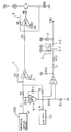
- the single drawing is a circuit diagram showing the principal part of a wire tension control apparatus according to one embodiment of the present invention.
- a wire-cut electrical discharge machine is so designed as to cause a wire delivered from a wire supply bobbin to run along a wire path, which is composed of a pinch roller, a brake roller, a guide roller, upper and lower guides, etc., and causes electrical discharge to generate between the wire and a workpiece, thereby effecting electrical discharge machining.
- the electrical discharge machine comprises an electromagnetic brake unit, shown by reference symbol B in the accompanying drawing, for braking the brake roller to apply a braking force on the wire, to thereby generate a wire tension, and a wire tension sensing unit which includes a cantilever.
- the cantilever is swingably supported at its one end, supports the wire guide roller for rotation at its other end, and is supported at its intermediate portion by a pressure sensing section of a load cell LC, for use as a tension sensor.
- the electrical discharge machine comprises a numerical control device CNC, which accommodates therein a computer, for controlling the operation of the electrical discharge machine and delivering a command voltage Tc, which is indicative of a set wire tension, and a wire tension control apparatus for driving the electromagnetic brake unit B in accordance with an output voltage Tf of the tension sensor, which is indicative of a detected wire tension, and a set wire tension voltage Tc, so as to feedback-control an actual wire tension to the set wire tension.
- the numerical control device CNC includes a manual data input unit MDI with a CRT display unit, and functions as display control means of the wire tension control apparatus for controlling the operation of the display unit.
- the wire tension control apparatus comprises a first operational amplifier OP1 for use as a differential amplifier 1 for outputting the difference between the set wire tension voltage Tc and the detected wire tension voltage Tf, a second operational amplifier OP2 for use as an amplifier 2 for amplifying the output of the operational amplifier OP1 and a transistor Q for controlling an exciting current flowing through an exciting coil of the electromagnetic brake unit B.
- the operational amplifier OP1 has its first input terminal connected to an output circuit of the numerical control device CNC through a resistor R1 and connected to the load cell LC through a resistor R2, and has its second input terminal grounded through a resistor R4.
- the output terminal of the first operational amplifier OP1 is connected to a first input terminal of this amplifier through a resistor R3, and is connected to a first input terminal of the second operational amplifier OP2 through a resistor R5.
- the second operational amplifier OP2 has its second input terminal grounded through a resistor R7, and its output terminal connected to the first input terminal of this amplifier through a resistor R6 and connected to the base of the transistor Q through a resistor R8.
- the collector of the transistor Q is connected to one end of the exciting coil of the electromagnetic brake unit B the other end of which is connected to a power source +Va, and the junction of the first input terminal of the second operational amplifier OP2 and the emitter of the transistor Q is grounded through a resistor R9.
- the wire tension control apparatus comprises a third operational amplifier OP3 for use as an inverting amplifier 4 for inverting the sign of the set wire tension voltage Tc, a voltage divider composed of resistors R10 and R11 whose resistance ratio ranges, e.g., from 9:1 to 8:2, and used to obtain a voltage at 10% to 20% of the output voltage of the operational amplifier OP3, and a comparator CP for comparing the divider output voltage and the detected wire tension voltage Tf.
- the third operational amplifier OP3 has its first input terminal connected to the output circuit of numerical control device through a resistor R14, its second input terminal grounded, and its output terminal connected to a resistor R10 and connected to the first input terminal through a resistor R15.
- the comparator CP has its first input terminal connected to the load cell LC and its second input terminal connected to the junction of the resistors R10 and R11. One end of the resistor R11 is grounded.
- the output terminal of the comparator CP is connected to a power source +Vb through a resistor R12, and is also connected, through an inverter 11 and a resistor R13, to the cathode of a light emitting diode 3-1 of a photocoupler 3 whose anode is connected to the power source +Vb.
- a phototransistor 3-2 of the photocoupler 3 has its collector connected to a power source +Vc, and its emitter connected to an input circuit of the numerical control device and to the anode of a diode D whose cathode is connected to the power source +Vc.
- An operator operates a keyboard of the manual data input unit MDI, thereby setting the set wire tension in the numerical control device CNC, and then causes the operation of the electrical discharge machine to start.
- the output of the first operational amplifier OP1 which is indicative of the difference between the set wire tension voltage Tc from the numerical control device CNC and the detected wire tension voltage Tf from the load cell LC, is applied to the transistor Q through the second operational amplifier OP2.
- an exciting current corresponding to the differential voltage (Tc - Tf) flows through the exciting coil of the electromagnetic brake unit B, and the braking force is applied to the running wire by means of the electromagnetic brake unit B, thereby generating the wire tension.
- the wire tension acts on the cantilever through the wire guide roller on the one end of the cantilever, thereby swinging the cantilever.
- a load corresponding to the actual wire tension acts on the load cell LC, and the detected wire tension voltage Tf corresponding to this load is delivered from the load cell.
- the detected wire tension voltage Tf is applied to the first operational amplifier OP1, and is also applied to the first input terminal of the comparator CP.
- the voltage divider output voltage whose sign is opposite to that of the set wire tension voltage Tc and whose magnitude is 10% to 20% of that of the voltage Tc, is applied to the second input terminal of the comparator CP through the third operational amplifier OP3.
- the actual wire tension is controlled so as to be equal to the set wire tension, so that the detected wire tension voltage Tf, which is applied to the first input terminal of the comparator CP, is higher than the divider output voltage.
- the ratio of the detected wire tension to the set wire tension exceeds a predetermined ratio of 1:10 to 1:5.
- a low level output is delivered from the comparator CP, so that the output of the inverter I1 goes high.
- the light emitting diode 3-1 of the photocoupler 3 is de-energized, so that no current flows through the phototransistor 3-2 of the photocoupler 3.
- the electromagnetic brake unit B goes wrong or is lowered in performance so that the wire tension control by means of the brake unit B becomes unusual, it typically results in a substantial reduction of the wire tension to less than 10% of the set wire tension.
- the detected wire tension voltage Tf is lower than the divider output voltage
- a high-level output is delivered from the comparator CP, and the output of the inverter I1 goes low.
- a driving current flows through the light emitting diode 3-1, thereby causing the light emitting diode to glow.
- a current flows through the phototransistor 3-2, that is, an alarm signal, which is indicative of an abnormal state of the brake unit B, is delivered from the photocoupler 3 to the input circuit of the numerical control device CNC.
- the numerical control device CNC cyclically executes a routine to monitor the presence/absence of the alarm signal, and causes the display unit to display on its CRT screen an alarm message to the effect that the brake unit in trouble, in response to the alarm signal Based on the display of this message, the operator checks or replaces the electromagnetic brake unit B with a new one.
- the load cell is used in the above embodiment, for example, any other tension sensor may be used instead.
- the division ratio of the set wire tension voltage Tc may be variably set by using variable resistor means for one or both of the resistors R10 and R11 which constitute the voltage divider.
- the operation of the electrical discharge machine may be automatically stopped in response to the alarm signal from the photocoupler 3.
Landscapes
- Chemical & Material Sciences (AREA)
- Chemical Kinetics & Catalysis (AREA)
- Electrochemistry (AREA)
- Engineering & Computer Science (AREA)
- Mechanical Engineering (AREA)
- Electrical Discharge Machining, Electrochemical Machining, And Combined Machining (AREA)
Applications Claiming Priority (2)
| Application Number | Priority Date | Filing Date | Title |
|---|---|---|---|
| JP2007187A JPH03213215A (ja) | 1990-01-18 | 1990-01-18 | ワイヤ張力制御装置 |
| JP7187/90 | 1990-01-18 |
Publications (2)
| Publication Number | Publication Date |
|---|---|
| EP0463178A1 true EP0463178A1 (de) | 1992-01-02 |
| EP0463178A4 EP0463178A4 (en) | 1992-08-19 |
Family
ID=11659051
Family Applications (1)
| Application Number | Title | Priority Date | Filing Date |
|---|---|---|---|
| EP19910902744 Withdrawn EP0463178A4 (en) | 1990-01-18 | 1991-01-18 | Wire tension controlling apparatus |
Country Status (3)
| Country | Link |
|---|---|
| EP (1) | EP0463178A4 (de) |
| JP (1) | JPH03213215A (de) |
| WO (1) | WO1991010530A1 (de) |
Cited By (1)
| Publication number | Priority date | Publication date | Assignee | Title |
|---|---|---|---|---|
| EP3037202A1 (de) * | 2014-12-26 | 2016-06-29 | Fanuc Corporation | Drahterosionsmaschine mit spannungsüberwachungsfunktion |
Families Citing this family (1)
| Publication number | Priority date | Publication date | Assignee | Title |
|---|---|---|---|---|
| JP5241916B2 (ja) * | 2009-04-07 | 2013-07-17 | 三菱電機株式会社 | ワイヤ放電加工機のワイヤ走行系保全システム |
Family Cites Families (4)
| Publication number | Priority date | Publication date | Assignee | Title |
|---|---|---|---|---|
| JPS57178619A (en) * | 1981-04-30 | 1982-11-02 | Sodeitsuku:Kk | Wire cut electric discharge machining device |
| JPS6017653B2 (ja) * | 1982-05-17 | 1985-05-04 | 株式会社牧野フライス製作所 | ワイヤカツト放電加工機のワイヤ電極断線検出装置 |
| JPS63256316A (ja) * | 1987-04-13 | 1988-10-24 | Mitsubishi Electric Corp | ワイヤ放電加工装置 |
| JPH01199726A (ja) * | 1988-02-03 | 1989-08-11 | Fanuc Ltd | ワイヤ張力,断線検出制御装置 |
-
1990
- 1990-01-18 JP JP2007187A patent/JPH03213215A/ja active Pending
-
1991
- 1991-01-18 EP EP19910902744 patent/EP0463178A4/en not_active Withdrawn
- 1991-01-18 WO PCT/JP1991/000052 patent/WO1991010530A1/ja not_active Ceased
Cited By (2)
| Publication number | Priority date | Publication date | Assignee | Title |
|---|---|---|---|---|
| EP3037202A1 (de) * | 2014-12-26 | 2016-06-29 | Fanuc Corporation | Drahterosionsmaschine mit spannungsüberwachungsfunktion |
| US10376975B2 (en) | 2014-12-26 | 2019-08-13 | Fanuc Corporation | Wire electric discharge machine with tension monitoring function |
Also Published As
| Publication number | Publication date |
|---|---|
| WO1991010530A1 (fr) | 1991-07-25 |
| EP0463178A4 (en) | 1992-08-19 |
| JPH03213215A (ja) | 1991-09-18 |
Similar Documents
| Publication | Publication Date | Title |
|---|---|---|
| US4977375A (en) | Fan operating status sensing circuit | |
| US4347993A (en) | Tension monitor means and system | |
| US5369999A (en) | Non-full state detecting apparatus and method | |
| US5546015A (en) | Determining device and a method for determining a failure in a motor compressor system | |
| US4019112A (en) | Battery checker circuit | |
| EP0355168B1 (de) | Regelanordung der metalldrahtspannung und nachweis eines bruches | |
| US4021635A (en) | Apparatus for controlling tool feed mechanism on an EDM machine | |
| EP0463178A1 (de) | Drahtspannungssteuerungseinrichtung | |
| US4703144A (en) | EDM control system to maximize efficiency by controlling the gap width | |
| US6024561A (en) | Monitoring for the presence of a flame in a burner | |
| EP0083731A1 (de) | Sicherheitsvorrichtung für eine Spulmaschine | |
| JPH0579626A (ja) | 石油燃焼器の制御方法及び装置 | |
| EP0667203A1 (de) | System zur drahtspannungssteuerung | |
| KR970000177A (ko) | 전기청소기 | |
| JPH0878185A (ja) | X線管の交換時期検知方法およびこれに用いる装置 | |
| JP3839512B2 (ja) | 超微小硬度測定装置 | |
| US3482236A (en) | Overload detection and indication | |
| JP3412228B2 (ja) | ガス遮断装置 | |
| US6028420A (en) | Constant voltage power supply with continuity checking | |
| KR930007959Y1 (ko) | 포토 커플러를 이용한 과전압 검출회로 | |
| JP2915158B2 (ja) | 検出装置の故障判別装置 | |
| JPH0631386Y2 (ja) | ポジショナの振動検出装置 | |
| KR0135363B1 (ko) | 전화기의 자기진단 방법 | |
| KR0128350B1 (ko) | 전자펌프 구동제어장치 및 그 방법 | |
| JPH06129402A (ja) | 電空変換器 |
Legal Events
| Date | Code | Title | Description |
|---|---|---|---|
| PUAI | Public reference made under article 153(3) epc to a published international application that has entered the european phase |
Free format text: ORIGINAL CODE: 0009012 |
|
| 17P | Request for examination filed |
Effective date: 19911009 |
|
| AK | Designated contracting states |
Kind code of ref document: A1 Designated state(s): CH DE LI |
|
| A4 | Supplementary search report drawn up and despatched |
Effective date: 19920702 |
|
| AK | Designated contracting states |
Kind code of ref document: A4 Designated state(s): CH DE LI |
|
| 17Q | First examination report despatched |
Effective date: 19930422 |
|
| STAA | Information on the status of an ep patent application or granted ep patent |
Free format text: STATUS: THE APPLICATION HAS BEEN WITHDRAWN |
|
| 18W | Application withdrawn |
Withdrawal date: 19940329 |