EP0463236B1 - Linearer Positionssensor - Google Patents
Linearer Positionssensor Download PDFInfo
- Publication number
- EP0463236B1 EP0463236B1 EP90125349A EP90125349A EP0463236B1 EP 0463236 B1 EP0463236 B1 EP 0463236B1 EP 90125349 A EP90125349 A EP 90125349A EP 90125349 A EP90125349 A EP 90125349A EP 0463236 B1 EP0463236 B1 EP 0463236B1
- Authority
- EP
- European Patent Office
- Prior art keywords
- silicon steel
- steel foil
- linear position
- position transducer
- turns
- Prior art date
- Legal status (The legal status is an assumption and is not a legal conclusion. Google has not performed a legal analysis and makes no representation as to the accuracy of the status listed.)
- Expired - Lifetime
Links
- 239000011888 foil Substances 0.000 claims abstract description 61
- 229910000976 Electrical steel Inorganic materials 0.000 claims abstract description 57
- 239000012212 insulator Substances 0.000 claims description 23
- 239000000853 adhesive Substances 0.000 claims description 18
- 230000001070 adhesive effect Effects 0.000 claims description 18
- 239000007767 bonding agent Substances 0.000 claims description 9
- 239000012777 electrically insulating material Substances 0.000 claims description 3
- XUIMIQQOPSSXEZ-UHFFFAOYSA-N Silicon Chemical compound [Si] XUIMIQQOPSSXEZ-UHFFFAOYSA-N 0.000 claims 1
- 239000003302 ferromagnetic material Substances 0.000 claims 1
- 229910052710 silicon Inorganic materials 0.000 claims 1
- 239000010703 silicon Substances 0.000 claims 1
- 230000000694 effects Effects 0.000 abstract description 6
- 239000000615 nonconductor Substances 0.000 abstract description 4
- 239000010410 layer Substances 0.000 description 22
- 239000000463 material Substances 0.000 description 21
- 229910000859 α-Fe Inorganic materials 0.000 description 12
- 230000035699 permeability Effects 0.000 description 10
- 239000000843 powder Substances 0.000 description 10
- 239000000203 mixture Substances 0.000 description 6
- RYGMFSIKBFXOCR-UHFFFAOYSA-N Copper Chemical compound [Cu] RYGMFSIKBFXOCR-UHFFFAOYSA-N 0.000 description 4
- XEEYBQQBJWHFJM-UHFFFAOYSA-N Iron Chemical compound [Fe] XEEYBQQBJWHFJM-UHFFFAOYSA-N 0.000 description 4
- 239000004020 conductor Substances 0.000 description 4
- 229910052802 copper Inorganic materials 0.000 description 4
- 239000010949 copper Substances 0.000 description 4
- 238000010276 construction Methods 0.000 description 3
- 230000004907 flux Effects 0.000 description 3
- 229910001209 Low-carbon steel Inorganic materials 0.000 description 2
- XAGFODPZIPBFFR-UHFFFAOYSA-N aluminium Chemical compound [Al] XAGFODPZIPBFFR-UHFFFAOYSA-N 0.000 description 2
- 229910052782 aluminium Inorganic materials 0.000 description 2
- 230000001419 dependent effect Effects 0.000 description 2
- 230000002500 effect on skin Effects 0.000 description 2
- 229910052742 iron Inorganic materials 0.000 description 2
- 238000004519 manufacturing process Methods 0.000 description 2
- 239000012790 adhesive layer Substances 0.000 description 1
- 239000011810 insulating material Substances 0.000 description 1
- 238000000034 method Methods 0.000 description 1
- 229920003223 poly(pyromellitimide-1,4-diphenyl ether) Polymers 0.000 description 1
- 230000008569 process Effects 0.000 description 1
- 230000037303 wrinkles Effects 0.000 description 1
Images

Classifications
-
- G—PHYSICS
- G01—MEASURING; TESTING
- G01D—MEASURING NOT SPECIALLY ADAPTED FOR A SPECIFIC VARIABLE; ARRANGEMENTS FOR MEASURING TWO OR MORE VARIABLES NOT COVERED IN A SINGLE OTHER SUBCLASS; TARIFF METERING APPARATUS; MEASURING OR TESTING NOT OTHERWISE PROVIDED FOR
- G01D5/00—Mechanical means for transferring the output of a sensing member; Means for converting the output of a sensing member to another variable where the form or nature of the sensing member does not constrain the means for converting; Transducers not specially adapted for a specific variable
- G01D5/12—Mechanical means for transferring the output of a sensing member; Means for converting the output of a sensing member to another variable where the form or nature of the sensing member does not constrain the means for converting; Transducers not specially adapted for a specific variable using electric or magnetic means
- G01D5/14—Mechanical means for transferring the output of a sensing member; Means for converting the output of a sensing member to another variable where the form or nature of the sensing member does not constrain the means for converting; Transducers not specially adapted for a specific variable using electric or magnetic means influencing the magnitude of a current or voltage
- G01D5/20—Mechanical means for transferring the output of a sensing member; Means for converting the output of a sensing member to another variable where the form or nature of the sensing member does not constrain the means for converting; Transducers not specially adapted for a specific variable using electric or magnetic means influencing the magnitude of a current or voltage by varying inductance, e.g. by a movable armature
- G01D5/2006—Mechanical means for transferring the output of a sensing member; Means for converting the output of a sensing member to another variable where the form or nature of the sensing member does not constrain the means for converting; Transducers not specially adapted for a specific variable using electric or magnetic means influencing the magnitude of a current or voltage by varying inductance, e.g. by a movable armature by influencing the self-induction of one or more coils
- G01D5/202—Mechanical means for transferring the output of a sensing member; Means for converting the output of a sensing member to another variable where the form or nature of the sensing member does not constrain the means for converting; Transducers not specially adapted for a specific variable using electric or magnetic means influencing the magnitude of a current or voltage by varying inductance, e.g. by a movable armature by influencing the self-induction of one or more coils by movable a non-ferromagnetic conductive element
-
- G—PHYSICS
- G01—MEASURING; TESTING
- G01B—MEASURING LENGTH, THICKNESS OR SIMILAR LINEAR DIMENSIONS; MEASURING ANGLES; MEASURING AREAS; MEASURING IRREGULARITIES OF SURFACES OR CONTOURS
- G01B7/00—Measuring arrangements characterised by the use of electric or magnetic techniques
- G01B7/02—Measuring arrangements characterised by the use of electric or magnetic techniques for measuring length, width or thickness
Definitions
- This invention relates to transducers in general, and more particularly to transducers for measuring straight line motion.
- the transducer disclosed in U.S. Patent No. 4,667,158 comprises a hollow tube-like bobbin 1 (formed out of an electrically insulating material such as plastic); a helical coil 2 (formed out of a good electrical conductor such as copper) wound around the outer surface of bobbin 1; a cylindrical rod or tube 3 (formed out of a good electrical conductor having low magnetic permeability such as copper or aluminum), with the rod being axially movable within bobbin 1; an attachment rod 3A connecting rod 3 with the object whose motion is to be measured; an outer shield tube 4 (formed out of a material having both high electrical conductivity and high magnetic permeability such as soft iron or low carbon steel), the shield tube 4 surrounding the remainder of the transducer and confining magnetic flux generated by current flowing through coil 2 to the interior of the transducer and shielding coil 2 from stray fields; and a tubular layer 13 (formed out of a material having high magnetic permeability and low electrical
- tubular layer 13 disposed between coil 2 and outer shield tube 4 is described (at column 6, lines 8-12) as being a ferrite material having a high magnetic permeability but a low electrical conductivity.
- ferrite 13 is preferably a ferrite powder distributed within a hardened bonding agent.
- tubular layer 13 out of ferrite powder as described above can result in performance variations as the temperature of the transducer varies, and can reduce the accuracy of the transducer if not evenly mixed and distributed.
- the principal object of the present invention is to provide a suitable alternative to the ferrite powder composition used to form the tubular layer 13 described in U.S. Patent No. 4,667,158.
- Another object of the present invention is to provide a new linear position transducer which is relatively fast, simple and inexpensive to manufacture, and which is reliable in operation.
- Still another object of the present invention is to provide a new linear position transducer which has improved temperature performance and which offers an improved signal to noise ratio.
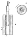
- FIGs. 3 and 4 there is shown an improved linear position transducer 100 formed in accordance with the present invention.
- Transducer 100 is substantially identical to the linear position transducer disclosed in U.S. Patent No. 4,667,158, except as will be hereinafter described in detail. More specifically, transducer 100 comprises a hollow tube-like bobbin 101 (formed out of an electrically insulating material such as plastic) having a length at least substantially four times its outside diameter; a helical coil 102 (formed out of a good electrical conductor such as copper) wound around the outer surface of bobbin 101 and having its ends 102A, 102B connected to suitable terminal pins (not shown); a cylindrical rod or tube 103 (formed out of a good electrical conductor having low magnetic permeability such as copper or aluminum), with the rod being axially movable within bobbin 101; an attachment rod 103A connecting rod 103 with the object whose motion is to be measured; an outer shield tube 104 (formed out of a material having both high electrical conductivity and high magnetic permeability such as soft iron or low carbon steel), the shield tube 104 surrounding the remainder of the transducer and
- bobbin 101 of transducer 100 is substantially the same as bobbin 1 of the transducer disclosed in U.S. Patent No. 4,557,158; helical coil 102 of transducer 100 is substantially the same as helical coil 2 of the transducer disclosed in U.S. Patent No. 4,557,158; cylindrical rod 103 of transducer 100 is substantially the same as cylindrical rod 3 of the transducer disclosed in U.S. Patent No. 4,557,158; attachment rod 103A of transducer 100 is substantially the same as attachment rod 3A of the transducer disclosed in U.S. Patent No. 4,557,158; and outer shield tube 104 of transducer 100 is substantially the same as outer shield tube 4 of the transducer disclosed in U.S. Patent No. 4,557,158.
- element 113 of transducer 100 is analogous to tubular layer 13 of the transducer disclosed in U.S. Patent No. 4,557,158, although it differs substantially in construction, as will hereinafter be described in detail.
- element 113 is formed so as to have, overall, a high magnetic permeability and as low an electrical conductivity as possible, so as to have the effect of reducing the reluctance of the space between coil 102 and shield 104 without providing a current path between coil 102 and shield 104.
- Element 113 comprises one or more sheets of silicon steel foil 113A which are coated with an electrical insulator 113B on at least one side thereof.
- Foil 113A is wound around itself, with insulator 113B to the outside, is slipped into the space between coil 102 and outer shield tube 104, and is then allowed to unroll until it comes into contact with outer shield tube 104. As this occurs, the insulator 113B will contact outer shield tube 104 and prevent foil 113A from coming into direct electrical contact with shield tube 104.
- foil 113A comprises grain oriented, cold rolled 3% silicon steel having a thickness of about 0,00254 cm (.001 of an inch).
- silicon steel foil is available from a wide variety of sources, e.g. it might comprise silicon steel foil sold by Allegheny Ludlum under the tradename Silectron.
- foil 113A is such that there are at least 6 turns of the foil disposed between coil 102 and outer shield tube 104. In practice, it has been found that using 3 sheets of silicon steel foil, which when rolled produce a total of 9 turns, works well. Of course, depending on the transducer performance characteristics desired, it is possible to use less turns of the silicon steel foil. In practice, it has been found that the fewer the number of turns of silicon steel foil used, the more non-linear the transducer's performance characteristics. In addition, using fewer turns of the silicon steel foil appears to worsen the temperature performance of the transducer.
- each turn of the silicon steel foil 113A is kept very thin to minimize potential core losses.
- insulator 113B comprises a material which will act as both an insulator (to prevent the outer layer of silicon steel foil 113A from coming into direct electrical contact with shield tube 104, and to prevent adjacent layers of the silicon steel foil 113A from coming into contact with one another) and as an adhesive to hold the silicon steel foil 113A in position within the transducer. It is important that the insulator 113B be relatively temperature stable and non-hygroscopic, as well as insulating. A satisfactory insulating/adhesive material is available from a wide variety of sources, e.g. it might comprise the insulating/adhesive material sold by W.J. Ruscoe Company of Akron, Ohio under the tradename PLIOBOND.
- the insulating/adhesive material is applied to the outer surface of silicon steel foil 113A to a sufficient thickness that it will form a uniform, effective insulating/adhesive layer, e.g. it might be spread to a thickness of approximately 0,00508 cm (.002 of an inch) when wet.
- the insulating/adhesive material may be sprayed on to the outer surface of silicon steel foil 113A or it may be applied in other ways well known in the art. It is important that the insulating/adhesive material be sufficiently viscous that it will not run after it has been applied to the outer surface of silicon steel foil 113A.
- the insulating/adhesive material may be heat set if necessary to bind the silicon steel foil 113A securely within the transducer.
- the insulating/adhesive material may comprise a sheet of insulating/adhesive material attached to the outer surface of silicon steel foil 113A.
- insulator 113B comprises a material which functions solely as an insulator and does not also function as an adhesive
- an additional adhesive material may be added on top of the insulating material to effect proper bonding of the silicon steel layers to one another and to shield tube 104.
- insulator 113B could comprise an electrically insulative tape such as Kapton (R) tape, having a thickness of about 0,00254 cm (.001 of an inch).
- R Kapton
- an adhesive material must be added to the outside surface of the tape to effect proper bonding of the silicon steel layers to one another and to shield tube 104.
- Foil 113A and electrical insulator 113B together form the element 113 which provides a layer which has high magnetic permeability, whereby the reluctance of the space between coil 102 and shield tube 104 will be reduced to a low value.
- electrical insulator 113B will prevent coil 102 from making direct electrical contact with shield tube 104, so that no current path will be provided between coil 102 and shield 104.
- the transducer When forming the transducer in accordance with the foregoing construction, it is important to minimize any stress in the silicon steel foil 113A since the magnetic permeability of the foil will vary with the amount of applied stress. It is also important that the layers of silicon steel foil 113A be uniformly positioned within the transducer, with no wrinkles in the foil, etc., since the linearity of the transducer is dependent on the uniformity of the flux field within the transducer, which is in turn dependent on the uniformity of the silicon steel layers.
- a bonding agent 114 may be used to fill the space between coil 102 and layer 113.
- Bonding agent 114 must be formed out of a material which is temperature stable and non-hygroscopic, as well as insulating.
- Bonding agent 114 may comprise the same insulating/adhesive material used to form insulator 113B (except that, in this case, it would be formed somewhat more viscous than the material used for insulator 113B, to permit the bonding agent to flow into the transducer shell), or it might comprise a different bonding agent, such as that well known in the art.
- the two ends of the transducer are capped in ways well known in the art (not shown) to prevent the creation of any direct current paths between the transducer elements previously described, while still providing electrical access to the ends 102A, 102B of coil 102.
- an improved linear position transducer can be formed which has superior temperature performance and an improved signal to noise ratio.
- the present invention provides a suitable alternative to the ferrite powder composition used to form the tubular layer 13 described in U.S. Patent No. 4,667,158.
- a new linear position transducer which has improved temperature performance and which offers an improved signal to noise ratio.
Landscapes
- Physics & Mathematics (AREA)
- General Physics & Mathematics (AREA)
- Transmission And Conversion Of Sensor Element Output (AREA)
- Measurement Of Length, Angles, Or The Like Using Electric Or Magnetic Means (AREA)
- Vehicle Body Suspensions (AREA)
- Switches That Are Operated By Magnetic Or Electric Fields (AREA)
- Shielding Devices Or Components To Electric Or Magnetic Fields (AREA)
Claims (17)
- Linearer Positionssensor, bestehend aus:a) einer Röhre (101) elektrisch isolierenden Materials mit einer Länge von mindestens dem Vierfachen ihres Außendurchmessers;b) einer wendelförmigen, leitenden Spule (102), die um die besagte Röhre gewunden ist und mindestens viermal so lang ist wie der besagte Durchmesser;c) einem verlängerten Kern (103) von elektrisch leitfähigem, nicht-ferromagnetischem Material anliegend in der besagten Röhre (101) aufgenommen, und innerhalb derselben in axialer Bewegungsrichtung gleitfähig angeordnet
dadurch gekennzeichnet, daßd) mindestens eine Lage einer Siliziumstahlfolie (113a) die besagte Spule (102) umgibt, wobei die besagte Siliziumstahlfolie (113a) mindestens viermal so lang ist wie der besagte Durchmesser. - Linearer Positionssensor nach Anspruch 1, wobei eine elektrisch leitfähige Abschirmung (104) die besagte, mindestens einfache Lage der Siliziumstahlfolie (113a) umgibt, und wobei weiterhin ein Isolator (113b) zwischen der besagten Abschirmung (104) und der besagten, mindestens einfachen Lage aus Siliziumstahlfolie (113a) angeordnet ist, um einen Stromfluß zwischen der besagten Abschirmung (104) und der besagten, mindestens einfachen Lage aus Siliziumstahlfolie (113a) zu verhindern.
- Linearer Positionssensor nach Anspruch 2, wobei die besagte, mindestens einfache Lage aus Siliziumstahlfolie (113a) eine innere, der besagten Spule (102) zugewandte Oberfläche umfaßt, sowie eine äußere, der besagten Abschirmung (104) zugewandte Oberfläche, und wobei ferner der besagte Isolator (113b) an der äußeren Oberfläche der besagten, mindestens einfachen Lage aus Siliziumstahlfolie (113a) befestigt ist.
- Linearer Positionssensor nach Anspruch 3, wobei der besagte Isolator (113b) als Klebemittel ausgebildet ist, um die besagte, mindestens einfache Lage aus Siliziumstahlfolie (113a) mit der besagten Abschirmung (104) zu verbinden.
- Linearer Positionssensor nach Anspruch 4, wobei der besagte Isolator (113b) etwa 0,00508 cm dick ist.
- Linearer Positionssensor nach Anspruch 3, wobei ein Klebemittel zwischen dem besagten Isolator (113b) und der besagten Abschirmung (104) angeordnet ist, um die besagte, mindestens einfache Lage aus Siliziumstahlfolie (113a) mit der besagten Abschirmung (104) zu verbinden.
- Linearer Positionssensor nach Anspruch 6, wobei der besagte Isolator (113b) aus einem isolierenden Band besteht und wobei ferner das besagte Klebemittel zwischen dem besagten, isolierenden Band und der besagten Abschirmung (104) angeordnet ist.
- Linearer Positionssensor nach Anspruch 7, wobei das besagte, isolierende Band eine Dicke von etwa 0,00254 cm aufweist.
- Linearer Positionssensor nach Anspruch 1, wobei die besagte, mindestens einfache Lage aus Siliziumstahlfolie (113a) mindestens sechs Windungen aus Siliziumstahlfolie aufweist, wobei jede Windung der Siliziumstahlfolie aus kornorientierter, kaltgewalzter 3%-Siliziumstahlfolie mit einer Dicke von etwa 0,00254 cm besteht.
- Linearer Positionssensor nach Anspruch 9, wobei eine röhrenförmige, elektrisch leitfähige Abschirmung (104) die äußere Umwindung der besagten, mindestens sechs Windungen aus Siliziumstahlfolie (113a) umgibt, und wobei ferner jede Umwindung der besagten, mindestens sechs Windungen der Siliziumstahlfolie (113a) eine innere, der besagten Spule (102) zugewandte Oberfläche sowie eine äußere, der besagten Abschirmung (104) zugewandte Oberfläche aufweist, und wobei ferner ein Isolator (113b) an der äußeren Oberfläche jeder Umwindung der besagten, mindestens sechs Windungen der Siliziumstahlfolie (113a) angeordnet ist, uma) einen Stromfluß zwischen der besagten Abschirmung und der äußeren Umwindung der besagten, mindestens sechs Windungen der Siliziumstahlfolie (113a) zu verhindern undb) einen radialen Stromfluß zwischen aneinandergrenzenden Windungen der besagten, mindestens sechs Windungen aus Siliziumstahlfolie (113a) zu vermeiden.
- Linearer Positionssensor nach Anspruch 10, wobei der besagte Isolator, (113b) auch ein Klebemittel bildet, um die besagten, mindestens sechs Windungen der Siliziumstahlfolie (113a) aneinander zu binden und um die äußere Windung der besagten, mindestens sechs Windungen aus Siliziumstahlfolie (113a) mit der besagten Abschirmung (104) zu verbinden.
- Linearer Positionssensor nach Anspruch 11, wobei der besagte Isolator (113b) etwa 0,00508 cm dick ist.
- Linearer Positionssensor nach Anspruch 10, wobei ein Klebemittel, auf dem die äußere Oberfläche jeder Windung der besagten, mindestens sechs Windungen der Siliziumstahlfolie (113a) bedeckenden Isolator (113b) aufgebracht ist, um die besagten, mindestens sechs Windungen der Siliziumstahlfolie (113a) miteinander zu verbinden, und um die äußere Windung der besagten, mindestens sechs Windungen der Siliziumstahlfolie (113a) mit der besagten Abschirmung (104) zu verbinden.
- Linearer Positionssensor nach Anspruch 13, wobei der besagte Isolator (113b) aus einem isolierenden Band gebildet ist, welches auf der äußeren Oberfläche jeder Umwindung der besagten, mindestens sechs Windungen der Siliziumstahlfolie (113a) angeordnet ist.
- Linearer Positionssensor nach Anspruch 14, wobei das besagte, isolierende Band eine Dicke von etwa 0,00254 cm aufweist.
- Linearer Positionssensor nach Anspruch 1, wobei die mindestens einfache Lage aus Siliziumstahlfolie (113a) neun Windungen aus Siliziumstahlfolie umfaßt, und wobei ferner jede der besagten Windungen eine Dicke von etwa 0,00254 cm aufweist und aus kornorientierter, kaltgewalzter 3%-Siliziumstahlfolie gebildet ist.
- Linearer Positionssensor nach Anspruch 1, wobei ein Bindemittel zwischen der besagten Spule (102) und der besagten, mindestens einfachen Lage aus Siliziumstahlfolie (113a) angeordnet ist.
Priority Applications (1)
| Application Number | Priority Date | Filing Date | Title |
|---|---|---|---|
| AT90125349T ATE96901T1 (de) | 1990-06-22 | 1990-12-22 | Linearer positionssensor. |
Applications Claiming Priority (2)
| Application Number | Priority Date | Filing Date | Title |
|---|---|---|---|
| US542152 | 1990-06-22 | ||
| US07/542,152 US5068607A (en) | 1990-06-22 | 1990-06-22 | Electrical linear position transducer with silicon steel foil shield surrounding transducer coil |
Publications (2)
| Publication Number | Publication Date |
|---|---|
| EP0463236A1 EP0463236A1 (de) | 1992-01-02 |
| EP0463236B1 true EP0463236B1 (de) | 1993-11-03 |
Family
ID=24162558
Family Applications (1)
| Application Number | Title | Priority Date | Filing Date |
|---|---|---|---|
| EP90125349A Expired - Lifetime EP0463236B1 (de) | 1990-06-22 | 1990-12-22 | Linearer Positionssensor |
Country Status (5)
| Country | Link |
|---|---|
| US (1) | US5068607A (de) |
| EP (1) | EP0463236B1 (de) |
| JP (1) | JP3122851B2 (de) |
| AT (1) | ATE96901T1 (de) |
| DE (1) | DE69004421T2 (de) |
Families Citing this family (11)
| Publication number | Priority date | Publication date | Assignee | Title |
|---|---|---|---|---|
| DE3910297A1 (de) * | 1989-03-30 | 1990-10-04 | Micro Epsilon Messtechnik | Beruehrungslos arbeitendes wegmesssystem |
| US5350397A (en) | 1992-11-13 | 1994-09-27 | Target Therapeutics, Inc. | Axially detachable embolic coil assembly |
| US5453685A (en) * | 1993-07-30 | 1995-09-26 | Philips Electronics North America Corporation | Inductive position sensing device and apparatus with selectable winding configuration |
| DE19500982C2 (de) * | 1995-01-14 | 1997-07-17 | Bosch Gmbh Robert | Weggeber |
| DE19806529C2 (de) * | 1998-02-17 | 2002-04-18 | Micro Epsilon Messtechnik | Weg-Winkel-Sensor |
| DE10025661A1 (de) | 2000-05-24 | 2001-12-06 | Balluff Gebhard Feinmech | Wegmeßsystem |
| US6828780B2 (en) | 2001-05-01 | 2004-12-07 | Balluff Gmbh | Position measuring system having an inductive element arranged on a flexible support |
| RU2485439C2 (ru) * | 2011-07-26 | 2013-06-20 | Сергей Александрович Матюнин | Индуктивный датчик линейного перемещения |
| SE541400C2 (en) * | 2017-02-27 | 2019-09-17 | Sem Ab | Inductive position sensor with improved plunger core design |
| US11324120B2 (en) * | 2017-03-08 | 2022-05-03 | Sumitomo Electric Printed Circuits, Inc. | Flexible printed circuit board |
| SE541423C2 (en) * | 2018-01-26 | 2019-09-24 | Borgwarner Sweden Ab | An electrical motor |
Family Cites Families (3)
| Publication number | Priority date | Publication date | Assignee | Title |
|---|---|---|---|---|
| DE3346643A1 (de) * | 1983-12-23 | 1985-07-04 | Standard Elektrik Lorenz Ag, 7000 Stuttgart | Sensor fuer magnetisierbare materialien |
| US4667158A (en) * | 1985-04-01 | 1987-05-19 | Redlich Robert W | Linear position transducer and signal processor |
| GB8810214D0 (en) * | 1988-04-29 | 1988-06-02 | Lucas Ind Plc | Movement transducer |
-
1990
- 1990-06-22 US US07/542,152 patent/US5068607A/en not_active Expired - Fee Related
- 1990-12-22 EP EP90125349A patent/EP0463236B1/de not_active Expired - Lifetime
- 1990-12-22 AT AT90125349T patent/ATE96901T1/de not_active IP Right Cessation
- 1990-12-22 DE DE90125349T patent/DE69004421T2/de not_active Expired - Fee Related
-
1991
- 1991-06-21 JP JP03177671A patent/JP3122851B2/ja not_active Expired - Fee Related
Also Published As
| Publication number | Publication date |
|---|---|
| ATE96901T1 (de) | 1993-11-15 |
| DE69004421D1 (de) | 1993-12-09 |
| DE69004421T2 (de) | 1994-03-10 |
| JPH04252902A (ja) | 1992-09-08 |
| JP3122851B2 (ja) | 2001-01-09 |
| EP0463236A1 (de) | 1992-01-02 |
| US5068607A (en) | 1991-11-26 |
Similar Documents
| Publication | Publication Date | Title |
|---|---|---|
| US4667158A (en) | Linear position transducer and signal processor | |
| US5068607A (en) | Electrical linear position transducer with silicon steel foil shield surrounding transducer coil | |
| CN1005931B (zh) | 测量导电体中电流的测量用变换器 | |
| US3688187A (en) | Eddy current position transducer utilizing a coil whose impedance is made substantially ohmic | |
| US4267508A (en) | Apparatus for non-contact measurement of distance from a metallic body using a detection coil in the feedback circuit of an amplifier | |
| US3694785A (en) | Temperature compensating differential transformer | |
| JPS5937846B2 (ja) | 計器用変成器 | |
| GB2034487A (en) | Alternating current measuring devices | |
| US4857824A (en) | Movable core position transducer | |
| US6310472B1 (en) | Multiple hall effect sensor of magnetic core displacement | |
| KR970022216A (ko) | 차동트랜스 및 그것을 사용한 측정장치 | |
| EP0595367A1 (de) | Weggeber mit gegenüberliegenden Spulen für verbesserte Linearität und Temperaturkompensation | |
| GB2240184A (en) | Measuring device for determining an angle of rotation | |
| US5206587A (en) | Inductive displacement transducer having telescoping probe assembly | |
| US3113280A (en) | Electro-magnetic means for measuring a mechanical excursion | |
| JP2000147023A (ja) | 感度調整機能付き大口径電流プローブ | |
| US4629974A (en) | Active current transformer | |
| US5089930A (en) | Temperature compensated linear variable transformer | |
| US3835370A (en) | Dampened choke coil | |
| US3546648A (en) | Linear variable differential transformer | |
| US3356933A (en) | Displacement sensor comprising differential transformer with nonmagnetic core | |
| JPH09210610A (ja) | 外部磁気や金属等の影響防止の高周波励磁差動トランス | |
| US2452679A (en) | Radio-frequency transformer | |
| JP3352983B2 (ja) | 滑り誘導子リアクター構造 | |
| GB2295459A (en) | Alternating current sensor |
Legal Events
| Date | Code | Title | Description |
|---|---|---|---|
| PUAI | Public reference made under article 153(3) epc to a published international application that has entered the european phase |
Free format text: ORIGINAL CODE: 0009012 |
|
| AK | Designated contracting states |
Kind code of ref document: A1 Designated state(s): AT BE CH DE FR GB IT LI NL SE |
|
| 17P | Request for examination filed |
Effective date: 19911111 |
|
| 17Q | First examination report despatched |
Effective date: 19930324 |
|
| GRAA | (expected) grant |
Free format text: ORIGINAL CODE: 0009210 |
|
| AK | Designated contracting states |
Kind code of ref document: B1 Designated state(s): AT BE CH DE FR GB IT LI NL SE |
|
| REF | Corresponds to: |
Ref document number: 96901 Country of ref document: AT Date of ref document: 19931115 Kind code of ref document: T |
|
| REF | Corresponds to: |
Ref document number: 69004421 Country of ref document: DE Date of ref document: 19931209 |
|
| ITF | It: translation for a ep patent filed | ||
| ET | Fr: translation filed | ||
| PLBE | No opposition filed within time limit |
Free format text: ORIGINAL CODE: 0009261 |
|
| STAA | Information on the status of an ep patent application or granted ep patent |
Free format text: STATUS: NO OPPOSITION FILED WITHIN TIME LIMIT |
|
| 26N | No opposition filed | ||
| EAL | Se: european patent in force in sweden |
Ref document number: 90125349.2 |
|
| PGFP | Annual fee paid to national office [announced via postgrant information from national office to epo] |
Ref country code: NL Payment date: 19951213 Year of fee payment: 6 |
|
| PGFP | Annual fee paid to national office [announced via postgrant information from national office to epo] |
Ref country code: AT Payment date: 19951214 Year of fee payment: 6 |
|
| PGFP | Annual fee paid to national office [announced via postgrant information from national office to epo] |
Ref country code: CH Payment date: 19951229 Year of fee payment: 6 Ref country code: BE Payment date: 19951229 Year of fee payment: 6 |
|
| PG25 | Lapsed in a contracting state [announced via postgrant information from national office to epo] |
Ref country code: AT Effective date: 19961222 |
|
| PG25 | Lapsed in a contracting state [announced via postgrant information from national office to epo] |
Ref country code: LI Effective date: 19961231 Ref country code: CH Effective date: 19961231 Ref country code: BE Effective date: 19961231 |
|
| BERE | Be: lapsed |
Owner name: DATA INSTRUMENTS G.M.B.H. Effective date: 19961231 |
|
| PG25 | Lapsed in a contracting state [announced via postgrant information from national office to epo] |
Ref country code: NL Effective date: 19970701 |
|
| REG | Reference to a national code |
Ref country code: CH Ref legal event code: PL |
|
| NLV4 | Nl: lapsed or anulled due to non-payment of the annual fee |
Effective date: 19970701 |
|
| PGFP | Annual fee paid to national office [announced via postgrant information from national office to epo] |
Ref country code: FR Payment date: 20001204 Year of fee payment: 11 |
|
| REG | Reference to a national code |
Ref country code: GB Ref legal event code: IF02 |
|
| PGFP | Annual fee paid to national office [announced via postgrant information from national office to epo] |
Ref country code: GB Payment date: 20020619 Year of fee payment: 12 |
|
| PGFP | Annual fee paid to national office [announced via postgrant information from national office to epo] |
Ref country code: SE Payment date: 20020628 Year of fee payment: 12 Ref country code: DE Payment date: 20020628 Year of fee payment: 12 |
|
| PG25 | Lapsed in a contracting state [announced via postgrant information from national office to epo] |
Ref country code: FR Free format text: LAPSE BECAUSE OF NON-PAYMENT OF DUE FEES Effective date: 20020830 |
|
| REG | Reference to a national code |
Ref country code: FR Ref legal event code: ST |
|
| PG25 | Lapsed in a contracting state [announced via postgrant information from national office to epo] |
Ref country code: GB Free format text: LAPSE BECAUSE OF NON-PAYMENT OF DUE FEES Effective date: 20021222 |
|
| PG25 | Lapsed in a contracting state [announced via postgrant information from national office to epo] |
Ref country code: SE Free format text: LAPSE BECAUSE OF NON-PAYMENT OF DUE FEES Effective date: 20021223 |
|
| PG25 | Lapsed in a contracting state [announced via postgrant information from national office to epo] |
Ref country code: DE Free format text: LAPSE BECAUSE OF NON-PAYMENT OF DUE FEES Effective date: 20030701 |
|
| EUG | Se: european patent has lapsed | ||
| GBPC | Gb: european patent ceased through non-payment of renewal fee |
Effective date: 20021222 |
|
| PG25 | Lapsed in a contracting state [announced via postgrant information from national office to epo] |
Ref country code: IT Free format text: LAPSE BECAUSE OF NON-PAYMENT OF DUE FEES;WARNING: LAPSES OF ITALIAN PATENTS WITH EFFECTIVE DATE BEFORE 2007 MAY HAVE OCCURRED AT ANY TIME BEFORE 2007. THE CORRECT EFFECTIVE DATE MAY BE DIFFERENT FROM THE ONE RECORDED. Effective date: 20051222 |