EP0463258B1 - Siebdruckvorrichtung - Google Patents
Siebdruckvorrichtung Download PDFInfo
- Publication number
- EP0463258B1 EP0463258B1 EP90312912A EP90312912A EP0463258B1 EP 0463258 B1 EP0463258 B1 EP 0463258B1 EP 90312912 A EP90312912 A EP 90312912A EP 90312912 A EP90312912 A EP 90312912A EP 0463258 B1 EP0463258 B1 EP 0463258B1
- Authority
- EP
- European Patent Office
- Prior art keywords
- cylinder
- print frame
- silk
- operation piece
- printing
- Prior art date
- Legal status (The legal status is an assumption and is not a legal conclusion. Google has not performed a legal analysis and makes no representation as to the accuracy of the status listed.)
- Expired - Lifetime
Links
- 238000007650 screen-printing Methods 0.000 title claims description 12
- 238000007639 printing Methods 0.000 claims description 35
- 238000004140 cleaning Methods 0.000 description 5
- 238000006243 chemical reaction Methods 0.000 description 1
- 230000006835 compression Effects 0.000 description 1
- 238000007906 compression Methods 0.000 description 1
- 238000010276 construction Methods 0.000 description 1
- 238000006073 displacement reaction Methods 0.000 description 1
- 238000000034 method Methods 0.000 description 1
- 230000003252 repetitive effect Effects 0.000 description 1
Images




Classifications
-
- B—PERFORMING OPERATIONS; TRANSPORTING
- B41—PRINTING; LINING MACHINES; TYPEWRITERS; STAMPS
- B41F—PRINTING MACHINES OR PRESSES
- B41F15/00—Screen printers
- B41F15/08—Machines
- B41F15/0804—Machines for printing sheets
- B41F15/0813—Machines for printing sheets with flat screens
- B41F15/0827—Machines for printing sheets with flat screens with a stationary squeegee and a moving screen
Definitions
- This invention relates to silk-screen printing apparatus generally of the type which includes a rotatable cylinder and more particularly to such apparatus capable of moving a print frame independently from its cylinder.
- a cleaning method for the purpose stated above is disclosed in U.S. Patent No. 4,448,124.
- a paper ejecting base 101 is installed in a swingable manner as shown in Fig. 6.
- the paper ejecting base 101 is held in a horizontal orientation as indicated by the two-dot chain.
- a recovering device not shown in the drawings.
- the paper ejecting base 101 is swung in the direction indicated by the arrow in Figure 6 to the suspended position indicated by solid lines. This opens the space below the print frame 102. Thus an operator can lean into the printing machine to wipe ink from the bottom face of silk-screen 103 and the periphery of the cylinder 100.
- the print frame 102 Since the print frame 102 is located at the rear of the cylinder 100 within the machine, the operator has to lean the upper portion of his body into the machine in order to wipe ink from the entire cylinder and silk-screen. However, gaining access to the limited space in the machine can be difficult. As a result, when a large operator tries to wipe ink from the inner parts, ink sometimes remains partially unremoved. The remaining ink sticks firmly on the rear face of silk-screen 103, thereby obstructing good printing operation thereafter.
- the present invention seeks to provide a silk-screen printing apparatus which is capable of assuring reliable cleaning of the cylinder regardless of the size of the operator.
- the invention seeks to provide silk-screen printing apparatus having a print frame that can be easily pulled from the machine base to provide a wide space inside the machine base.
- the invention provides silk-screen printing apparatus, which comprises a cylinder installed in a rotatable manner within a machine base, and a print frame which is located above the cylinder, the print frame being linked to the cylinder during printing so as to reciprocate in a horizontal direction in synchronisation with the rotation of the cylinder, and being capable of performing the printing work on paper held on the cylinder through a silk-screen provided in the print frame by means of a squeegee and a doctor, the apparatus being characterised in that it includes:
- the silk-screen printing apparatus of the invention performs a printing operation by moving a silk-screen in synchronization with the rotation of a cylinder located inside a machine base.
- the printing apparatus includes a print frame located above the cylinder for carrying the silk-screen.
- the print screen is linked with the cylinder during printing and reciprocates in the horizontal direction in synchronization with the rotation of the cylinder.
- a releasing mechanism may be operable during non-printing times to release the linkage between the print frame and the cylinder, so as to allow movement of the print frame independent from the rotation of said cylinder.
- the printing apparatus includes a paper ejecting base installed on the machine base in a swingable manner between a horizontal position and a suspended position.
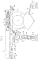
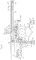
- a cylinder 2 is supported in a rotatable manner at the center in a machine base 1.
- a horizontally extending rail 25 is mounted to the inner wall surface of the machine base 1 above the cylinder 2.
- a print frame 3 having a rectangular loop shape is located above the rail 25.
- a silk-screen 4 is located inside the loop of the print frame.
- a squeegee 6 and a doctor 5 are mounted on a mounting plate 7, which is fixed to the machine base 1 above the cylinder 2.
- the silk-screen 4 is located between the cylinder and the mounting plate.
- a paper ejecting plate 8 is provided at a paper ejecting side (at the left side in the figure) of the machine base 1 and can be swung between the horizontal position shown by the solid line in Figure 1 and the suspended position shown by the two-dot chain line. During printing operation, the paper ejecting plate 8 is in horizontal position. In this position, it feeds printing paper to a recovering device (not shown). During non-printing times, it is swung to the suspended position thereby widening the space at the paper ejecting side of the machine base 1.
- Drive gears 9 are fixed to opposing ends of said cylinder 2.
- the drive gears 9 have a diameter larger than that of the cylinder. These drive gears 9 are respectively engaged with racks 10 formed on the bottom faces of opposing sides of print frame 3.
- a driven gear 11 is fixed to the shaft of cylinder 2 at a position adjacent one of the drive gears 9.
- the driven gear 11 has a smaller diameter than cylinder 2 and engages a sector gear 12.
- Rotation of an electric motor 13 is transmitted as a reciprocating motion to the sector gear 12 through a motion conversion mechanism comprising two rods 15.
- the sector gear 12 makes reciprocating rotation within a prescribed range. Reciprocal rotation of said sector gear 12 drives the cylinder 2 in a reciprocating manner through the driven gear 11.
- the reciprocating rotation of the cylinder 3 is transmitted to the rack 10 through the drive gear 9, and the print frame 3 makes a reciprocating motion back and forth in synchronization with the cylinder 2.
- a recessed mounting portion 16 is formed in the length direction at a part of the bottom face of each side of the print frame 3.
- a channel-shaped mounting member 17 is attached to the recessed mounting portion 16.
- a pair of through holes 18 are made in the print frame 3 above the recessed mounting portion 16.
- a pair of supporting holes 19 are made in the print frame 3 adjacent the operation piece 17.
- a pair of washer-shaped guides 20a are supported in a rotatable manner by the print frame 3 by means of shafts 20. These guides are provided at both the ends of operation piece 17.
- a rack 21 is formed throughout the whole length and width of the operation piece for engagement with the drive gear 5.
- a pair of holding walls 24 extend upward from the bottom at both sides of the operation piece 17.
- the operation piece 17 is attached to the print frame 3 in a manner such that the recessed mounting portion 16 can be covered by both the holding walls 24.
- Front and rear slots 22 are made in each holding wall 24.
- Pins 23 are inserted into both the slots 22 and supporting holes 18 in order to support the operation piece 17 in a vertically movable manner relative to the print frame 3.
- the operation piece 17 can move between an upper position ( Figure 5) and a lower position ( Figures 2 and 6).
- Each guide 20a contacts a face of the operation piece 17 and is rotated by the up-and-down motion of the operation piece 17. The guides thus ensure that the operation piece can be moved up and down smoothly.
- a pair of lift rollers 26 are rotatably attached to the holding walls 24. When the operation piece is at the lower position, the roller moves on the rail 25 and permits the movement of print frame 3.
- a pair of front and rear compression coil springs 13 are placed between the lower face of the recessed mounting portion 16 of print frame 3 and the inner bottom face of rack 21. These springs 13 always hold the operation piece 17 at the lower position and permit the absolute engagement of small rack 21 with the drive gear 9.
- an electric motor 32 is installed at the paper ejecting side of the cylinder 2 in the machine base 1.
- a sprocket 33 is fixed to the output shaft of the motor 32.
- An intermediate gear 29 is supported above the motor 29 in a rotatable manner relative to the machine base 1.
- the intermediate gear 29 and its shaft support a sprocket 30 and a toothed pulley ( Figure 5).
- a chain 34 is attached between the sprockets 30 and 33.
- a gear 28 engages the intermediate gear 29 and is positioned above the gear 29.
- Gear 28 is mounted on the same shaft as a cam 27.
- a drive lever 35 is rotatably supported by a support shaft 36.
- One end of the drive lever 35 is fixed to the rail 25 by a pin while the other end carries a rotatable cam foller F.
- a spring 37 biases the lever such that the cam follower F follows the movements of cam 27.
- the base end portion of a supporting lever 35a is supported in a rotatable manner by the frame of machine base 1.
- the tip portion of the supporting lever 35a is fixed to the rail 25 by a pin.
- Stepped pairs of notches 38 and 39 extend upward from the bottom face of rail 25 near the paper ejecting side of rail 25.
- Rotatable rail guides 40 are positioned within the notches 38, 39.
- the ink-receiving tray 48 rests on the upper portion of the machine base 1. It may be moved longitudinally along the base. As shown in Figure 5, an endless timing belt 51 is extended between the pulley 31 attached to the intermediate gear 29 and a pulley 50 attached above the machine base 1. At the end portion of the feed side of the machine base 1, a pulley 52 is supported by bearings at the same height as pulley 50. A horizontal endless timing belt 53 is extends between pulleys 50 and 52. The ink-receiving tray 48 is attached at the upper side of the timing belt 53.
- Timing belts 51, 53 are turned by the sprockets 30, 33 which are rotated by the motor 32.
- the ink-receiving tray 48 is moved in synchronization with the movement of rail 25. That is, when the rail 25 is at the lower position, the ink-receiving tray 48 is held to the position indicated by the two-dot chain line in Figure 5.
- the motor 32 is rotated forward a predetermined amount through the oepration of a manual switch (not shown). This moves the rail 25 to the upper position.
- the ink-receiving tray 48 is moved to the position indicated by solid lines between the cylinder 2 and silk-screen 4.
- the drive gear 9 is engaged with the rack 21 of the operation piece 17 during printing operations.
- the sector gear 12 is rotated through the rod 15, and the cylinder 2 is rotated through the driven gear 11.
- This rotation of cylinder 2 is transmitted to the print frame 3 through the engagement between the drive gear 9 and rack 10.
- the print frame 3 is moved back and forth in synchronization with the rotation of cylinder 2.
- a gripper (not shown) grips the printing paper. Thereafter, the cylinder 2 begins to rotate toward the paper ejecting side (counterclockwise). When the cylinder 2 reaches the printing start position, the paper it carries contacts the silk-screen 4. The squeegee 6 applies a pressure to the upper face of the silk-screen 4 and commences printing. Thereafter, when the cylinder 2 comes to the printing end position, the paper is separated from the silk-screen 4 and printing is completed. When the cylinder 2 turns further counter-clockwise and reaches the paper separating position, the gripper separates paper the paper from the cylinder. The printed paper is then sent to a recovering device (not shown) through the horizontally held paper ejecting plate 8, thereby completing printing.
- ink dripping from the squeegee 6 and doctor 5 normally comes to the top face of the silk screen 4.
- the print frame 3 is moved to the paper ejecting side and thus evacuated from the top portion of the cylinder 2.
- ink dripping down from the squeegee 6 and doctor 5 is recovered inside the ink-receiving tray 48 located at the position indicated by solid lines in Figure 2, so that ink will not drip down on the periphery of cylinder 4. This prevents the cylinder from being soiled.
- the paper gripper on the periphery of the cylinder 2 can be easily checked and adjusted before printing is resumed.
- the print frame 3 should be moved to the paper ejecting side in the machine base 1 and the silk-screen 4 should be evacuated from the top of cylinder 2, and then the cylinder 2 should be kept still without being rotated.
- a link mechanism or the like may be used instead of the cam 27 as a lifting device for the rail 25. This alternative mechanism may be moved in synchronization with the ink-receiving tray 48.
Landscapes
- Engineering & Computer Science (AREA)
- Mechanical Engineering (AREA)
- Screen Printers (AREA)
Claims (7)
- Siebdruckvorrichtung, die einen Zylinder (2) umfaßt, welcher rotierbar in einer Gerätebasis (1) angebracht ist, und einen über dem Zylinder (2) befindlichen Druckrahmen (3), der während des Druckens so mit dem Zylinder (2) verbunden ist, daß er sich in horizontaler Richtung synchron zur Rotation des Zylinders (2) vor und zurück bewegt, und die in der Lage ist, das Drucken auf das auf dem Zylinder (2) gehaltene Papier durch das im Druckrahmen (3) vorgesehene Seidensieb (4) hindurch mittels einer Rakel (6) und eines Rakelmessers (5) auszuführen, dadurch gekennzeichnet, daß sie umfaßt:(a) Ausrückelemente (28), die das Lösen der Verbindung zwischen dem Druckrahmen (3) und dem Zylinder (2) während der Zeit, in der nicht gedruckt wird, erlauben, und die das Bewegen des Druckrahmens (3) unabhängig von der Rotation des Zylinders (2) ermöglichen; und(b) ein Becken (48) für die Aufnahme von Druckfarbe, das synchron zu den Ausrückelementen (28) zwischen einer Position gegenüber dem Zylinder (2) und einer Position entfernt vom Zylinder seitlich von diesem beweglich ist, wobei das Becken (48) in einem Raum zwischen der Rakel (6) und dem Rakelmesser (5) und dem Seidensieb (4) oben auf der Gerätebasis (1) vorgesehen ist.
- Vorrichtung nach Anspruch 1, in der der Zylinder (2) ein Zahnrad (9) trägt und in der der Druckrahmen (3) mit einer ersten Zahnstange (10) an der Unterseite des Druckrahmens (3) versehen ist für das Eingreifen in das Zahnrad (9) während des Druckens.
- Vorrichtung nach Anspruch 2, in der der Druckrahmen (3) mit einem vertikal versetzbaren Operationsteil (17) versehen ist, welches eine zweite Zahnstange (21) mit derselben Teilung wie die der ersten Zahnstange (10) aufweist, wobei die zweite Zahnstange (21) des Operationsteils normalerweise auf ein Niveau nahe dem der ersten Zahnstange (10) geschoben ist und in das Zahnrad (9) eingreift.
- Vorrichtung nach Anspruch 3, in der die Ausrückvorrichtung (28) umfaßt:(a) vertikal bewegliche Schienen (25), die sich parallel zum Druckrahmen (3) und unterhalb des Druckrahmens (3) erstrecken;(b) Walzen (26), die an dem vertikal versetzbaren Operationsteil (17) befestigt sind und auf der vertikal beweglichen Schiene (25) laufen; und(c) Verstellvorrichtung (27, F) für das vertikale Verschieben zunächst der Schiene (25) und dann das vertikale Verschieben des Operationsteiles (17) durch die Rollen (26).
- Vorrichtung nach Anspruch 4, in der das Operationsteil (17) an dem Druckrahmen (3) mittels säulenförmiger Bolzen (23) angebracht ist, die in vertikal verlaufenden Schlitzen (22) in dem Operationsteil eingeführt sind.
- Vorrichtung nach Anspruch 4 oder 5, in der die Verstellvorrichtung umfaßt eine exzentrische Nocke (27), die von einem Elektromotor gedreht wird, und einen Nockenstößel (F), der mit der Peripherie der Nocke (27) in Kontakt steht, und in der die Schienen (25) durch den Nockenstößel (F) vertikal entsprechend dem Profil der Nocke (27) verlagert werden.
- Vorrichtung nach einem der vorangehenden Ansprüche 1 bis 6, in der die Gerätebasis (1) mit einer Papier-Auswurfbasis (8) versehen ist, welche zwischen einer horizontalen Position und einer hängenden Position schwenkbar ist.
Applications Claiming Priority (2)
| Application Number | Priority Date | Filing Date | Title |
|---|---|---|---|
| JP2169218A JP2506222B2 (ja) | 1990-06-26 | 1990-06-26 | シリンダ型スクリ―ン印刷機の版枠移動装置 |
| JP169218/90 | 1990-06-26 |
Publications (2)
| Publication Number | Publication Date |
|---|---|
| EP0463258A1 EP0463258A1 (de) | 1992-01-02 |
| EP0463258B1 true EP0463258B1 (de) | 1995-02-15 |
Family
ID=15882404
Family Applications (1)
| Application Number | Title | Priority Date | Filing Date |
|---|---|---|---|
| EP90312912A Expired - Lifetime EP0463258B1 (de) | 1990-06-26 | 1990-11-28 | Siebdruckvorrichtung |
Country Status (4)
| Country | Link |
|---|---|
| US (1) | US5101722A (de) |
| EP (1) | EP0463258B1 (de) |
| JP (1) | JP2506222B2 (de) |
| DE (1) | DE69017013T2 (de) |
Families Citing this family (11)
| Publication number | Priority date | Publication date | Assignee | Title |
|---|---|---|---|---|
| SE463196B (sv) * | 1989-04-10 | 1990-10-22 | Svantesson Ake | Stenciltryckmaskin med rakel och stencil i motriktad roerelse |
| DE4304399A1 (de) * | 1993-02-13 | 1994-08-18 | Rk Siebdrucktechnik Gmbh | Verfahren zur Steuerung einer Siebdruckzylindermaschine |
| US5694842A (en) * | 1996-01-26 | 1997-12-09 | Sony Corporation | Angled squeegee system for screen printing onto a substrate |
| US5809878A (en) * | 1997-09-16 | 1998-09-22 | Becmar Corp. | Rigid sheet printer/feed board assembly |
| JP2010149299A (ja) * | 2008-12-24 | 2010-07-08 | Hitachi High-Tech Instruments Co Ltd | スクリーン印刷機 |
| CN103434264B (zh) * | 2013-09-02 | 2015-01-21 | 浙江劲豹机械有限公司 | 全自动滚筒式网版印刷机 |
| CN103991281A (zh) * | 2014-05-30 | 2014-08-20 | 苏州倍辰莱电子科技有限公司 | 一种钢网自动清洗设备 |
| US9352546B2 (en) * | 2014-08-21 | 2016-05-31 | Atma Champ Ent. Corp. | Servo-driven cylinder screen printing machine |
| JP2017140743A (ja) * | 2016-02-09 | 2017-08-17 | 株式会社桜井グラフィックシステムズ | スクリーン印刷機 |
| CN107053824B (zh) * | 2017-03-31 | 2022-08-26 | 河南省绿博能源设备有限公司 | 用于灭火器表面多色套印的丝网印刷一体机 |
| CN112092493B (zh) * | 2020-09-15 | 2022-09-02 | 南京神雨食品科技有限公司 | 一种便捷式保温杯丝印装置 |
Family Cites Families (12)
| Publication number | Priority date | Publication date | Assignee | Title |
|---|---|---|---|---|
| US2209688A (en) * | 1936-02-01 | 1940-07-30 | Solar Lab | Decorating machine |
| GB866259A (en) * | 1956-06-18 | 1961-04-26 | William Philip Mccormick | Improvements relating to printing machines |
| US2968239A (en) * | 1958-02-14 | 1961-01-17 | Tri Angle Tool And Die Company | Screen printing machine |
| US3260194A (en) * | 1965-09-20 | 1966-07-12 | William M Karlyn | Registering mechanism for stencilling apparatus |
| DE2016377C2 (de) * | 1970-04-06 | 1982-08-12 | Albert-Frankenthal Ag, 6710 Frankenthal | Siebdruckvorrichtung für flaches Druckgut |
| US3941053A (en) * | 1973-09-27 | 1976-03-02 | James A. Black | Printing press |
| US4121519A (en) * | 1977-03-18 | 1978-10-24 | James A. Black | Squeegee and scooping flow coater |
| JPS57201658A (en) * | 1981-06-04 | 1982-12-10 | Sakurai Seisakusho:Kk | Squeezee pressurizing device in screen press |
| US4509422A (en) * | 1982-04-01 | 1985-04-09 | Sakurai Machine Trading Co., Ltd. | Paper discharger in cylinder screen printing machine |
| JPS58151042U (ja) * | 1982-04-01 | 1983-10-11 | 株式会社桜井製作所 | シリンダ−型スクリ−ン印刷機における排紙装置 |
| JPH0688403B2 (ja) * | 1987-06-18 | 1994-11-09 | 株式会社ミノグル−プ | シリンダ型スクリ−ン印刷機 |
| JPH0780294B2 (ja) * | 1987-06-25 | 1995-08-30 | 株式会社ミノグル−プ | スクリ−ン印刷機における印刷パタ−ン補正装置 |
-
1990
- 1990-06-26 JP JP2169218A patent/JP2506222B2/ja not_active Expired - Fee Related
- 1990-11-27 US US07/618,458 patent/US5101722A/en not_active Expired - Lifetime
- 1990-11-28 DE DE69017013T patent/DE69017013T2/de not_active Expired - Lifetime
- 1990-11-28 EP EP90312912A patent/EP0463258B1/de not_active Expired - Lifetime
Also Published As
| Publication number | Publication date |
|---|---|
| JP2506222B2 (ja) | 1996-06-12 |
| US5101722A (en) | 1992-04-07 |
| DE69017013T2 (de) | 1995-09-21 |
| DE69017013D1 (de) | 1995-03-23 |
| EP0463258A1 (de) | 1992-01-02 |
| JPH0462155A (ja) | 1992-02-27 |
Similar Documents
| Publication | Publication Date | Title |
|---|---|---|
| EP0463258B1 (de) | Siebdruckvorrichtung | |
| EP0135682B1 (de) | Verfahren und Vorrichtung zur Emulsionsauftragung auf Siebdruckplatten | |
| EP0109597A2 (de) | Siebdruckmaschine | |
| EP0276537A2 (de) | Tampondruckvorrichtung | |
| US3977322A (en) | Screen printer with pallet work support | |
| JPS6233951B2 (de) | ||
| JPH115294A (ja) | スクリーン印刷機 | |
| EP0599843B1 (de) | Zweiseitige siebdruckvorrichtung mit einem mechanismus für hin- und herbewegung und einer neigbaren rakel | |
| US4210077A (en) | Printing machine | |
| JPH0270436A (ja) | スクリーン印刷装置 | |
| US4635548A (en) | Reciprocating printer for patches | |
| KR0114739Y1 (ko) | 자동 연속공급식 스크린 인쇄장치 | |
| JP3523610B2 (ja) | スクリーン印刷機及びスクリーン印刷機の版離れ装置 | |
| US2810340A (en) | Silk screen printing machine | |
| US4240343A (en) | Automatic machine for serigraphic printing | |
| JPH0688404B2 (ja) | スクリ−ン印刷機 | |
| JP3906904B2 (ja) | スクリーン印刷装置およびスクリーン印刷方法 | |
| JP7016396B2 (ja) | スクリーン印刷機 | |
| US2950673A (en) | Printing machines | |
| CN218875688U (zh) | 一种吹膜机扎孔机构 | |
| JPH04314548A (ja) | スクリーン印刷機におけるスクリーンの清掃方法及び装置 | |
| KR930009942B1 (ko) | 타올용 자동 스크린 인쇄기 | |
| JP2004266020A (ja) | 基板用のマガジンラックの位置決め装置 | |
| US5809878A (en) | Rigid sheet printer/feed board assembly | |
| JP2679097B2 (ja) | スクリーン印刷機 |
Legal Events
| Date | Code | Title | Description |
|---|---|---|---|
| PUAI | Public reference made under article 153(3) epc to a published international application that has entered the european phase |
Free format text: ORIGINAL CODE: 0009012 |
|
| AK | Designated contracting states |
Kind code of ref document: A1 Designated state(s): DE GB IT |
|
| 17P | Request for examination filed |
Effective date: 19920619 |
|
| 17Q | First examination report despatched |
Effective date: 19940222 |
|
| GRAA | (expected) grant |
Free format text: ORIGINAL CODE: 0009210 |
|
| AK | Designated contracting states |
Kind code of ref document: B1 Designated state(s): DE GB IT |
|
| REF | Corresponds to: |
Ref document number: 69017013 Country of ref document: DE Date of ref document: 19950323 |
|
| ITF | It: translation for a ep patent filed | ||
| PLBE | No opposition filed within time limit |
Free format text: ORIGINAL CODE: 0009261 |
|
| STAA | Information on the status of an ep patent application or granted ep patent |
Free format text: STATUS: NO OPPOSITION FILED WITHIN TIME LIMIT |
|
| 26N | No opposition filed | ||
| REG | Reference to a national code |
Ref country code: GB Ref legal event code: IF02 |
|
| PG25 | Lapsed in a contracting state [announced via postgrant information from national office to epo] |
Ref country code: IT Free format text: LAPSE BECAUSE OF NON-PAYMENT OF DUE FEES;WARNING: LAPSES OF ITALIAN PATENTS WITH EFFECTIVE DATE BEFORE 2007 MAY HAVE OCCURRED AT ANY TIME BEFORE 2007. THE CORRECT EFFECTIVE DATE MAY BE DIFFERENT FROM THE ONE RECORDED. Effective date: 20051128 |
|
| PGFP | Annual fee paid to national office [announced via postgrant information from national office to epo] |
Ref country code: DE Payment date: 20091126 Year of fee payment: 20 |
|
| PGFP | Annual fee paid to national office [announced via postgrant information from national office to epo] |
Ref country code: GB Payment date: 20091125 Year of fee payment: 20 |
|
| REG | Reference to a national code |
Ref country code: GB Ref legal event code: PE20 Expiry date: 20101127 |
|
| PG25 | Lapsed in a contracting state [announced via postgrant information from national office to epo] |
Ref country code: GB Free format text: LAPSE BECAUSE OF EXPIRATION OF PROTECTION Effective date: 20101127 |
|
| PG25 | Lapsed in a contracting state [announced via postgrant information from national office to epo] |
Ref country code: DE Free format text: LAPSE BECAUSE OF EXPIRATION OF PROTECTION Effective date: 20101128 |