EP0463336B1 - Dispositif d'arrêt de tamponnage pour entraînement de disque - Google Patents
Dispositif d'arrêt de tamponnage pour entraînement de disque Download PDFInfo
- Publication number
- EP0463336B1 EP0463336B1 EP91107507A EP91107507A EP0463336B1 EP 0463336 B1 EP0463336 B1 EP 0463336B1 EP 91107507 A EP91107507 A EP 91107507A EP 91107507 A EP91107507 A EP 91107507A EP 0463336 B1 EP0463336 B1 EP 0463336B1
- Authority
- EP
- European Patent Office
- Prior art keywords
- crash stop
- actuator
- disk
- crash
- recording device
- Prior art date
- Legal status (The legal status is an assumption and is not a legal conclusion. Google has not performed a legal analysis and makes no representation as to the accuracy of the status listed.)
- Expired - Lifetime
Links
- 238000006073 displacement reaction Methods 0.000 claims description 7
- 238000009434 installation Methods 0.000 description 9
- 239000000463 material Substances 0.000 description 8
- 239000002184 metal Substances 0.000 description 7
- 229910052751 metal Inorganic materials 0.000 description 7
- 239000004033 plastic Substances 0.000 description 7
- 229920003023 plastic Polymers 0.000 description 7
- 230000006870 function Effects 0.000 description 6
- 238000000034 method Methods 0.000 description 5
- 239000004417 polycarbonate Substances 0.000 description 4
- 229920000515 polycarbonate Polymers 0.000 description 4
- 238000000465 moulding Methods 0.000 description 3
- 230000001133 acceleration Effects 0.000 description 2
- 238000004519 manufacturing process Methods 0.000 description 2
- OKTJSMMVPCPJKN-UHFFFAOYSA-N Carbon Chemical compound [C] OKTJSMMVPCPJKN-UHFFFAOYSA-N 0.000 description 1
- 229910000831 Steel Inorganic materials 0.000 description 1
- 230000002457 bidirectional effect Effects 0.000 description 1
- 229910052799 carbon Inorganic materials 0.000 description 1
- 238000005266 casting Methods 0.000 description 1
- 239000011521 glass Substances 0.000 description 1
- 230000003993 interaction Effects 0.000 description 1
- 150000002739 metals Chemical class 0.000 description 1
- 230000004048 modification Effects 0.000 description 1
- 238000012986 modification Methods 0.000 description 1
- 230000003287 optical effect Effects 0.000 description 1
- 230000000704 physical effect Effects 0.000 description 1
- 230000008569 process Effects 0.000 description 1
- 238000007789 sealing Methods 0.000 description 1
- 230000007480 spreading Effects 0.000 description 1
- 238000003892 spreading Methods 0.000 description 1
- 230000006641 stabilisation Effects 0.000 description 1
- 238000011105 stabilization Methods 0.000 description 1
- 239000010959 steel Substances 0.000 description 1
Images



Classifications
-
- G—PHYSICS
- G11—INFORMATION STORAGE
- G11B—INFORMATION STORAGE BASED ON RELATIVE MOVEMENT BETWEEN RECORD CARRIER AND TRANSDUCER
- G11B5/00—Recording by magnetisation or demagnetisation of a record carrier; Reproducing by magnetic means; Record carriers therefor
- G11B5/48—Disposition or mounting of heads or head supports relative to record carriers ; arrangements of heads, e.g. for scanning the record carrier to increase the relative speed
- G11B5/54—Disposition or mounting of heads or head supports relative to record carriers ; arrangements of heads, e.g. for scanning the record carrier to increase the relative speed with provision for moving the head into or out of its operative position or across tracks
-
- G—PHYSICS
- G11—INFORMATION STORAGE
- G11B—INFORMATION STORAGE BASED ON RELATIVE MOVEMENT BETWEEN RECORD CARRIER AND TRANSDUCER
- G11B21/00—Head arrangements not specific to the method of recording or reproducing
- G11B21/16—Supporting the heads; Supporting the sockets for plug-in heads
- G11B21/22—Supporting the heads; Supporting the sockets for plug-in heads while the head is out of operative position
Definitions
- This invention relates generally to disk drives and more particularly to a disk drive having a crash stop structure which permits installation of the actuator during disk drive assembly with the crash stop structure in place.
- EP-A-0 365 151 gives an example of a disk drive having the precharacterising features of the appended claim 1.
- Disk type recording devices whether magnetic, magneto resistive or optical types, are high precision devices requiring the precise location and support of parts which interact in the positioning of a transducer head for recording or reading purposes.
- the recording devices are fabricated in a clean environment or cleaned prior to assembly in a clean environment and require a clean environment in which to function.
- Disk type recording devices such as disk memory drives, comprise at least one disk on which servo code and/or digital data is recorded in concentric or spiral tracks. At least one transducer mounted on a movable actuator is moved to a selected radial position to access selected data, which in a disk memory drive is usually at the request of a host computer.
- the recorded tracks are bounded by tracks at inner and outer radial positions on the disk surface.
- Actuator movement is limited by limit stops or crash stops, which limit transducer displacement to inner and outer radial positions, at least radially inwardly and radially outwardly of the radial positions of those inner and outer tracks on which data is recorded.
- the function of these crash stops is to absorb the impact energy of the actuator thereagainst and to stop the actuator in the shortest possible distance without exceeding the acceleration force limits of the transducers and the transducer supports in the designed operational environment.
- the crash stops in the two limits of actuator displacement may be the same or different, depending in part upon whether the actuator deceleration requirements are the same or different.
- the actuator with a transducer or transducers attached is movably mounted upon the base or support with the actuator and the transducers clear of the disks. With the transducers held in positions displaced from disk surfaces which they scan, the actuator is moved to load the transducers on the disks.
- the inboard or inner radial crash stop may be in place when the actuator is installed.
- the actuator is moved to position the transducers over the disk surfaces, whereat each of the transducers are released to engage the adjacent surface of a disk in an area between the outer data track and the disk spindle. Thereafter, the outer radial crash stop is installed.
- Such installation of the outer radial crash stop after transducer loading now requires handling of the partially assembled recording device, risking damage to its delicate parts.
- the actuator mount In a linear disk drive the actuator mount is usually a track on which the actuator moves or rolls in a direction radially of the disks. In a rotary disk drive, the actuator mount is a spindle on which the actuator rotates.
- the actuators are provided with impact parts or features having surfaces which impact the inner and outer radial crash stops respectively.
- Both crash stops exhibit stiffness in the direction of actuator impact forces in a degree to provide the required crash stop function, that is applying a decelerating force acting on the actuator and stopping of the actuator in each crash stop position or limit without exceeding the acceleration force limits on the actuator structure, especially the transducer head mounts or flexures.
- the outer radial crash stop additionally exhibits limited resilient or elastic displaceability from crash stop position in a direction different from the direction of the actuator impact force, to permit forcible displacement of the outer radial crash stop in said different direction, from the crash stop position to a displaced position, permitting said impact part of said actuator to move therepast.
- Force interaction between said impact part on said actuator and said crash stop may be such as to forcibly displace said crash stop in said different direction upon movement of said actuator in a direction to load or to unload said transducers, or, in the alternative, the crash stop may be forced manually, or otherwise forcibly displaced in said different direction, independently of movement of said actuator, to permit clearance of said impact parts or features of the actuator surface therepast as said actuator is moved in a direction to load or to unload said transducers.
- Resilience and flexibility of the outer radial crash stop may be achieved by providing an outer radial crash stop which is movably mounted only in said different direction and resiliently biased to crash stop position, or, by fabricating the outer radial crash stop of a material, plastic or metal, having a physical property and structural configuration providing stiffness in the required degree in the direction of actuator impact forces and resilience and/or flexibility from crash stop position in said different direction. In either structural configuration, when displacement forces acting in said different direction are removed, the outer radial crash stop moves or snaps back to functional crash stop position.
- the present invention is preferably used in connection with a rotary actuator type of magnetic disk drive, as illustrated and described herein. However, those skilled in the art will appreciate that the present invention can also be applied to linear actuator disk memory drives as well.
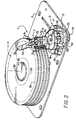
- the rotary actuator disk drive generally designated 1 comprises a base or support plate 3, a disk stack 5 and an actuator 7.
- the disk stack 5 is mounted for rotation at constant speed by a motor (not shown), about an axis 5b of a disk spindle structure 5c secured to the base plate 3.
- a rotary actuator 7 comprises a bearing housing 7a which is rotatably mounted about the spindle 7b which is also secured to the base plate 3. Arms 7c, forming part of an arm stack are mounted upon the bearing housing 7a in axially spaced positions in planes adjacent to the surfaces of the individual disks 5a and, in operation, project between the disks. Load beams 7d, sometimes also referred to as flexures, are individually attached to the free end of each arm 7c at its extremity. Each load beam mounts an individual transducer 7e, such as a magnetic head. Each transducer 7e is disposed in confronting relationship with the adjacent surface of one disk 5a.
- the actuator 7 is rotated about the spindle 7b to move the transducer 7e radially and than to radially position a transducer 7e over the adjacent surface of a disk 5a at a selected track, for track seeking and track following modes of operation, respectively, as is well known, by means of an actuator motor 9.
- This actuator motor 9 comprises a coil structure 9a.
- the coil structure 9a is attached to the bearing housing 7a and the center line of the coil structure is preferably diametrically positioned disposed with respect to the center line of the arms 7c and load beams 7d on the opposite side of the axis of the actuator spindle 7b. In this position the coil structure 9a moves bidirectionally in an arc about the axis of the actuator spindle 7b.
- the coil structure 9a is disposed between a pair of two pole permanent magnets, one above and one below the coil structure 9a. Only one two pole permanent magnet 9b is needed to demonstrate operation. Only the lower permanent magnet is shown in these illustrations in the interest of clarity.
- the lower permanent magnet 9b is disposed upon a steel motor base 9c which is attached to the base plate. Bidirectional movement of the coil structure 9a in its arc in the field of the permanent magnet is achieved, as is well known, by reversibly energizing the coil (not shown) of the coil structure 9a.
- the outer radial limit of angular mechanical movement of the rotary actuator 7 is determined by the crash stop 11.
- the outer radial limit crash stop structure 11 has a crash stop support member 11a secured to the base plate 3.
- a crash stop projection 11b in the form of a flexible arm projecting from the support member 11a, is provided with a latch 11g at its extremity which is engaged with a catch 9d on the outer edge of the coil structure 9a.
- the actuator 7 is mounted upon the base plate 3 by the attachment of the actuator's spindle 7b, which allows actuator rotation about the spindle axes.
- all parts of the actuator 7 are clear of the disk stack 5 and the crash stop structure 11.
- Loading of the transducers 7e upon the disks is accomplished by spreading the transducers apart a distance to clear the thickness of the disk.
- one transducer 7e normally will be positioned on the top surface of a disk and a second transducer 7e will be positioned on a bottom surface of that disk, as is well known.
- the actuator is rotated counter-clockwise in the direction of the arrow, as seen in Fig.
- the transducers 7e are moved across the surface of the disk but out of contact with the surface of the disk.
- the latch 11g on the end of the arm 11b rides up the ramp of the catch 9d.
- the latch 11g moves past the edge of the ramp of the catch 9d and snaps into place, as shown.
- the actuator arm is in its outer radial limit position with the transducer 7e positioned on the disk surface outside of the outer data track 5e.
- the crash stop structure 11 may be made of any suitable material which may be elastically bent or deflected so that the catch 9d on the actuator 7 can clear the latch 11g during assembly and thereafter the latch 11g will return to it's functional crash stop position.
- Suitable crash stop materials include plastics and metals which are sufficiently flexible and resilient for the application.
- the crash stop structure 11 is designed of a structural configuration to provide stiffness or rigidity in the direction of impact forces, resulting from engagement of the confronting faces of the catch 9d and the latch 11g when the actuator moves into its outer radial limit position, but which is sufficiently flexible and resilient in a direction different from the direction in which the impact forces are applied, to permit installation of the actuator 7 onto the base or support plate 3 in a position in which the actuator 7 is clear of the disk stack 5 and the crash stop structure 11, and thereafter permitting movement of the actuator in a counter-clockwise direction, as described, so that the catch 9d moves past the latch 11g, and the latch 11g returns to it's original position so that the outer radial limit crash stop is functional.
- crash stop structure 11 may be fabricated from any material having the described physical characteristics and may be attached to the base or support plate 3 in any suitable manner, a presently preferred fabrication technique, and best mode for practicing the invention, employs outsert casting in which the base or support 3 becomes a part of the mold structure and the crash stop 11 is outsert molded in place on the base or support plate 3, and secured thereto via an opening 11d therethrough.
- Polycarbonate is one of many suitable plastic material for this purpose.
- Fig. 1 serves to provide an easily understood illustration of this invention both as to its principles of operation, and as to its structural design.
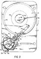
- the limit 5 of angular mechanical movement of the rotary actuator 7 are determined by a crash stop structure 11 having a crash stop support member 11a on the base or support plate 3 and circumferentially spaced crash stop projections, such as the tapered cantilever arms 11b, projecting upwardly from the support member 11a.
- These arms 11b are positioned on opposite sides of a pin 9d which radially projects from the end face of the coil structure 9a between the crash stop arms 11b.
- Engagement of the pin 9d with the respective crash stop arms 11b determines the opposite limits of angular movement of the actuator 7 and, hence, the inner and outer radial mechanical limits of movement of the individual transducers 7e with respect to the adjacent surface of the respective disks.
- the position of the left crash stop arm 11b determines the outermost radial position of the transducer 7e. This position is usually outside of the outermost data track 5e on the surface of the disk.
- the crash stop arm 11b on the right, as seen in Fig. 2 determines the innermost position of the transducer 7e, which is usually between the spindle 5c and the innermost data track 5d on the surface of a disk 5a.
- the crash stop structure 11 has a lower flange 11c on the bottom side of the base or support plate 3, as seen in Fig. 2, which is an integral part of the crash stop structure 11, by means of an integral connection extending through an opening 11d in the base or support plate 3.
- This opening 11d is of any configuration for the purpose of sealing the mounting for positional stabilization and for securing the crash stop structure 11 against linear or angular movement.
- the opening 11d is in a predetermined position at least with respect to the axis of the actuator spindle 7b and preferably with respect to both the disk spindle axis 5b and the axis of the spindle 7b.
- the crash stop structure 11 is fabricated of a plastic material such as polycarbonate which may be outsert molded. Outsert molding techniques are well known and they are not described herein in any detail, but only to the extent that the base or support plate 3 is inserted between the two halves of a mold, the lower half of which has a cavity providing a lower flange 11c and the upper half of which has a cavity corresponding to the particular configuration of the crash stop structure 11.
- a plastic material suitable for this molding operation is polycarbonate which may be glass or carbon filled.
- the cantilever crash stop arms 11b are non-uniformly tapered between their wide bases and their narrower upper ends and are of lesser thickness than of width. The purpose of this is to provide adequate stiffness in the direction of forces resulting from impact of the pin 9d with a confronting edge of a crash stop arm 11b and to provide flexibility in a direction different from the direction of the impact force, so that the outer radial limit crash stop member 11b, on the left as seen in Fig. 2, for example, may be displaced away from the end of the pin 9d, to permit the outer end of the pin 9d to move therepast whenever the transducers 7e are being loaded or unloaded with respect to or on the disk 5a.
- Figs. 4 and 5 Two steps or stages for this assembly operation are seen in Figs. 4 and 5.
- the actuator 7 is installed upon the base or support plate 3 in the first step of the assembly operation, in an angular position in which the actuator is clear of the disk stack 5 and the crash stop structure 11. In this angular position, the pin 9d is located outside of the limits of the crash stop arms 11b.
- the transducers 7e are spaced apart sufficiently to clear the surfaces of the disks 5a.
- the crash stop arm 11b on the left, as seen in Fig. 5, is bent or deflected by applying a force at its upper end in a radially outward direction with respect to the axis of the actuator spindle 7b.
- the crash stop structure 11 may be assembled upon the base plate 3 prior to the time of installation of the actuator eliminating the need for the handling of separate parts and the need for attempting to assemble the crash stop structure 11 on the base plate 3 after the actuator 7 with its delicate transducers 7e has been installed.
- Figs. 6 and 7 illustrate the crash stop structure in greater detail at an enlarged scale.
- a post 11e has been added as part of the outsert molded crash stop structure. This post is used to support other parts not shown of the disk drive.
- This flange 11c is an integral part of the crash stop structure through the elongated opening 11d provided in the base or support plate 3.
- the part 11c1 beneath the base plate 3 has a function beyond that of just a flange and is configured with a depending section 11h provided with a slot 11i which is useful in receiving and supporting a part of a circuit board, for example (not shown).
- Figs. 8 and 9 are illustrations in which Fig. 9 is an elevational view of Fig. 8 taken on line IX-IX associated with Fig. 8.
- the crash stop structure 11 in Figs. 8 and 9 is again a molded part, preferably again of a plastic such as polycarbonate. It is provided with a pin 11f projecting downwardly from the bottom side of the base 11a of the crash stop 11. This is an indexing pin which fits into an opening in the base or support plate 3, and is used to precisely locate the crash stop.
- the crash stop 11 is secured by means of a screw 11g which clears through the support member 11a and threadedly engages the base plate 3 of the disk drive.
- Figs. 6-9 are the same as that discussed in connection with Figs. 2-5.
- these cantilever crash stop arms 11b which function as cantilever beams projecting from the crash stop support member 11a.
- these cantilever crash stop arms 11b are of designed stiffness in the direction of crash stop impact forces, at least that the outer radial limit crash stop arm 11b is flexible in a direction different from that in which the impact forces act.
- the direction as seen in all of these figures is substantially at right angles to the direction in which the impact force acts.
- the crash stop structure 11 can be fabricated of materials other than plastic and can be fabricated by means and techniques other than that involving molding processes.
- a crash stop structure 11 such as seen in Figs. 6-9 is easily fabricated of metal. If fabricated of sheet metal it can be cut or stamped as a flat pattern. The crash stop arms 11b can then be bent to the position shown with respect to the support member 11a. If fabricated of a metal in the annealed or soft state, heat treating thereafter can be employed to provide the flexibility or resilience of the crash stop arms 11b to function properly.
- Such a crash stop structure 11 fabricated of sheet metal is conveniently attached to the disk drive base 3 in the manner illustrated in Figs. 8 and 9. Indexing can be achieved by a shallow stamped depression at the location of the pin 11f in the metal base 11a of the crash stop structure 11, by well known fabrication techniques, during the stamping operation.
- crash stop structure 11 Although particular configurations of the crash stop structure 11 have been illustrated herein, it will be appreciated that other configurations involving the provision of structures providing crash stop surfaces on the actuator 7 different from that of the single pin 9d may be developed.
- the principle of this invention is simply that of providing an outer radial crash stop structure 11 which may be attached to the base plate 3 prior to the time of installation of the actuator, and having an outer radial limit crash stop arm 11b, which is deflectable from crash stop position in a direction different from that in which the crash stop forces act upon that arm 11b, for the purpose of clearing any actuator impact surface or projection 9d on the actuator 7, which cooperates with the outer radial limit crash stop arm 11b, for the purpose of limiting displacement of the actuator 7 in its outer mechanical radial limit.
Landscapes
- Moving Of Heads (AREA)
Claims (7)
- Dispositif d'enregistrement comprenant:· un support (3);· au moins un disque (5a) incluant des enregistrements suivant des pistes espacées radialement (5d, 5e) dans une surface dudit disque (5a);· un moyen (5c) pour monter ledit disque (5a) sur ledit support (3) afin de le faire tourner autour d'un axe (5b);
au moins un transducteur (7e) pour chaque disque (5a);· un moyen actionneur déplaçable (7) sur ledit support (3) pour supporter ledit un transducteur (7e) de façon adjacente à ladite surface dudit disque (5a) afin d'obtenir un déplacement en des positions radiales différentes (5d, 5e) sur ledit disque (5a);· un moyen moteur (9) pour déplacer ledit moyen d'actionneur (7) entre des limites de positions radiales interne (5d) et externe (5e);· une structure de butée de sécurité (11) sur ledit support (3);· une protubérance de butée de sécurité (11b) sur ladite structure de butée de sécurité (11) dans le trajet de déplacement dudit moyen actionneur (7) afin de coopérer avec ledit moyen actionneur (7) dans sa limite de position radiale externe (5e);caractérisé par le fait que ladite protubérance de butée de sécurité (11b) est mécaniquement rigide suivant la direction des forces d'impact entre ledit moyen actionneur (7) et ladite protubérance de butée de sécurité (11b) et est déplaçable par rapport à une position de butée de sécurité, tout en étant poussée en direction de celle-ci, suivant une direction différente de la direction desdites forces de butée de sécurité, afin de permettre un déplacement de ladite protubérance de butée de sécurité (11b) par rapport à la position de butée de sécurité de telle sorte que ledit moyen actionneur (7) puisse se déplacer au-delà. - Dispositif d'enregistrement selon la revendication 1, dans lequel:
ladite protubérance de butée de sécurité (11b) fait partie intégrante de ladite structure de butée de sécurité (11) et est flexible suivant ladite direction différente de telle sorte qu'elle puisse être déviée par rapport à ladite position de butée de sécurité . - Dispositif d'enregistrement selon les revendications 1 ou 2, dans lequel:
ladite protubérance de butée de sécurité (11b) comprend un bras (11b) qui est flexible suivant ladite direction différente. - Dispositif d'enregistrement selon les revendications 1 ou 2, dans lequel:
ladite protubérance de butée de sécurité comprend un bras monté en porte-à-faux (11b) qui fait saillie depuis ladite structure de butée de sécurité (11), ledit bras en porte-à-faux (11b) étant flexible et pouvant se dévier suivant ladite direction différente par rapport à la position de butée de sécurité. - Dispositif d'enregistrement selon la revendication 4, dans lequel:
ledit bras en porte-à-faux (11b) présente une dimension en coupe transversale présentant une largeur suivant la direction desdites forces d'impact supérieure à l'épaisseur dudit bras, de façon à conférer une rigidité de butée de sécurité suivant la direction desdites forces d'impact et une flexibilité suivant ladite direction différente. - Dispositif d'enregistrement selon les revendications 4 ou 5, dans lequel:· ledit bras en porte-à-faux (11b) de la structure de butée de sécurité fait saillie par rapport audit élément suivant une direction le long de la voie de déplacement dudit moyen actionneur (7), et ce bras en porte-à-faux comprend en outre:· un verrouillage (11g) sur ledit bras en porte-à-faux (11b) déplacé par rapport audit élément; et· un crochet (9d) sur ledit moyen actionneur (7) destiné à s'accrocher avec ledit élément de verrouillage (11g) lorsque ledit moyen actionneur (7) est dans sa limite radiale mécanique externe.
- Dispositif d'enregistrement selon l'une quelconque des revendications précédentes, dans lequel:
ledit déplacement de ladite protubérance de butée de sécurité (11b) est essentiellement élastique.
Applications Claiming Priority (2)
| Application Number | Priority Date | Filing Date | Title |
|---|---|---|---|
| US532470 | 1990-06-01 | ||
| US07/532,470 US5134608A (en) | 1990-06-01 | 1990-06-01 | Disk drive crash stop |
Publications (3)
| Publication Number | Publication Date |
|---|---|
| EP0463336A2 EP0463336A2 (fr) | 1992-01-02 |
| EP0463336A3 EP0463336A3 (en) | 1992-06-03 |
| EP0463336B1 true EP0463336B1 (fr) | 1995-11-29 |
Family
ID=24121954
Family Applications (1)
| Application Number | Title | Priority Date | Filing Date |
|---|---|---|---|
| EP91107507A Expired - Lifetime EP0463336B1 (fr) | 1990-06-01 | 1991-05-08 | Dispositif d'arrêt de tamponnage pour entraînement de disque |
Country Status (4)
| Country | Link |
|---|---|
| US (1) | US5134608A (fr) |
| EP (1) | EP0463336B1 (fr) |
| JP (1) | JPH04263175A (fr) |
| DE (1) | DE69114919T2 (fr) |
Families Citing this family (35)
| Publication number | Priority date | Publication date | Assignee | Title |
|---|---|---|---|---|
| US5956213A (en) | 1988-01-25 | 1999-09-21 | Seagate Technology, Inc. | Latch mechanism for disk drive using magnetic field of actuator magnets |
| US6600631B1 (en) * | 1989-11-27 | 2003-07-29 | Censtor Corp. | Transducer/flexure/conductor structure for electromagnetic read/write system |
| US5262913A (en) * | 1990-11-09 | 1993-11-16 | Seagate Technology, Inc. | Easily adjustable crash stop for a disc drive |
| US5365389A (en) * | 1990-11-09 | 1994-11-15 | Seagate Technology, Inc. | Crash stop and magnetic latch for optimum use of disc space |
| US5404257A (en) * | 1990-12-19 | 1995-04-04 | Integral Peripherals, Inc. | Rotary inertial latch for disk drive actuator |
| US5296986A (en) * | 1990-12-19 | 1994-03-22 | Integral Peripherals, Inc. | Rotary intertial latch for disk drive actuator to protect against rotational shock force |
| US5379171A (en) * | 1991-09-25 | 1995-01-03 | Integral Peripherals | Microminiature hard disk drive |
| US6310747B1 (en) | 1991-09-25 | 2001-10-30 | Mobile Storage Technology, Inc. | Method for reducing external signal interference with signals in a computer disk storage system |
| WO1993010531A1 (fr) * | 1991-11-22 | 1993-05-27 | Conner Peripherals, Inc. | Moteur de bobine mobile a couple constant et petite dimension |
| US5477403A (en) * | 1992-01-24 | 1995-12-19 | Hewlett-Packard Company | Disk drive having a crash stop detent actuator latch |
| US5262912A (en) * | 1992-06-05 | 1993-11-16 | Seagate Technology, Inc. | Limit stop and limit stop incorporating a flux concentrator latch for disc drives |
| JPH05342778A (ja) * | 1992-06-05 | 1993-12-24 | Nec Corp | ヘッド支持アームのハウジング及びこれを用いたヘッド・ディスク組立体 |
| US5313354A (en) * | 1992-11-12 | 1994-05-17 | Seagate Technology, Inc. | Disc drive latch housing having improved vibration dampening |
| US5343346A (en) * | 1993-05-06 | 1994-08-30 | Xolox Corporation | Single point magnetic contact hatch assembly |
| US5455726A (en) * | 1993-10-07 | 1995-10-03 | Micropolis Corporation | Versatile head positioner stop |
| US5448436A (en) * | 1994-03-14 | 1995-09-05 | International Business Machines Corporation | Disk drive with shock-resistant rotary actuator |
| US5600516A (en) * | 1994-03-17 | 1997-02-04 | Seagate Technology, Inc. | Deflectable crash stop in actuator arm assembly overmold |
| US5731933A (en) * | 1994-10-18 | 1998-03-24 | Iomega Corporation | Molded actuator crash stops |
| JPH08180615A (ja) * | 1994-12-28 | 1996-07-12 | Fujitsu Ltd | 磁気ディスク装置 |
| JP3134986B2 (ja) * | 1996-11-27 | 2001-02-13 | 船井電機株式会社 | シャーシ用部品係止装置 |
| US5864449A (en) * | 1997-08-22 | 1999-01-26 | International Business Machines Corporation | Precision limit stop for high density disk drives |
| KR100288287B1 (ko) | 1997-09-03 | 2001-05-02 | 윤종용 | 하드디스크드라이브의액츄에이터고정장치 |
| KR19990056326A (ko) * | 1997-12-29 | 1999-07-15 | 윤종용 | 하드디스크 드라이브의 자기헤드 이송장치 |
| US6125017A (en) * | 1998-03-20 | 2000-09-26 | Seagate Technology, Inc. | Actuator crash stops providing a two-stage braking impulse |
| US6426847B1 (en) * | 1999-04-21 | 2002-07-30 | Seagate Technology Llc | Over-molded base plate and method of manufacture of over-molded base plate for a disc drive |
| US6542335B1 (en) | 1999-05-12 | 2003-04-01 | Seagate Technology Llc | Inertial spring latch assembly and compressive limit stop in a disc drive |
| US6597144B2 (en) | 2000-06-21 | 2003-07-22 | Whirlpool Corporation | Method and apparatus for power loss detection and saving of operation settings in an appliance |
| US6680823B2 (en) | 2001-01-18 | 2004-01-20 | Seagate Technology Llc | Moveable outer stop |
| US6543124B2 (en) | 2001-01-18 | 2003-04-08 | Seagate Technology Llc | Voice coil motor attachment for a hard disc assembly |
| US6744604B2 (en) | 2001-03-21 | 2004-06-01 | Seagate Technology Llc | Low particulating latch for a disc drive |
| SG116469A1 (en) * | 2002-05-03 | 2005-11-28 | Seagate Technology Llc | Overmolded crash stop for a disc drive. |
| US7274530B2 (en) * | 2003-10-09 | 2007-09-25 | Seagate Technology Llc | Logical mapping for improved head switching between corresponding tracks in a data handling device |
| US7733610B2 (en) * | 2006-02-10 | 2010-06-08 | Seagate Technology Llc | Load/unload ramp for an actuator assembly in a data storage device |
| US8451564B2 (en) | 2010-12-27 | 2013-05-28 | HGST Netherlands B.V. | Impact energy dispersing crash stop for a hard disk drive |
| CN102800329B (zh) * | 2011-05-27 | 2016-08-03 | 新科实业有限公司 | 音圈马达及具有该音圈马达的磁盘驱动单元 |
Family Cites Families (9)
| Publication number | Priority date | Publication date | Assignee | Title |
|---|---|---|---|---|
| JPS5979470A (ja) * | 1982-10-29 | 1984-05-08 | Toshiba Corp | 磁気デイスク装置のキヤリツジロツク機構 |
| US4635151A (en) * | 1985-01-25 | 1987-01-06 | Priam Corporation | Rotary actuator having preloaded spring crash stop |
| JPH0743901B2 (ja) * | 1985-11-30 | 1995-05-15 | 株式会社東芝 | 磁気記録再生装置のキヤリツジロツク機構 |
| US4716482A (en) * | 1986-02-14 | 1987-12-29 | Hewlett-Packard Company | Head actuator limit stop assembly for a disk memory drive |
| US4845579A (en) * | 1987-10-30 | 1989-07-04 | Seagate Technology, Inc. | Disc drive incorporating automatic wear compensation for a pivoted arm |
| JPH0197463U (fr) * | 1987-12-22 | 1989-06-28 | ||
| US4965684A (en) * | 1988-01-25 | 1990-10-23 | Conner Peripherals, Inc. | Low height disk drive |
| US4890176A (en) * | 1988-07-18 | 1989-12-26 | Seagate Technology, Inc. | Crash stop and magnetic latch for a voice coil actuator |
| US4939611A (en) * | 1988-10-20 | 1990-07-03 | Hewlett-Packard Company | Vertical displacement limit stop in a disk drive for preventing disk surface damage |
-
1990
- 1990-06-01 US US07/532,470 patent/US5134608A/en not_active Expired - Fee Related
-
1991
- 1991-05-08 EP EP91107507A patent/EP0463336B1/fr not_active Expired - Lifetime
- 1991-05-08 DE DE69114919T patent/DE69114919T2/de not_active Expired - Fee Related
- 1991-05-31 JP JP3157807A patent/JPH04263175A/ja active Pending
Also Published As
| Publication number | Publication date |
|---|---|
| DE69114919T2 (de) | 1996-04-18 |
| EP0463336A3 (en) | 1992-06-03 |
| US5134608A (en) | 1992-07-28 |
| JPH04263175A (ja) | 1992-09-18 |
| EP0463336A2 (fr) | 1992-01-02 |
| DE69114919D1 (de) | 1996-01-11 |
Similar Documents
| Publication | Publication Date | Title |
|---|---|---|
| US5134608A (en) | Disk drive crash stop | |
| US4939611A (en) | Vertical displacement limit stop in a disk drive for preventing disk surface damage | |
| US5365389A (en) | Crash stop and magnetic latch for optimum use of disc space | |
| EP0473719B1 (fr) | Loquet magnetique pour actuateur d'unite de disques | |
| US6452753B1 (en) | Universal load/unload ramp | |
| US6185074B1 (en) | Inertial latch having an interposer that prevents the head from leaving the ramp load during a shock event | |
| US5187627A (en) | Magnetic latch and crash stop | |
| KR100372994B1 (ko) | 로드 및 언로드 기구를 갖춘 자기 디스크 장치 | |
| JPH06259898A (ja) | ロータリーディスク駆動アクチュエーター | |
| WO2001015165A1 (fr) | Amortisseur de choc du bras de lecture | |
| US5012371A (en) | Disk drive crash stop/actuator latch | |
| KR19990044155A (ko) | 크래쉬 스톱 에어록 기구 | |
| JP2000509876A (ja) | 改善された衝撃耐性を備えるアクチュエータラッチ | |
| CA2204567A1 (fr) | Systeme de verrouillage d'un lecteur de disque a l'epreuve des forces de rotation | |
| KR100277074B1 (ko) | 디스크 드라이브용 헤드구속장치 및 방법 | |
| US6775106B1 (en) | E-block having improved resonance characteristics and improved fragility | |
| EP0459191B1 (fr) | Dispositif d'enregistrement de disques et son procédé de fabrication | |
| JPH06124556A (ja) | 磁気ディスク駆動装置 | |
| US6091579A (en) | Memory device with improved mechanisms to position a yoke | |
| US7016157B1 (en) | E-block having improved resonance characteristics and improved fragility | |
| KR20030077983A (ko) | 재생-기록 헤드의 트랙 포지셔닝 에러를 감소시키기 위한램프 설계 | |
| US6731469B2 (en) | Integral inertial latch design | |
| US20030039076A1 (en) | Crash stop assembly in a disc drive | |
| JP2850915B2 (ja) | 磁気ディスク装置のキャリッジストッパ構造 | |
| US20050286173A1 (en) | Stop with adjustable stiffness |
Legal Events
| Date | Code | Title | Description |
|---|---|---|---|
| PUAI | Public reference made under article 153(3) epc to a published international application that has entered the european phase |
Free format text: ORIGINAL CODE: 0009012 |
|
| AK | Designated contracting states |
Kind code of ref document: A2 Designated state(s): DE FR GB |
|
| PUAL | Search report despatched |
Free format text: ORIGINAL CODE: 0009013 |
|
| AK | Designated contracting states |
Kind code of ref document: A3 Designated state(s): DE FR GB |
|
| 17P | Request for examination filed |
Effective date: 19921203 |
|
| 17Q | First examination report despatched |
Effective date: 19941123 |
|
| GRAA | (expected) grant |
Free format text: ORIGINAL CODE: 0009210 |
|
| AK | Designated contracting states |
Kind code of ref document: B1 Designated state(s): DE FR GB |
|
| REF | Corresponds to: |
Ref document number: 69114919 Country of ref document: DE Date of ref document: 19960111 |
|
| ET | Fr: translation filed | ||
| PGFP | Annual fee paid to national office [announced via postgrant information from national office to epo] |
Ref country code: FR Payment date: 19960415 Year of fee payment: 6 |
|
| PGFP | Annual fee paid to national office [announced via postgrant information from national office to epo] |
Ref country code: DE Payment date: 19960423 Year of fee payment: 6 |
|
| PGFP | Annual fee paid to national office [announced via postgrant information from national office to epo] |
Ref country code: GB Payment date: 19960425 Year of fee payment: 6 |
|
| PLBE | No opposition filed within time limit |
Free format text: ORIGINAL CODE: 0009261 |
|
| STAA | Information on the status of an ep patent application or granted ep patent |
Free format text: STATUS: NO OPPOSITION FILED WITHIN TIME LIMIT |
|
| 26N | No opposition filed | ||
| PG25 | Lapsed in a contracting state [announced via postgrant information from national office to epo] |
Ref country code: GB Effective date: 19970508 |
|
| GBPC | Gb: european patent ceased through non-payment of renewal fee |
Effective date: 19970508 |
|
| PG25 | Lapsed in a contracting state [announced via postgrant information from national office to epo] |
Ref country code: FR Free format text: LAPSE BECAUSE OF NON-PAYMENT OF DUE FEES Effective date: 19980130 |
|
| PG25 | Lapsed in a contracting state [announced via postgrant information from national office to epo] |
Ref country code: DE Free format text: LAPSE BECAUSE OF NON-PAYMENT OF DUE FEES Effective date: 19980203 |
|
| REG | Reference to a national code |
Ref country code: FR Ref legal event code: ST |