EP0463382A2 - Verfahren zur Herstellung von doppelseitigen magneto-optischen Platten mit verminderter Doppelbrechung - Google Patents
Verfahren zur Herstellung von doppelseitigen magneto-optischen Platten mit verminderter Doppelbrechung Download PDFInfo
- Publication number
- EP0463382A2 EP0463382A2 EP91108525A EP91108525A EP0463382A2 EP 0463382 A2 EP0463382 A2 EP 0463382A2 EP 91108525 A EP91108525 A EP 91108525A EP 91108525 A EP91108525 A EP 91108525A EP 0463382 A2 EP0463382 A2 EP 0463382A2
- Authority
- EP
- European Patent Office
- Prior art keywords
- disks
- adhesive
- recording
- sided
- information area
- Prior art date
- Legal status (The legal status is an assumption and is not a legal conclusion. Google has not performed a legal analysis and makes no representation as to the accuracy of the status listed.)
- Withdrawn
Links
- 238000004519 manufacturing process Methods 0.000 title description 3
- 239000000853 adhesive Substances 0.000 claims abstract description 55
- 230000001070 adhesive effect Effects 0.000 claims abstract description 55
- 239000010410 layer Substances 0.000 claims description 38
- 238000000034 method Methods 0.000 claims description 28
- 239000000758 substrate Substances 0.000 claims description 18
- 239000012790 adhesive layer Substances 0.000 claims description 14
- 239000000463 material Substances 0.000 claims description 14
- 230000002093 peripheral effect Effects 0.000 claims description 13
- 230000003287 optical effect Effects 0.000 claims description 11
- 239000004831 Hot glue Substances 0.000 claims description 7
- 238000010030 laminating Methods 0.000 claims description 7
- 230000004888 barrier function Effects 0.000 claims description 5
- 238000003475 lamination Methods 0.000 claims description 3
- 239000011253 protective coating Substances 0.000 claims 2
- 239000004820 Pressure-sensitive adhesive Substances 0.000 claims 1
- 230000008569 process Effects 0.000 description 9
- 238000003825 pressing Methods 0.000 description 7
- 239000010408 film Substances 0.000 description 6
- 230000010287 polarization Effects 0.000 description 6
- 239000013598 vector Substances 0.000 description 5
- 229920002799 BoPET Polymers 0.000 description 4
- 230000005415 magnetization Effects 0.000 description 4
- 239000004033 plastic Substances 0.000 description 4
- 229920003023 plastic Polymers 0.000 description 4
- 239000002390 adhesive tape Substances 0.000 description 3
- 230000008859 change Effects 0.000 description 3
- 238000010586 diagram Methods 0.000 description 3
- 229910052751 metal Inorganic materials 0.000 description 3
- 239000002184 metal Substances 0.000 description 3
- -1 polypropylene Polymers 0.000 description 3
- 239000011241 protective layer Substances 0.000 description 3
- 238000010561 standard procedure Methods 0.000 description 3
- 238000000576 coating method Methods 0.000 description 2
- 239000002131 composite material Substances 0.000 description 2
- 238000010276 construction Methods 0.000 description 2
- 230000000694 effects Effects 0.000 description 2
- 239000004417 polycarbonate Substances 0.000 description 2
- 229920000515 polycarbonate Polymers 0.000 description 2
- 229920000728 polyester Polymers 0.000 description 2
- 238000002310 reflectometry Methods 0.000 description 2
- 239000002904 solvent Substances 0.000 description 2
- VEXZGXHMUGYJMC-UHFFFAOYSA-M Chloride anion Chemical compound [Cl-] VEXZGXHMUGYJMC-UHFFFAOYSA-M 0.000 description 1
- VYZAMTAEIAYCRO-UHFFFAOYSA-N Chromium Chemical compound [Cr] VYZAMTAEIAYCRO-UHFFFAOYSA-N 0.000 description 1
- 239000004821 Contact adhesive Substances 0.000 description 1
- 239000004593 Epoxy Substances 0.000 description 1
- JOYRKODLDBILNP-UHFFFAOYSA-N Ethyl urethane Chemical compound CCOC(N)=O JOYRKODLDBILNP-UHFFFAOYSA-N 0.000 description 1
- IAYPIBMASNFSPL-UHFFFAOYSA-N Ethylene oxide Chemical group C1CO1 IAYPIBMASNFSPL-UHFFFAOYSA-N 0.000 description 1
- 239000013032 Hydrocarbon resin Substances 0.000 description 1
- 230000005374 Kerr effect Effects 0.000 description 1
- 239000005041 Mylar™ Substances 0.000 description 1
- 239000004698 Polyethylene Substances 0.000 description 1
- 239000004743 Polypropylene Substances 0.000 description 1
- RTAQQCXQSZGOHL-UHFFFAOYSA-N Titanium Chemical compound [Ti] RTAQQCXQSZGOHL-UHFFFAOYSA-N 0.000 description 1
- 239000011358 absorbing material Substances 0.000 description 1
- NIXOWILDQLNWCW-UHFFFAOYSA-N acrylic acid group Chemical group C(C=C)(=O)O NIXOWILDQLNWCW-UHFFFAOYSA-N 0.000 description 1
- 125000001931 aliphatic group Chemical group 0.000 description 1
- 229910052782 aluminium Inorganic materials 0.000 description 1
- XAGFODPZIPBFFR-UHFFFAOYSA-N aluminium Chemical compound [Al] XAGFODPZIPBFFR-UHFFFAOYSA-N 0.000 description 1
- 238000010420 art technique Methods 0.000 description 1
- 230000015572 biosynthetic process Effects 0.000 description 1
- 229920001400 block copolymer Polymers 0.000 description 1
- 229910052804 chromium Inorganic materials 0.000 description 1
- 239000011651 chromium Substances 0.000 description 1
- 239000011248 coating agent Substances 0.000 description 1
- 230000001427 coherent effect Effects 0.000 description 1
- 230000006835 compression Effects 0.000 description 1
- 238000007906 compression Methods 0.000 description 1
- 239000000356 contaminant Substances 0.000 description 1
- 238000007796 conventional method Methods 0.000 description 1
- 230000007797 corrosion Effects 0.000 description 1
- 238000005260 corrosion Methods 0.000 description 1
- 230000008878 coupling Effects 0.000 description 1
- 238000010168 coupling process Methods 0.000 description 1
- 238000005859 coupling reaction Methods 0.000 description 1
- 238000013500 data storage Methods 0.000 description 1
- 230000003247 decreasing effect Effects 0.000 description 1
- 230000007547 defect Effects 0.000 description 1
- 150000004985 diamines Chemical class 0.000 description 1
- 235000014113 dietary fatty acids Nutrition 0.000 description 1
- 229920001971 elastomer Polymers 0.000 description 1
- 238000005516 engineering process Methods 0.000 description 1
- 238000011156 evaluation Methods 0.000 description 1
- 230000003203 everyday effect Effects 0.000 description 1
- 230000001747 exhibiting effect Effects 0.000 description 1
- 229930195729 fatty acid Natural products 0.000 description 1
- 239000000194 fatty acid Substances 0.000 description 1
- 150000004665 fatty acids Chemical class 0.000 description 1
- 239000011521 glass Substances 0.000 description 1
- 239000012761 high-performance material Substances 0.000 description 1
- 239000012943 hotmelt Substances 0.000 description 1
- 229920006270 hydrocarbon resin Polymers 0.000 description 1
- 150000002500 ions Chemical class 0.000 description 1
- 230000007246 mechanism Effects 0.000 description 1
- 229910052753 mercury Inorganic materials 0.000 description 1
- 239000000203 mixture Substances 0.000 description 1
- 150000004767 nitrides Chemical class 0.000 description 1
- 239000002245 particle Substances 0.000 description 1
- 229920006267 polyester film Polymers 0.000 description 1
- 229920000573 polyethylene Polymers 0.000 description 1
- 229920000307 polymer substrate Polymers 0.000 description 1
- 229920001155 polypropylene Polymers 0.000 description 1
- 238000012545 processing Methods 0.000 description 1
- 230000001681 protective effect Effects 0.000 description 1
- 238000011160 research Methods 0.000 description 1
- 238000012827 research and development Methods 0.000 description 1
- 229920005989 resin Polymers 0.000 description 1
- 239000011347 resin Substances 0.000 description 1
- 230000004044 response Effects 0.000 description 1
- 239000005060 rubber Substances 0.000 description 1
- 230000035945 sensitivity Effects 0.000 description 1
- 239000013464 silicone adhesive Substances 0.000 description 1
- 239000007787 solid Substances 0.000 description 1
- 238000003860 storage Methods 0.000 description 1
- 230000003746 surface roughness Effects 0.000 description 1
- 229920001169 thermoplastic Polymers 0.000 description 1
- 229920006345 thermoplastic polyamide Polymers 0.000 description 1
- 229920001187 thermosetting polymer Polymers 0.000 description 1
- 239000004416 thermosoftening plastic Substances 0.000 description 1
- 239000010409 thin film Substances 0.000 description 1
- 239000010936 titanium Substances 0.000 description 1
- 229910052719 titanium Inorganic materials 0.000 description 1
Images


Classifications
-
- G—PHYSICS
- G11—INFORMATION STORAGE
- G11B—INFORMATION STORAGE BASED ON RELATIVE MOVEMENT BETWEEN RECORD CARRIER AND TRANSDUCER
- G11B11/00—Recording on or reproducing from the same record carrier wherein for these two operations the methods are covered by different main groups of groups G11B3/00 - G11B7/00 or by different subgroups of group G11B9/00; Record carriers therefor
- G11B11/10—Recording on or reproducing from the same record carrier wherein for these two operations the methods are covered by different main groups of groups G11B3/00 - G11B7/00 or by different subgroups of group G11B9/00; Record carriers therefor using recording by magnetic means or other means for magnetisation or demagnetisation of a record carrier, e.g. light induced spin magnetisation; Demagnetisation by thermal or stress means in the presence or not of an orienting magnetic field
- G11B11/105—Recording on or reproducing from the same record carrier wherein for these two operations the methods are covered by different main groups of groups G11B3/00 - G11B7/00 or by different subgroups of group G11B9/00; Record carriers therefor using recording by magnetic means or other means for magnetisation or demagnetisation of a record carrier, e.g. light induced spin magnetisation; Demagnetisation by thermal or stress means in the presence or not of an orienting magnetic field using a beam of light or a magnetic field for recording by change of magnetisation and a beam of light for reproducing, i.e. magneto-optical, e.g. light-induced thermomagnetic recording, spin magnetisation recording, Kerr or Faraday effect reproducing
- G11B11/10582—Record carriers characterised by the selection of the material or by the structure or form
-
- B—PERFORMING OPERATIONS; TRANSPORTING
- B29—WORKING OF PLASTICS; WORKING OF SUBSTANCES IN A PLASTIC STATE IN GENERAL
- B29C—SHAPING OR JOINING OF PLASTICS; SHAPING OF MATERIAL IN A PLASTIC STATE, NOT OTHERWISE PROVIDED FOR; AFTER-TREATMENT OF THE SHAPED PRODUCTS, e.g. REPAIRING
- B29C65/00—Joining or sealing of preformed parts, e.g. welding of plastics materials; Apparatus therefor
- B29C65/48—Joining or sealing of preformed parts, e.g. welding of plastics materials; Apparatus therefor using adhesives, i.e. using supplementary joining material; solvent bonding
- B29C65/50—Joining or sealing of preformed parts, e.g. welding of plastics materials; Apparatus therefor using adhesives, i.e. using supplementary joining material; solvent bonding using adhesive tape, e.g. thermoplastic tape; using threads or the like
-
- B—PERFORMING OPERATIONS; TRANSPORTING
- B29—WORKING OF PLASTICS; WORKING OF SUBSTANCES IN A PLASTIC STATE IN GENERAL
- B29C—SHAPING OR JOINING OF PLASTICS; SHAPING OF MATERIAL IN A PLASTIC STATE, NOT OTHERWISE PROVIDED FOR; AFTER-TREATMENT OF THE SHAPED PRODUCTS, e.g. REPAIRING
- B29C65/00—Joining or sealing of preformed parts, e.g. welding of plastics materials; Apparatus therefor
- B29C65/78—Means for handling the parts to be joined, e.g. for making containers or hollow articles, e.g. means for handling sheets, plates, web-like materials, tubular articles, hollow articles or elements to be joined therewith; Means for discharging the joined articles from the joining apparatus
- B29C65/7802—Positioning the parts to be joined, e.g. aligning, indexing or centring
- B29C65/7805—Positioning the parts to be joined, e.g. aligning, indexing or centring the parts to be joined comprising positioning features
- B29C65/7808—Positioning the parts to be joined, e.g. aligning, indexing or centring the parts to be joined comprising positioning features in the form of holes or slots
- B29C65/7811—Positioning the parts to be joined, e.g. aligning, indexing or centring the parts to be joined comprising positioning features in the form of holes or slots for centring purposes
-
- B—PERFORMING OPERATIONS; TRANSPORTING
- B29—WORKING OF PLASTICS; WORKING OF SUBSTANCES IN A PLASTIC STATE IN GENERAL
- B29C—SHAPING OR JOINING OF PLASTICS; SHAPING OF MATERIAL IN A PLASTIC STATE, NOT OTHERWISE PROVIDED FOR; AFTER-TREATMENT OF THE SHAPED PRODUCTS, e.g. REPAIRING
- B29C66/00—General aspects of processes or apparatus for joining preformed parts
- B29C66/01—General aspects dealing with the joint area or with the area to be joined
- B29C66/05—Particular design of joint configurations
- B29C66/10—Particular design of joint configurations particular design of the joint cross-sections
- B29C66/11—Joint cross-sections comprising a single joint-segment, i.e. one of the parts to be joined comprising a single joint-segment in the joint cross-section
- B29C66/112—Single lapped joints
- B29C66/1122—Single lap to lap joints, i.e. overlap joints
-
- B—PERFORMING OPERATIONS; TRANSPORTING
- B29—WORKING OF PLASTICS; WORKING OF SUBSTANCES IN A PLASTIC STATE IN GENERAL
- B29C—SHAPING OR JOINING OF PLASTICS; SHAPING OF MATERIAL IN A PLASTIC STATE, NOT OTHERWISE PROVIDED FOR; AFTER-TREATMENT OF THE SHAPED PRODUCTS, e.g. REPAIRING
- B29C66/00—General aspects of processes or apparatus for joining preformed parts
- B29C66/40—General aspects of joining substantially flat articles, e.g. plates, sheets or web-like materials; Making flat seams in tubular or hollow articles; Joining single elements to substantially flat surfaces
- B29C66/41—Joining substantially flat articles ; Making flat seams in tubular or hollow articles
- B29C66/45—Joining of substantially the whole surface of the articles
- B29C66/452—Joining of substantially the whole surface of the articles the article having a disc form, e.g. making CDs or DVDs
-
- B—PERFORMING OPERATIONS; TRANSPORTING
- B29—WORKING OF PLASTICS; WORKING OF SUBSTANCES IN A PLASTIC STATE IN GENERAL
- B29C—SHAPING OR JOINING OF PLASTICS; SHAPING OF MATERIAL IN A PLASTIC STATE, NOT OTHERWISE PROVIDED FOR; AFTER-TREATMENT OF THE SHAPED PRODUCTS, e.g. REPAIRING
- B29C66/00—General aspects of processes or apparatus for joining preformed parts
- B29C66/80—General aspects of machine operations or constructions and parts thereof
- B29C66/82—Pressure application arrangements, e.g. transmission or actuating mechanisms for joining tools or clamps
- B29C66/826—Pressure application arrangements, e.g. transmission or actuating mechanisms for joining tools or clamps without using a separate pressure application tool, e.g. the own weight of the parts to be joined
- B29C66/8266—Pressure application arrangements, e.g. transmission or actuating mechanisms for joining tools or clamps without using a separate pressure application tool, e.g. the own weight of the parts to be joined using fluid pressure directly acting on the parts to be joined
- B29C66/82661—Pressure application arrangements, e.g. transmission or actuating mechanisms for joining tools or clamps without using a separate pressure application tool, e.g. the own weight of the parts to be joined using fluid pressure directly acting on the parts to be joined by means of vacuum
-
- B—PERFORMING OPERATIONS; TRANSPORTING
- B29—WORKING OF PLASTICS; WORKING OF SUBSTANCES IN A PLASTIC STATE IN GENERAL
- B29C—SHAPING OR JOINING OF PLASTICS; SHAPING OF MATERIAL IN A PLASTIC STATE, NOT OTHERWISE PROVIDED FOR; AFTER-TREATMENT OF THE SHAPED PRODUCTS, e.g. REPAIRING
- B29C66/00—General aspects of processes or apparatus for joining preformed parts
- B29C66/80—General aspects of machine operations or constructions and parts thereof
- B29C66/83—General aspects of machine operations or constructions and parts thereof characterised by the movement of the joining or pressing tools
- B29C66/832—Reciprocating joining or pressing tools
- B29C66/8322—Joining or pressing tools reciprocating along one axis
-
- B—PERFORMING OPERATIONS; TRANSPORTING
- B29—WORKING OF PLASTICS; WORKING OF SUBSTANCES IN A PLASTIC STATE IN GENERAL
- B29C—SHAPING OR JOINING OF PLASTICS; SHAPING OF MATERIAL IN A PLASTIC STATE, NOT OTHERWISE PROVIDED FOR; AFTER-TREATMENT OF THE SHAPED PRODUCTS, e.g. REPAIRING
- B29C65/00—Joining or sealing of preformed parts, e.g. welding of plastics materials; Apparatus therefor
- B29C65/48—Joining or sealing of preformed parts, e.g. welding of plastics materials; Apparatus therefor using adhesives, i.e. using supplementary joining material; solvent bonding
- B29C65/4805—Joining or sealing of preformed parts, e.g. welding of plastics materials; Apparatus therefor using adhesives, i.e. using supplementary joining material; solvent bonding characterised by the type of adhesives
- B29C65/481—Non-reactive adhesives, e.g. physically hardening adhesives
- B29C65/4815—Hot melt adhesives, e.g. thermoplastic adhesives
-
- B—PERFORMING OPERATIONS; TRANSPORTING
- B29—WORKING OF PLASTICS; WORKING OF SUBSTANCES IN A PLASTIC STATE IN GENERAL
- B29C—SHAPING OR JOINING OF PLASTICS; SHAPING OF MATERIAL IN A PLASTIC STATE, NOT OTHERWISE PROVIDED FOR; AFTER-TREATMENT OF THE SHAPED PRODUCTS, e.g. REPAIRING
- B29C65/00—Joining or sealing of preformed parts, e.g. welding of plastics materials; Apparatus therefor
- B29C65/48—Joining or sealing of preformed parts, e.g. welding of plastics materials; Apparatus therefor using adhesives, i.e. using supplementary joining material; solvent bonding
- B29C65/4805—Joining or sealing of preformed parts, e.g. welding of plastics materials; Apparatus therefor using adhesives, i.e. using supplementary joining material; solvent bonding characterised by the type of adhesives
- B29C65/481—Non-reactive adhesives, e.g. physically hardening adhesives
- B29C65/4825—Pressure sensitive adhesives
-
- B—PERFORMING OPERATIONS; TRANSPORTING
- B29—WORKING OF PLASTICS; WORKING OF SUBSTANCES IN A PLASTIC STATE IN GENERAL
- B29C—SHAPING OR JOINING OF PLASTICS; SHAPING OF MATERIAL IN A PLASTIC STATE, NOT OTHERWISE PROVIDED FOR; AFTER-TREATMENT OF THE SHAPED PRODUCTS, e.g. REPAIRING
- B29C66/00—General aspects of processes or apparatus for joining preformed parts
- B29C66/70—General aspects of processes or apparatus for joining preformed parts characterised by the composition, physical properties or the structure of the material of the parts to be joined; Joining with non-plastics material
- B29C66/71—General aspects of processes or apparatus for joining preformed parts characterised by the composition, physical properties or the structure of the material of the parts to be joined; Joining with non-plastics material characterised by the composition of the plastics material of the parts to be joined
-
- B—PERFORMING OPERATIONS; TRANSPORTING
- B29—WORKING OF PLASTICS; WORKING OF SUBSTANCES IN A PLASTIC STATE IN GENERAL
- B29K—INDEXING SCHEME ASSOCIATED WITH SUBCLASSES B29B, B29C OR B29D, RELATING TO MOULDING MATERIALS OR TO MATERIALS FOR MOULDS, REINFORCEMENTS, FILLERS OR PREFORMED PARTS, e.g. INSERTS
- B29K2995/00—Properties of moulding materials, reinforcements, fillers, preformed parts or moulds
- B29K2995/0018—Properties of moulding materials, reinforcements, fillers, preformed parts or moulds having particular optical properties, e.g. fluorescent or phosphorescent
- B29K2995/0031—Refractive
- B29K2995/0032—Birefringent
-
- B—PERFORMING OPERATIONS; TRANSPORTING
- B29—WORKING OF PLASTICS; WORKING OF SUBSTANCES IN A PLASTIC STATE IN GENERAL
- B29L—INDEXING SCHEME ASSOCIATED WITH SUBCLASS B29C, RELATING TO PARTICULAR ARTICLES
- B29L2017/00—Carriers for sound or information
- B29L2017/001—Carriers of records containing fine grooves or impressions, e.g. disc records for needle playback, cylinder records
- B29L2017/003—Records or discs
- B29L2017/005—CD''s, DVD''s
Definitions
- the invention relates to double-sided magneto-optical disks, and more particularly to a method of fabricating compact magneto-optical disks which have considerably reduced birefringence.
- optical disk recording systems In response to the demand for more reliable and higher capacity data storage and retrieval systems, there is considerable activity in the research and development of optical disk recording systems. These systems utilize a highly focused modulated beam of light, such as a laser beam, which is directed onto a recording layer which is capable of absorbing a substantial amount of light. The heat thusly produced causes the light-absorbing material in the areas struck by the highly focused laser beam to change chemically and/or physically, thus producing a concomitant change in optical properties, e.g., transmissivity or reflectivity, in the affected area. For readout, the contrast between the amount of light transmitted or reflected from the unaffected parts of the absorbing layer and from the marked areas of the layer is measured. Examples of such recording systems are disclosed in numerous U.S. patents such as U.S. Patent Nos. 3,314,073 and 3,474,457.
- the simplest optical disk consists merely of a dimensionally stable solid substrate on which is coated a thin layer of light-absorptive material such as a metal layer.
- a thin layer of light-absorptive material such as a metal layer.
- the light-absorptive layer is struck by an intense beam of coherent light, such as from a laser source, the light-absorptive material is either vaporized and/or thermally degraded, thereby producing a very small marked area which exhibits different transmissivity or reflectivity than the adjacent unmarked layer.
- a more advanced laser recording medium is disclosed in Nam, U.S. Patent 4,410,581 in which a single recording layer is completely encapsulated between an intermediate layer of solvent-resistant plastic material formed on a transparent substrate and a protective solvent-based plastic layer formed on the recording layer.
- the encapsulated recording layer is imaged by a laser beam passing through the transparent substrate to burn a very small hole in the layer.
- transparent means that the material will transmit at least 85% of any light directed into it having a wavelength of 810-830 um.
- magneto-optical disks it is obvious that when the information is recorded in a permanent manner as discussed above, it may not be erased and new information be written again on the disk. This limitation is vacated by using magneto-optical techniques to record, read, erase, and re-write information. These techniques are represented by a different class of optical disks, named magneto-optical disks.
- a magneto-optical disk as shown in Figure 1, comprises a magnetic film 610C deposited on a transparent substrate 690. Magnetic layer 610C is overall magnetized as the vectors 691 indicate.
- the write-in or recording procedure is performed by applying a bias external magnetic field 693, which reverses the direction of the magnetized particles when a small area is heated by a focused beam 692 and their temperature is raised to a considerable degree.
- This arrangement allows not only writing information but also erasing the disk and re-writing.
- This type of optical disk can be erased by a constant flood overall exposure of the magnetic areas with a laser beam in the presence of a bias magnetic field.
- Figure 2 illustrates a typical magneto-optical disk in more detail. It comprises a defocusing layer 710A which usually is made of polycarbonate material, a dielectric enhancement layer 710B, a magnetic layer 710C, a metal deflector layer 710D, a dielectric barrier layer 710E, and a protective layer 710F.
- a laminated adhesive bond layer 725 is used to attach this system onto a substrate 790.
- the dielectric layers may be nitrides or oxides that give optical enhancement properties as well as good barrier properties.
- the metal or reflector layers may be aluminum, titanium or chromium, and the like which give good optical reflection properties as well as barrier properties.
- a laser beam may be used in cooperation with a bias magnetic field selectively to reverse the magnetic vectors and write magnetic information on the disk.
- This operation requires a high intensity laser beam, while reading the information is conducted by the use of a lower intensity laser beam.
- the laser beam which is used for reading the information has to be polarized.
- the angle of polarization of the beam changes when the beam passes through a magnetic field.
- the angle of polarization changes accordingly. This can be detected through a number of conventional mechanisms and can be converted to electrical signals which in turn may take another desired form of energy. Since the change in the angle of polarization is very small, usually of the order of 1 to 2 degrees, noise in the form of birefringence by external factors is a problem.
- a magnet preferably an electro magnet
- a focused laser provides local temperature increases as high as 500K. Magnetic reversal or switching of the magnetic vectors on the films occurs in areas heated above the switching temperature by the focused laser beam. The imposed magnetization persists when the film cools down to room temperature. This process is called thermo remanent magnetization.
- the writing is conducted by an intense laser beam in the presence of a bias magnetic field, of approximately 300 Oersteds (Oe). Erasing may be forced by using a continuous laser and a bias magnetic field of approximately -300 Oe.
- Information retrieval is conducted by probing local magnetization status with a focused laser beam, which is continuous and of rather low power on the order of approximately 2 mW. During information retrieval or readout, no external or bias magnetic field is applied.
- the film temperature may be as high as 360K without affecting the information on the film.
- Local magnetization status determines polarization of the reflected beam by a phenomenon called "reflective Kerr effect".
- a differential amplifier converts the polarization differences, which are sensed by this process, to a digital electric signal.
- optical recording media are (1) high sensitivity, (2) high signal-to-noise ratio (SNR), which may be highly affected by birefringence due to stresses within the protective layer in the case of magneto-optical disks, (3) high tolerance to material variation, contaminants and other defects, and (4) high archival stability after extended storage and/or recording and readout (See Bartolini, J.Vac.Sci.Technology, Vol. 18, No. 1, January/February 1981, p. 70.). Based upon these criteria, a considerable amount of research has been and continues to be carried out directed to obtaining the best possible disk materials.
- SNR signal-to-noise ratio
- Japanese Patent Application 62/213749 discloses a method, in which the external peripheral edge portion of the adhesive surface of at least one substrate (single-sided disk) projects in the direction of the inner side (adhesive surface side) from the portion corresponding to the recording sector.
- the pressure applied to this peripheral edge is higher during bonding.
- Use of this technique is intended to improve the aesthetics of the periphery of the disk.
- the air bubbles mixed in with the adhesive are either squashed or forced out. As a result the cloudiness caused by the air bubbles in the periphery of the adhesive layer is prevented and transparency is improved.
- U.S. Patent 3,282,763 describes a method of adhering a light reflector unit to a mounting surface by using a flexible adhesive backing and performing the adhering step under vacuum. More particularly, it describes a method of adhering a light reflector unit having an inner cavity to a mounting surface, comprising the steps of: confining air pressure within the inner cavity by positioning a flexible adhesive backing in hermetically sealed relation across the opening to the inner cavity; positioning the reflector unit so that the exposed adhesive face of the flexible backing is adjacent the mounting surface; exhausting air pressure from about the reflector unit to cause confined air pressure in the inner cavity of the reflector unit to urge the central portion of the adhesive face of the flexible backing outwardly into continuous and intimate adhering contact with the mounting surface; and pressing the peripheral portion of the exposed adhesive face into adhering contact with the mounting surface while maintaining an area of decreased pressure about the reflector unit.
- the invention is directed to a two-sided magneto-optical recording disk having reduced birefringence comprising a pair of single-sided magneto-optic recording disks each comprising a flat dimensionally stable transparent substrate having a center hole, the recording side of which contains a central non-information area, an intermediate information area coated with magnetic recording material and a peripheral non-information area, the entire recording side of the single-sided recording disks being coated with and adhered together by means of a continuous layer of polymeric adhesive applied by the imposition of mechanical laminating pressure only upon the non-information areas of the disks.
- the invention is directed to a method for making two-sided magneto-optical recording disks having reduced birefringence comprising the sequential steps of
- the invention relates to a method of assembling two-sided magneto-optical disks in a way that the birefringence noise observed on either side of the fabricated double-sided disk is very low.
- the invention is based on the discovery that, when making two-sided magneto-optic discs from substantially flat, single-sided discs using substrate and ancillary layer materials which have microscopic surface variations, e.g. surface roughness, irregularities and imperfections, the compression of the adhesive covering the recording layers during the laminating step results in the creation of discontinuous areas of higher mechanical stress in the adhesive layer and in the other layers as well. This, in turn, results in an increase in the birefringence of the disc.
- Such areas of surface variation can be on the substrate, the recording layer, the thin film reflective layer, the protective layer or in the adhesive layer itself, but are particularly of concern when using molded polymer substrates. It has now been found that by compressing the adhesive only in the non-recording areas of the discs during the laminating process, the creation of mechanical stresses in the adhesive is considerably reduced and the birefringence of the assembled discs is reduced as well.
- the two single-sided disks may be formed by using conventional techniques.
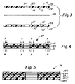
- Each single-sided disk has an information area (13, 13'), a central non-information area (19, 19') and a peripheral non-information (22, 22').
- a durable flexible double-sided adhesive tape (25) placed between the recording sides of the two single-sided disks 10 and 10', so that the surfaces of both single-sided disks face the adhesive tape 25.
- the adhesive tape 25 extends over the entire face of the recording side of the disks 10 and 10''.
- the two single-sided disks 10 and 10' are assembled as a "sandwich" 27 by mechanically pressing them together under vacuum only, non-information areas denoted by the letter "P" in Figure 4,' in order to seal the laminate structure and form a double-sided disk having low birefringence.
- the pressure "P” is applied only at the peripheral non-information areas 23 and 23', and 20 and 20'.
- the vacuum is released, the information surfaces 13 and 13' are pressed against the double sided tape 25 by the atmospheric pressure.
- the type of adhesive which is used for the invention is not critical from the standpoint of its composition.
- the adhesive should be free of corrosive ions such as chloride ions. It is, however, necessary that the adhesive be a compliant (soft) adhesive so that it will deform adequately during lamination.
- thermosetting adhesives, thermoplastic adhesives and contact adhesive films can be used so long as they are deformable under the lamination conditions of temperature and pressure.
- Adhesives which remain soft after application are preferred because they have less tendency to transmit vibrations and less tendency to incur mechanical stresses as well.
- the adhesives are preferred to be substantially non-crystalline in character, i.e. amorphous, but may nevertheless contain a minor amount of crystallinity.
- Adhesive application temperatures are generally in the range of -30 to 80C, this being mainly a function of the thermorheological properties of the adhesive.
- the thickness of the adhesive layer will usually be on the order of 25-75 microns.
- Pressure sensitive two-sided tape, hot melt, or other types of adhesives such as epoxy or urethane based, for example, may be used in the practice of this invention.
- hot melt adhesives examples include, Eurelon® 2138, a thermoplastic polyamide resin, which is a condensate of dimerized fatty acids reacted with diamines, from Shearex Company, Dublin, OH.
- Jet Melt® Adhesive 3748-TC a hydrocarbon resin mixed with rubber, polypropylene, polyethylene, and aliphatic wax, from 3M COMPANY, Minneapolis, MN.
- Evergrip® PS450-56 hot melt adhesive based on a block copolymer styrene-butylene-ethylene-styrene, from A.C.I. Japan, Tokyo, Japan.
- the tape comprises a central substrate 25A, preferably made from Mylar® polyester, on which there are laminated two adhesive layers 25B, and 25B', one on each side of 25A.
- a suitable adhesive layer to be used for this application is an adhesive coating on a release layer, sold by 3M Company under the name "467 Hiperformance Adhesive".
- the thickness of the Mylar substrate is preferably 75 to 175 micrometers, while the thickness of each adhesive layer 25B and 25B' is preferably 25 to 75 micrometers.
- the "467 Hiperformance Adhesive" layer is approximately 50 micrometers thick.
- release layers 25C and 25C' are present before the composite tape is employed for the construction of the double sided disk.
- the adhesive should be made out of low-outgasing, thoroughly stable, high performance material, such as acrylic and silicone adhesives. It is very important for the long range quality of the disk to use adhesives which are insensitive to the everyday environment, i.e. heat, humidity and air quality.
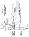
- press 40 shown in Figure 6, may be used to make a double-sided disk characterized by low birefringence.
- Press 40 comprises a bell jar 44, which forms vacuum chamber 46 when sealed on top of bottom platen 70 with O-ring seal 64.
- Top platen 80 disposed above bottom platen 80 is connected to press shaft 48 through flex coupling 54.
- the bell jar 44 is provided with a backfill vent 50, which is closed while chamber 46 is under evacuation, and which is opened to allow air pass through it after the pressing operation has been completed.
- the evacuation of chamber 46 is performed through port 51.
- Both top and bottom platens have cavity vents 58, 58' and 60, 60', respectively, to allow chamber 46 communicate with cavities 66 and 66'.
- Cavities 66 and 66' are designed to be commensurate to the size of the information surfaces 13 and 13' so that no mechanical pressure is applied on these surfaces at any time.
- the top and bottom platens are shaped and sized such as to be capable of mechanically pressing onto both central and peripheral non-information areas 20, 20', and 23, 23', respectively.
- guiding post 72 is attached to the bottom platen, preferably to the center of the platen, to provide guidance or centering to the components of the double-sided disk.
- the size and position of post 72 should be commensurate to the size of position of opening 21, which preferably is located at the center of each component of the disk.
- Elastic O-ring 73 slightly protruding from the surface of the guiding post 72 to support components of the magneto-optical disk during the process of each formation.
- bell jar 44 as well as top platen 80 are initially at a raised position.
- a single sided disk is passed through guiding post 72 and is positioned on top of platen 70, with the information surface facing up.
- One of the two liners for example liner 25C', shown in Figure 5, is peeled off the composite structure 26 such as to allow adhesive 25B' to be uncovered.
- the remaining structure 26 with the uncovered adhesive layer 25B' is positioned on top of single sided disk 20' through guide 72 and through O-ring 73.
- Bell 44 is then lowered all the way so as to be sealed through ring 64 over the lower bottom platen 70, backfill vent 50 is closed, and a vacuum is drawn through port 51.
- the top platen 80 When the vacuum has been formed, the top platen 80 is lowered and presses the structure over the bottom platen 70 at the central 19' and peripheral 22' high pressure contact zones. After the pressure has been applied, the vacuum is removed through backfill vent 50, and the bell 44 is raised.
- the second release liner 25C is then removed leaving the adhesive layer 25B in an exposed condition.
- a second single sided disk 20 is positioned through guide 72 on top of O-ring 73, with its information surface 13 facing the exposed adhesive.
- O-ring 73 protrudes adequately from the surface of guide 72 to hold a disk in a raised position, but it allows the disk to pass through, if an adequate pressure, exceeding a certain limit is applied on the disk.
- Bell 44 is again lowered all the way so as to be sealed through ring 64 over the lower bottom platen 70, backfill vent 50 is closed, and a vacuum is drawn through port 51.
- the pressure within bell 44 should be less than 200 mm Hg, and preferably around 50 mm Hg.
- Pressures lower than 0.03 kilograms per square centimeter are not very effective, while if they exceed 0.7 kilograms per square centimeter they may start introducing again stresses even over the information portions, which in turn are translated to unacceptable birefringence noise.
- the pressure should be applied for more than 3 seconds, more preferably more than 5 seconds, and most preferably for 13 to 17 seconds. By applying the pressure for a longer time than 13 to 17 seconds, no improvements in performance are obtained.
- Application of the mechanical pressure for less than 3 seconds has in most cases the same effect as the application of lower pressure would have had.
- top platen 80 is also raised and the double sided magneto-optical disk thus formed is removed and placed in a proper casing.
- the surfaces of coatings in general, and for that matter the surfaces of the adhesive structures used according to the present invention have a slight orange peel configuration and appearance, which shows up even after the two single-sided disks have bonded to a double sided disk by the process described above.
- the contact between the disk and the adhesive is not absolutely continuous, but it follows the ridges of the orange peel configuration.
- the contact area In the high pressure contact zones, where mechanical pressure has been applied, lower parts of the adhesive's ridges are also brought in contact with the disk, thus increasing the total contact area. Upon release of the pressure, the contact area still remains higher as compared to portions where no mechanical pressure has ever been applied, thus providing better adhesion and bonding between the adhesive and the disk.
- the high pressure contact zones become visible, and remain visible even after removal of the pressure. These zones, due to the fact that they were subjected to higher pressures during the process, have resulted in high contact zones, looking more shiny when observed in an angle, having reduced orange peel and exhibiting higher contact.
- the two parts of the operation may be carried out in one apparatus or in two different apparatuses.
- Yields from other batches of disks made according to the present invention had values of 53.6, 41.0, 57.0, and 90.0, while the standard method yields continued to be very low or even zero.
- a second single sided disk is positioned through guide 72 on top of O-ring 73, with its information surface and the coated side facing the down O-ring 73 protrudes adequately from the surface of guide 72 to hold a disk in a raised position, but it allows the disk to pass through, if an adequate pressure, exceeding a certain limit is applied on the disk.
- Bell 44 is lowered all the way so as to be sealed through ring 64 over the lower bottom platen 70, backfill vent 50 is closed, and a vacuum is drawn through port 51.
- the pressure within bell 44 should be less than 200 mm Hg, and preferably around 50 mm Hg, as already discussed.
- the top platen 80 is lowered forcing initially the single sided disk held by the O-ring to fall into place over the single sided disk supported by the bottom platen 70, and then it presses the two disks together over platen 70 at the central 19 and 19', and peripheral 22 and 22' high pressure contact zones, with a pressure of 0.03 to 0.7 kilograms per square centimeter, preferably 0.03 to 0.3 kilograms per square centimeter, and even more preferably 0.07 to 0.2 kilograms per square centimeter.
- the time of applying this pressure should be more than 3 seconds, more preferably more than 5 seconds, and most preferably 13 to 17 seconds. By applying the pressure for a longer time, no improvements in performance are obtained.
- top platen 80 is also raised and the double sided magneto-optical disk thus formed is removed and placed in a proper casing.
- the mean birefringence value in the case of the disks made according to the present invention was 0.44 mV with a standard deviation of 0.07, while in the case of disks made with the standard method, the mean value was 0.57 mV with a standard deviation of 0.14
Landscapes
- Engineering & Computer Science (AREA)
- Mechanical Engineering (AREA)
- Physics & Mathematics (AREA)
- Fluid Mechanics (AREA)
- Manufacturing Optical Record Carriers (AREA)
Applications Claiming Priority (2)
| Application Number | Priority Date | Filing Date | Title |
|---|---|---|---|
| US07/530,350 US5146438A (en) | 1990-05-30 | 1990-05-30 | Method of making double-sided magneto-optical disks having reduced birefringence |
| US530350 | 1990-05-30 |
Publications (2)
| Publication Number | Publication Date |
|---|---|
| EP0463382A2 true EP0463382A2 (de) | 1992-01-02 |
| EP0463382A3 EP0463382A3 (en) | 1992-02-26 |
Family
ID=24113335
Family Applications (1)
| Application Number | Title | Priority Date | Filing Date |
|---|---|---|---|
| EP19910108525 Withdrawn EP0463382A3 (en) | 1990-05-30 | 1991-05-25 | Method of making double-sided magneto-optical disks having reduced birefringence |
Country Status (3)
| Country | Link |
|---|---|
| US (1) | US5146438A (de) |
| EP (1) | EP0463382A3 (de) |
| JP (1) | JPH0668531A (de) |
Cited By (6)
| Publication number | Priority date | Publication date | Assignee | Title |
|---|---|---|---|---|
| WO1998057799A1 (en) * | 1997-06-17 | 1998-12-23 | Elf Atochem S.A. | Preparation of a recording carrier |
| USRE36806E (en) * | 1994-07-29 | 2000-08-01 | 3M Innovative Properties Company | Internally damped rotatable storage article |
| WO2000077782A1 (de) * | 1999-06-16 | 2000-12-21 | Steag Hamatech Ag | Vorrichtung und verfahren zum beschichten eines optisch lesbaren datenträgers |
| WO2000077781A1 (de) * | 1999-06-16 | 2000-12-21 | Steag Hamatech Ag | Vorrichtung und verfahren zum beschichten eines optisch lesbaren datenträgers |
| WO2000077784A1 (de) * | 1999-06-16 | 2000-12-21 | Steag Hamatech Ag | Vorrichtung und verfahren zum herstellen eines datenträgers |
| US6428872B1 (en) | 1998-06-15 | 2002-08-06 | Atofina | Preparation of a recording carrier |
Families Citing this family (17)
| Publication number | Priority date | Publication date | Assignee | Title |
|---|---|---|---|---|
| JPH06131705A (ja) * | 1992-10-16 | 1994-05-13 | Hitachi Ltd | 光ディスク貼り合わせ装置 |
| US5726969A (en) * | 1994-12-28 | 1998-03-10 | Matsushita Electric Industrial Co., Ltd. | Optical recording medium having dual information surfaces |
| BR9605938A (pt) * | 1995-03-16 | 1997-08-12 | Toshiba Kk | Estrutura de disco ótico método de fabricação da mesma e aparelho para fabricação da mesma |
| US5759332A (en) * | 1995-05-22 | 1998-06-02 | Pioneer Electronic Corporation | Process of reproducing optical discs and optical discs produced by the same |
| US5951806A (en) * | 1995-11-30 | 1999-09-14 | Kitano Engineering Co., Ltd. | Method of manufacturing a storage disc |
| US5757978A (en) * | 1996-07-18 | 1998-05-26 | Medar, Inc. | Method and system for detecting localized birefringence defects in a dynamic global birefringence field |
| US6527904B1 (en) * | 1996-11-14 | 2003-03-04 | Pioneer Electronic Corporation | Method of producing an optical video disc |
| JP3014979B2 (ja) * | 1997-01-21 | 2000-02-28 | 日東電工株式会社 | 光ディスク製造方法およびそれに用いる装置 |
| JPH10208319A (ja) * | 1997-01-28 | 1998-08-07 | Kitano Eng Kk | ディスク基板の貼り合わせ方法 |
| GB2326014A (en) * | 1997-05-16 | 1998-12-09 | Jan Robert Coyle | A two-sided digital disc |
| DE69933072T2 (de) | 1998-01-27 | 2006-12-21 | Kitano Co., Ltd., Komatsushima | Verfahren und Vorrichtung zum Laminieren plattenförmiger Substrate |
| JPH11283279A (ja) | 1998-01-30 | 1999-10-15 | Minnesota Mining & Mfg Co <3M> | 貼り合わせ型光ディスク並びにその製造方法及び装置 |
| US6599602B2 (en) | 1999-06-02 | 2003-07-29 | 3M Innovative Properties Company | Polycarbonate articles and adhesive composition therefor |
| WO2001030872A1 (en) | 1999-10-28 | 2001-05-03 | 3M Innovative Properties Company | Compositions and articles made therefrom |
| DE10008111A1 (de) * | 2000-02-22 | 2001-08-23 | Krauss Maffei Kunststofftech | Vorrichtung zum Vakuumpressen von DVD-Substraten |
| JP2002175646A (ja) * | 2000-09-28 | 2002-06-21 | Pioneer Electronic Corp | ディスク作製方法及びディスク転写方法 |
| US8376013B2 (en) * | 2008-03-11 | 2013-02-19 | Duke University | Plasmonic assisted systems and methods for interior energy-activation from an exterior source |
Family Cites Families (11)
| Publication number | Priority date | Publication date | Assignee | Title |
|---|---|---|---|---|
| JPS5766540A (en) * | 1980-10-09 | 1982-04-22 | Toshiba Corp | Optical information storage carrier and its manufacture |
| US4449138A (en) * | 1981-04-15 | 1984-05-15 | Tokyo Shibaura Denki Kabushiki Kaisha | Information recording medium |
| US4740947A (en) * | 1984-04-25 | 1988-04-26 | Sharp Kabushiki Kaisha | Dual surface optical memory disc |
| US4911968A (en) * | 1985-02-18 | 1990-03-27 | Hitachi Maxell, Ltd. | Optical disc |
| JP2585520B2 (ja) * | 1985-12-27 | 1997-02-26 | 株式会社日立製作所 | 相変化記録媒体 |
| JPS62185264A (ja) * | 1986-02-12 | 1987-08-13 | Fuji Photo Film Co Ltd | 情報記録媒体 |
| US4892606A (en) * | 1986-08-28 | 1990-01-09 | Canon Kabushiki Kaisha | Optical recording medium having space therein and method of manufacturing the same |
| JPS6432440A (en) * | 1987-07-27 | 1989-02-02 | Mitsui Petrochemical Ind | Production of substrate for information recording |
| JPS6443830A (en) * | 1987-08-11 | 1989-02-16 | Mitsui Petrochemical Ind | Production of substrate for information recording |
| JPH01154331A (ja) * | 1987-12-09 | 1989-06-16 | Pioneer Electron Corp | 光学式情報記録円盤 |
| JP2656785B2 (ja) * | 1988-02-24 | 1997-09-24 | 日東電工株式会社 | 光デイスク |
-
1990
- 1990-05-30 US US07/530,350 patent/US5146438A/en not_active Expired - Fee Related
-
1991
- 1991-05-25 EP EP19910108525 patent/EP0463382A3/en not_active Withdrawn
- 1991-05-29 JP JP3124275A patent/JPH0668531A/ja active Pending
Cited By (7)
| Publication number | Priority date | Publication date | Assignee | Title |
|---|---|---|---|---|
| USRE36806E (en) * | 1994-07-29 | 2000-08-01 | 3M Innovative Properties Company | Internally damped rotatable storage article |
| WO1998057799A1 (en) * | 1997-06-17 | 1998-12-23 | Elf Atochem S.A. | Preparation of a recording carrier |
| US6261660B1 (en) | 1997-06-17 | 2001-07-17 | Atofina | Preparation of a recording carrier |
| US6428872B1 (en) | 1998-06-15 | 2002-08-06 | Atofina | Preparation of a recording carrier |
| WO2000077782A1 (de) * | 1999-06-16 | 2000-12-21 | Steag Hamatech Ag | Vorrichtung und verfahren zum beschichten eines optisch lesbaren datenträgers |
| WO2000077781A1 (de) * | 1999-06-16 | 2000-12-21 | Steag Hamatech Ag | Vorrichtung und verfahren zum beschichten eines optisch lesbaren datenträgers |
| WO2000077784A1 (de) * | 1999-06-16 | 2000-12-21 | Steag Hamatech Ag | Vorrichtung und verfahren zum herstellen eines datenträgers |
Also Published As
| Publication number | Publication date |
|---|---|
| EP0463382A3 (en) | 1992-02-26 |
| JPH0668531A (ja) | 1994-03-11 |
| US5146438A (en) | 1992-09-08 |
Similar Documents
| Publication | Publication Date | Title |
|---|---|---|
| US5146438A (en) | Method of making double-sided magneto-optical disks having reduced birefringence | |
| JP4160697B2 (ja) | 情報記録ディスクおよびその製造方法 | |
| CA2310706A1 (en) | Optical recording medium and disc cartridge | |
| US20020085482A1 (en) | Optical recording medium and method of manufacturing the same | |
| JPH0750035A (ja) | 光ディスクの製造方法及びその製造装置 | |
| JPH01287841A (ja) | 光情報記録媒体 | |
| JPH06274940A (ja) | 光ディスク及びその製造方法 | |
| US5635268A (en) | Optical recording medium | |
| JPS6168744A (ja) | 光学的記録媒体の製造方法 | |
| JPS63113831A (ja) | 光カ−ド | |
| JPH09274735A (ja) | 光ディスク | |
| US5305254A (en) | Magneto-optic memory device | |
| JPH0356889Y2 (de) | ||
| JPH02183443A (ja) | 光記録媒体 | |
| JPH0490146A (ja) | 光情報記録媒体 | |
| JPS6355745A (ja) | 両面型光記録媒体 | |
| EP0321250B1 (de) | Magneto-optisches Speichergerät | |
| JPH04344344A (ja) | 密着貼り合わせ型光情報記録媒体 | |
| JPS6356833A (ja) | 光磁気デイスク | |
| JPH0553023B2 (de) | ||
| JPH07262619A (ja) | 光学的情報記録媒体 | |
| JPH07121852A (ja) | 磁気記録媒体及び磁気記録シート及びディスク状記録媒体 | |
| JPH08329526A (ja) | 光ディスク | |
| JPH0312842A (ja) | 光メモリ素子 | |
| JPH0442446A (ja) | 情報記録媒体およびその製造方法 |
Legal Events
| Date | Code | Title | Description |
|---|---|---|---|
| PUAI | Public reference made under article 153(3) epc to a published international application that has entered the european phase |
Free format text: ORIGINAL CODE: 0009012 |
|
| AK | Designated contracting states |
Kind code of ref document: A2 Designated state(s): DE FR GB IT NL |
|
| PUAL | Search report despatched |
Free format text: ORIGINAL CODE: 0009013 |
|
| AK | Designated contracting states |
Kind code of ref document: A3 Designated state(s): DE FR GB IT NL |
|
| 17P | Request for examination filed |
Effective date: 19920701 |
|
| RAP1 | Party data changed (applicant data changed or rights of an application transferred) |
Owner name: N.V. PHILIPS' GLOEILAMPENFABRIEKEN |
|
| 17Q | First examination report despatched |
Effective date: 19941004 |
|
| STAA | Information on the status of an ep patent application or granted ep patent |
Free format text: STATUS: THE APPLICATION IS DEEMED TO BE WITHDRAWN |
|
| 18D | Application deemed to be withdrawn |
Effective date: 19950215 |