EP0463725A2 - Dispositif d'affichage avec un interrupteur du type "Reed" - Google Patents
Dispositif d'affichage avec un interrupteur du type "Reed" Download PDFInfo
- Publication number
- EP0463725A2 EP0463725A2 EP91304087A EP91304087A EP0463725A2 EP 0463725 A2 EP0463725 A2 EP 0463725A2 EP 91304087 A EP91304087 A EP 91304087A EP 91304087 A EP91304087 A EP 91304087A EP 0463725 A2 EP0463725 A2 EP 0463725A2
- Authority
- EP
- European Patent Office
- Prior art keywords
- core
- reed switch
- display device
- movable element
- disk
- Prior art date
- Legal status (The legal status is an assumption and is not a legal conclusion. Google has not performed a legal analysis and makes no representation as to the accuracy of the status listed.)
- Granted
Links
- 235000014676 Phragmites communis Nutrition 0.000 title claims abstract description 59
- 230000004907 flux Effects 0.000 claims abstract description 18
- 238000004804 winding Methods 0.000 claims description 3
- 239000000835 fiber Substances 0.000 description 8
- 230000003190 augmentative effect Effects 0.000 description 4
- 239000000463 material Substances 0.000 description 4
- 230000000873 masking effect Effects 0.000 description 3
- 230000000694 effects Effects 0.000 description 1
- 239000003365 glass fiber Substances 0.000 description 1
- 238000005286 illumination Methods 0.000 description 1
- 230000009916 joint effect Effects 0.000 description 1
- 239000000696 magnetic material Substances 0.000 description 1
- 230000005415 magnetization Effects 0.000 description 1
- 230000010287 polarization Effects 0.000 description 1
- 230000005855 radiation Effects 0.000 description 1
Images




Classifications
-
- G—PHYSICS
- G09—EDUCATION; CRYPTOGRAPHY; DISPLAY; ADVERTISING; SEALS
- G09F—DISPLAYING; ADVERTISING; SIGNS; LABELS OR NAME-PLATES; SEALS
- G09F9/00—Indicating arrangements for variable information in which the information is built-up on a support by selection or combination of individual elements
- G09F9/30—Indicating arrangements for variable information in which the information is built-up on a support by selection or combination of individual elements in which the desired character or characters are formed by combining individual elements
- G09F9/37—Indicating arrangements for variable information in which the information is built-up on a support by selection or combination of individual elements in which the desired character or characters are formed by combining individual elements being movable elements
- G09F9/375—Indicating arrangements for variable information in which the information is built-up on a support by selection or combination of individual elements in which the desired character or characters are formed by combining individual elements being movable elements the position of the elements being controlled by the application of a magnetic field
Definitions
- This invention relates to a display element designed to provide a bright or dark appearance either as a single element or as a pixel in an array, using a reed switch, and also relates to a reed switch control arrangement.
- the display elements with which the invention is concerned have a movable element movable relative to a stationary element between ON and OFF positions and in these positions to provide a bright area or a dark area, respectively, visible in the viewing direction.
- a permanent magnet is provided movable with the movable element.
- a switchable magnetic core is provided on the stationary element located and adapted in one and the other polarity to cooperate with the permanent magnet to move the movable element to ON and OFF position, respectively.
- the core is of a high remanence material surrounded by an energizing winding which may be pulsed by an energizing current to switch the core polarity in an interval much less than the interval for the movable element to move between ON and OFF position.
- this invention is particularly concerned with display elements as above defined where the display of the bright area in the viewing direction in the ON position is augmented by a luminous source such as a light emitting diode ('LED') or an optic fibre and where such source must be turned off or masked from the viewer in the OFF position.
- a luminous source such as a light emitting diode ('LED') or an optic fibre
- 'LED' light emitting diode
- optic fibre An example of such display element using an optic fibre is
- Such light-augmented element is particularly useful with 'writable' highway signs which are adapted to be read from some distance.
- Such signs will be formed of an array of display elements acting as pixels individually selectively switchable to display light or dark areas collectively providing information to the motorist.
- the luminous source be focussed to a beam about the viewing direction narrower than the viewing cone of the element as a whole to attract the driver's attention so that he, then, looks at the display as a whole, obtaining the information it displays from the collective effect of both its bright areas and dark areas with the bright areas augmented by the luminous sources in each pixel.
- the display element which is light-augmented in its ON position, defines a viewing cone centred about a viewing direction which viewing cone may have an apex angle larger than 90° and where within the cone there is a smaller focussed light beam cone when the element is ON with an apex angle of about 15° within the viewing cone.
- the first and second cores are approximately parallel and located and adapted so that when both cores have similar polarity the collective return flux of the two cores causes the switch to assume one state and when the two cores have opposite polarities causes the switch to assume the other state.
- the switch is connected so that one state turns on or exposes the light source and the other state turns off or masks the light source.
- the masking of the light source requires either 180° rotation of the disk or the presence of a special masking addition to the disk.
- the 180° rotation reduces the strength of the magnetic drive while the masking addition adds to the cost of the disk.
- the reed switch controlled by the switchable core provides a easy control for switching ON and OFF a light source such as an incandescent lamp or light emitting diode ('LED').
- a light source such as an incandescent lamp or light emitting diode ('LED').
- the reed switch may be connected to operate a shutter in the optic path, which includes the fibre, or, if the fibre has an individual light source may switch ON and OFF that source like the lamp or LED in the previous example.
- the reed switch controlled by the switchable core may be used for other purposes than control of the light source or light path.
- the reed-switched line may be used to signal the magnetic core state back to a scanner or control.
- the controlled reed switch could be used for other purposes, such as driving a slave display, of the same or different type.
- the display element shown in Figures 1-4 may be either a single status element or part of an array of the type shown in Figure 6.
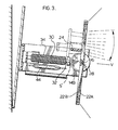
- Figure 1 shows a base plate 12 supporting opposed standards 14A, 14B slotted at the outer end of the standard to mount the shaft 16 of a display disk 18.
- the display disk 18 has a circular frame 20 which mounts a circle of resilient plastic material 22 as shown.
- the resilient plastic material 22 is brightly colored on one side 22A to be displayed in the viewing direction in the ON position ( Figure 3) where it contrasts with the background.
- the resilient plastic material 22 is dark on the other side 22B to match the background, (and the rim of the disk) so that the area to the viewer is bright in the ON position and is dark in the OFF position. (The resilient plastic 22 is omitted in Figure 2).
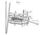
- the display disk is pivotted to rotate on shaft 16 between stop 24 mounted on standard 14B, which stops the rotation of the disk at the ON position Figure 3 (displaying the bright face of the disk in the viewing direction V) and the pillar 26 to be described hereafter used stops the disk in the OFF position ( Figure 4). It will be noted that in the OFF position the viewer sees the dark edge of the disk and the dark background of the element where the bright disk side was in ON position.
- Rotatable with the disk 18 on shaft 16 is a cylindrical permanent magnet 28 magnetized along a diameter as shown in Figures 3 and 4.
- Core 30 of preferably high remanence magnetic material preferably of extended straight form is mounted on standard 14B to project therefrom in the viewing direction and to provide its outer pole 32 in the vicinity of the locus of permanent magnet 28.
- the core pole 32 is positioned relative to the magnetic axis of the permanent magnet 28 and the stops 24 and 26 to cause the disk to alternate between ON and OFF positions on each switch of polarity of pole 32.
- Energizing coil 34 surrounds core to provide from a source not shown, the energizing current to switch the core polarity.
- the core 30 is of the 'hard' or high remanence type so that the switching of the core may be performed by a very short pulse of energizing current in an interval much shorter than required for the element to mechanically move between ON and OFF position.
- the magnetic torque to complete the mechanical movement and to hold the element in place afterward is provided by the remanent flux of the magnetic core, 30.
- the switched polarities of pole 32 are indicated as N′, S′.
- the element switched as described may be used alone or as part of the array of Figure 6 as so far described operates in accord with design and operating principles well known before this development.
- the bright side of the disk is augmented in the disk's ON position by the presence of a light source 'on' or illuminated in the ON position and 'off' in the OFF position under the control of a reed switch to be described.
- the disk is provided with a round aperture 40 displaced from the disk axis and a bank of seven LED's 42 is provided to shine through the aperture 40 in the ON position of the disk.
- the LED bank is supported on the outer end of pillar 26.
- the LEDs are preferably provided with focussing lenses so that their rays shine principally in a cone of 15° apex centred on viewing direction V.
- Figure 2 there is indicated in dotted form a cylindrical side wall or shroud which is preferably provided above the LED bank to limit side radiation or reflection. The side wall is not shown in the remaining Figures to allow better display of the remaining elements.
- a reed switch 44 well known to those skilled in the art is supported on the base parallel and adjacent to the switchable core 30.
- the reed switch is designed to be closed when there is a sufficient flux field with a component along the longitudinal axis of the reed switch and open when such field is insufficient.
- This reed switch is normally open.
- a normally closed reed switch could be used although, in the preferred operating arrangement it might render the circuit more complex.
- a second longitudinally extending core 46 is located parallel to the longitudinal axis reed switch 44 about equally spaced from the reed switch as core 30 and on the opposite side therefrom.
- the second core has preferably approximately the same remanance as core 30.
- the second core is not switched but has a permanent polarization as shown.
- the reed switch 44 is connected in series with the bank of LEDs as schematically shown in Figure 7 but the LEDs could be connected in parallel with each other as determined by the supply voltage. With the circuit of Figure 7, a resistor 43 is provided in series with the LED's to limit current to the LED's. When the reed switch is closed and open, the LED's are on and off respectively. The mode of operation of the reed switch is as demonstrated in Figures 8 and 9.
- switchable core 30 has been switched to make pole 32, south (S′) drive the display element to ON position as shown in Figure 3.
- the polarity of the second core 46 is chosen so that with the switchable core 30 in ON magnetization both cores have the same polarity as shown in Figure 9.
- some of the return flux of the two cores is combined along the length of the reed switch and the location and remanence of the cores is chosen so that the combined flux along such length closes the reed switch illuminating the LED bank which augments the bright side of the disk to a viewer in the viewing direction.
- the first core 30 When it is desired that the disk be in OFF orientation the first core 30 is switched to make pole 32 north N′ (Figure 8). Since the first and second cores are now of opposite polarity each core acts as a preferred path for a high proportion of the other's return flux.
- the magnetic parameters and the reed switch are selected so that the flux along the reed switch is insufficient to close it so that it opens, extinguishing the LED bank.
- the viewer on the highway sees a dark area of the disk (where the bright area would be in 'ON' state), being the dark background, the edge of the disk and the 'off' LED's, a dark pixel in the array shown schematically in Figure 6.
- the LED's will customarily be provided with lenses, focussing the bright in a beam preferably 15° on the highway at a described distance from the sign.
- the viewing angle for the bright disk sides and the counterpart dark pixels will be much wider usually >90°.
- the light source may alternatively be incandescent or optic fibres.
- the incandescent light may be switched on and off by the reed switch just as are the LED's.
- the light supply of the optic fibre for each pixel may also be switched on and off if there is a separate light for each pixel fibre. If there is one light for all fibres in the array the reed switch would be connected to operate a shutter to interrupt the corresponding optic fibre path.
- the first and second cores are shown oppositely disposed relative to the reed switch. Magnetic parameters can be selected so that these cores may be nearer to each other say at the corners (with the reed switch) of a equilateral triangle. Obviously the second core must be located far enough from the locus of the permanent magnet so that the second core does not affect the magnet's drive.
- the first and second cores may be different distances from the reed switch (and of different remanence) as long as their locations are selected so that the flux places the reed switch in a state determined by the polarity of the first core.
- the first and second cores need not be precisely parallel but compactness and ease of calculation of parameters will usually be improved if the two cores are approximately parallel.
- the reed switch need not be precisely parallel to the two cores but the usual mode of operation of the reed switch requires that the cores provide return flux paths with a substantial component in the direction of the longitudinal axis of the reed switch.
- the reed switch may if desired be of the type which opens for flux values above a pre-determined value and closes below such value. However, this will complicate the switching control for the light source in the arrangement of the preferred embodiment.
- the reed switch may be used for other functions than the switching of the illumination.
- the reed switch, controlled as above described may be used to signal the magnetic status of the first core to a control or supervisory device.
- Figure 10 shows that more than one reed switch may be controlled by the same switchable core 30.
- a normally open reed switch 44 is located on each side of the switchable core.
- Two permanent polarity cores 46 are located each on the opposite side of a reed switch from the switchable core. The two permanent polarity cores are polarized in opposite directions as shown. At any time the combination of the return flux of the switchable core with the respective second and third cores will produce closed and an open state reed switches. These states will be reversed when the switchable core 30 is switched to the opposite polarity.
Landscapes
- Physics & Mathematics (AREA)
- General Physics & Mathematics (AREA)
- Engineering & Computer Science (AREA)
- Theoretical Computer Science (AREA)
- Devices For Indicating Variable Information By Combining Individual Elements (AREA)
- Illuminated Signs And Luminous Advertising (AREA)
- Road Signs Or Road Markings (AREA)
- Circuit Arrangement For Electric Light Sources In General (AREA)
- Switches That Are Operated By Magnetic Or Electric Fields (AREA)
Applications Claiming Priority (2)
| Application Number | Priority Date | Filing Date | Title |
|---|---|---|---|
| US07/522,739 US5050325A (en) | 1990-05-14 | 1990-05-14 | Display indicator and reed switch |
| US522739 | 1990-05-14 |
Publications (3)
| Publication Number | Publication Date |
|---|---|
| EP0463725A2 true EP0463725A2 (fr) | 1992-01-02 |
| EP0463725A3 EP0463725A3 (en) | 1992-07-29 |
| EP0463725B1 EP0463725B1 (fr) | 1996-01-17 |
Family
ID=24082131
Family Applications (1)
| Application Number | Title | Priority Date | Filing Date |
|---|---|---|---|
| EP91304087A Expired - Lifetime EP0463725B1 (fr) | 1990-05-14 | 1991-05-07 | Dispositif d'affichage avec un interrupteur du type "Reed" |
Country Status (5)
| Country | Link |
|---|---|
| US (1) | US5050325A (fr) |
| EP (1) | EP0463725B1 (fr) |
| JP (1) | JP3205569B2 (fr) |
| CA (1) | CA2041375C (fr) |
| DE (1) | DE69116447T2 (fr) |
Cited By (7)
| Publication number | Priority date | Publication date | Assignee | Title |
|---|---|---|---|---|
| EP0561586A1 (fr) * | 1992-03-20 | 1993-09-22 | Mark IV Industries Limited | Obturateur électromagnétique |
| EP0731435A1 (fr) * | 1995-03-08 | 1996-09-11 | Lite Vision Corporation | Dispositif d'affichage à commande magnétique |
| FR2731828A1 (fr) * | 1995-03-17 | 1996-09-20 | Jc Decaux | Cellule elementaire d'affichage a pastille pivotante pour panneau d'affichage a matrices de points |
| WO1999017267A1 (fr) | 1997-09-30 | 1999-04-08 | Transit-Media Gmbh Systemtechnik Für Fahrgastinformation | Procede de montage d'elements indicateurs a segments basculants derriere des vitres |
| FR2824173A1 (fr) * | 2001-03-09 | 2002-10-31 | Centaure Stystems | Dispositif d'affichage a pixels mecaniques eclaires |
| US6603458B1 (en) * | 1998-01-22 | 2003-08-05 | Annex Anzeignsysteme Gmbh | Electromagnetic display device |
| AT414165B (de) * | 2001-10-09 | 2006-09-15 | Gifas Electric Ges M B H | Leuchte |
Families Citing this family (10)
| Publication number | Priority date | Publication date | Assignee | Title |
|---|---|---|---|---|
| US5325108A (en) * | 1990-03-02 | 1994-06-28 | Unisplay S.A. | Information displays |
| US5793343A (en) * | 1994-10-27 | 1998-08-11 | American Signal Company | Display apparatus for signage |
| US5642130A (en) * | 1995-01-17 | 1997-06-24 | Mark Iv Industries Limited | Display array and power control circuit |
| US5898418A (en) * | 1995-03-06 | 1999-04-27 | Kao; Pin-Chi | Magnetically operated display |
| US5771616C1 (en) * | 1996-07-19 | 2001-07-03 | Mark Iv Ind Ltd | Display device with disk and led |
| WO1997033266A1 (fr) * | 1996-03-05 | 1997-09-12 | Mark Iv Industries Limited | Dispositif et ensemble d'affichage |
| CA2171054C (fr) * | 1996-03-05 | 1999-05-25 | Veso S. Tijanic | Dispositif d'affichage disque lumineux |
| US6278431B1 (en) * | 1996-11-18 | 2001-08-21 | Lite Vision Corporation | Magnetically operated display |
| FR2761189B1 (fr) * | 1997-03-21 | 1999-06-04 | J C Decaux International | Panneau d'affichage de messages a matrices de points |
| DE19802218B4 (de) * | 1998-01-22 | 2010-11-25 | Annax Anzeigesysteme Gmbh | Elektromagnetische Anzeigevorrichtung |
Family Cites Families (6)
| Publication number | Priority date | Publication date | Assignee | Title |
|---|---|---|---|---|
| US3991496A (en) * | 1975-07-31 | 1976-11-16 | Ferranti-Packard Limited | Gravity bias for display elements |
| IT1076017B (it) * | 1977-02-01 | 1985-04-22 | Nuovo Pignone Spa | Perfezionamenti in un indicatore numerico elettromeccanico a sette segmenti |
| FR2585164B1 (fr) * | 1985-07-22 | 1988-04-22 | Soc Et Dev Prod Electron | Cellule elementaire d'affichage pour panneau d'affichage a matrice de points |
| DE3633957C1 (de) * | 1986-10-06 | 1988-02-18 | Herbert Graf | Vorrichtung zur Verkehrsregelung von Strassenfahrzeugen |
| US4914427A (en) * | 1988-11-03 | 1990-04-03 | The Staver Company Inc. | Matrix display system and method |
| US4974353A (en) * | 1989-08-28 | 1990-12-04 | The Staver Company | Matrix display assembly having multiple point lighting |
-
1990
- 1990-05-14 US US07/522,739 patent/US5050325A/en not_active Expired - Lifetime
-
1991
- 1991-04-26 CA CA002041375A patent/CA2041375C/fr not_active Expired - Fee Related
- 1991-05-07 EP EP91304087A patent/EP0463725B1/fr not_active Expired - Lifetime
- 1991-05-07 DE DE69116447T patent/DE69116447T2/de not_active Expired - Fee Related
- 1991-05-10 JP JP13571891A patent/JP3205569B2/ja not_active Expired - Fee Related
Cited By (8)
| Publication number | Priority date | Publication date | Assignee | Title |
|---|---|---|---|---|
| EP0561586A1 (fr) * | 1992-03-20 | 1993-09-22 | Mark IV Industries Limited | Obturateur électromagnétique |
| EP0731435A1 (fr) * | 1995-03-08 | 1996-09-11 | Lite Vision Corporation | Dispositif d'affichage à commande magnétique |
| FR2731828A1 (fr) * | 1995-03-17 | 1996-09-20 | Jc Decaux | Cellule elementaire d'affichage a pastille pivotante pour panneau d'affichage a matrices de points |
| WO1996029690A1 (fr) * | 1995-03-17 | 1996-09-26 | J.C. Decaux | Cellule elementaire d'affichage a pastille pivotante pour panneau d'affichage a matrices de points |
| WO1999017267A1 (fr) | 1997-09-30 | 1999-04-08 | Transit-Media Gmbh Systemtechnik Für Fahrgastinformation | Procede de montage d'elements indicateurs a segments basculants derriere des vitres |
| US6603458B1 (en) * | 1998-01-22 | 2003-08-05 | Annex Anzeignsysteme Gmbh | Electromagnetic display device |
| FR2824173A1 (fr) * | 2001-03-09 | 2002-10-31 | Centaure Stystems | Dispositif d'affichage a pixels mecaniques eclaires |
| AT414165B (de) * | 2001-10-09 | 2006-09-15 | Gifas Electric Ges M B H | Leuchte |
Also Published As
| Publication number | Publication date |
|---|---|
| DE69116447T2 (de) | 1996-08-08 |
| US5050325A (en) | 1991-09-24 |
| DE69116447D1 (de) | 1996-02-29 |
| JPH04229893A (ja) | 1992-08-19 |
| EP0463725A3 (en) | 1992-07-29 |
| CA2041375C (fr) | 1999-02-16 |
| CA2041375A1 (fr) | 1991-11-15 |
| JP3205569B2 (ja) | 2001-09-04 |
| EP0463725B1 (fr) | 1996-01-17 |
Similar Documents
| Publication | Publication Date | Title |
|---|---|---|
| US5050325A (en) | Display indicator and reed switch | |
| US4694599A (en) | Electromagnetic flip-type visual indicator | |
| US3469258A (en) | Rotating magnetically actuated display or indicator | |
| CA2013663C (fr) | Element d'affichage a disque encoche | |
| JPS6158835B2 (fr) | ||
| US4295127A (en) | Information display device | |
| US4794391A (en) | Display matrix incorporating light-conducting fibers and light-occulting shutters | |
| US4914427A (en) | Matrix display system and method | |
| JP3199900B2 (ja) | シヤツター | |
| US6278431B1 (en) | Magnetically operated display | |
| US3537197A (en) | Lever operated display device | |
| EP0556954B1 (fr) | Dispositif d'affichage | |
| US6181315B1 (en) | Magnetically operated display | |
| US3581301A (en) | Display arrangement for symbols | |
| EP0885437B1 (fr) | Dispositif et ensemble d'affichage | |
| CA1205932A (fr) | Element electromecanique distinct, et grand panneau publicitaire | |
| US3792540A (en) | Multi-window type display device | |
| US5555339A (en) | Display matrix comprising light-emitting fibers that are maskable by disks each having a plurality of sectors | |
| US4949082A (en) | High speed display device | |
| US3368216A (en) | Rotatable drum indicator with electromagnetic drum control | |
| EP0068726A1 (fr) | Panneau d'affichage | |
| US5721564A (en) | Electromagnetically operated linearly sliding shutter for a variable display | |
| EP1591985A2 (fr) | Dispositif d'affichage électromagnétique | |
| JPH10247064A (ja) | 可変色表示素子とそれを用いた図柄表示装置 | |
| RU2025789C1 (ru) | Индикатор |
Legal Events
| Date | Code | Title | Description |
|---|---|---|---|
| PUAI | Public reference made under article 153(3) epc to a published international application that has entered the european phase |
Free format text: ORIGINAL CODE: 0009012 |
|
| AK | Designated contracting states |
Kind code of ref document: A2 Designated state(s): DE DK ES FR GB IT SE |
|
| PUAL | Search report despatched |
Free format text: ORIGINAL CODE: 0009013 |
|
| AK | Designated contracting states |
Kind code of ref document: A3 Designated state(s): DE DK ES FR GB IT SE |
|
| 17P | Request for examination filed |
Effective date: 19920908 |
|
| 17Q | First examination report despatched |
Effective date: 19940211 |
|
| RAP1 | Party data changed (applicant data changed or rights of an application transferred) |
Owner name: MARK IV INDUSTRIES LIMITED |
|
| GRAA | (expected) grant |
Free format text: ORIGINAL CODE: 0009210 |
|
| AK | Designated contracting states |
Kind code of ref document: B1 Designated state(s): DE DK ES FR GB IT SE |
|
| PG25 | Lapsed in a contracting state [announced via postgrant information from national office to epo] |
Ref country code: DK Effective date: 19960117 |
|
| ITF | It: translation for a ep patent filed | ||
| REF | Corresponds to: |
Ref document number: 69116447 Country of ref document: DE Date of ref document: 19960229 |
|
| PG25 | Lapsed in a contracting state [announced via postgrant information from national office to epo] |
Ref country code: SE Effective date: 19960417 |
|
| PG25 | Lapsed in a contracting state [announced via postgrant information from national office to epo] |
Ref country code: ES Free format text: LAPSE BECAUSE OF FAILURE TO SUBMIT A TRANSLATION OF THE DESCRIPTION OR TO PAY THE FEE WITHIN THE PRESCRIBED TIME-LIMIT Effective date: 19960428 |
|
| ET | Fr: translation filed | ||
| PGFP | Annual fee paid to national office [announced via postgrant information from national office to epo] |
Ref country code: SE Payment date: 19960517 Year of fee payment: 6 |
|
| PLBE | No opposition filed within time limit |
Free format text: ORIGINAL CODE: 0009261 |
|
| STAA | Information on the status of an ep patent application or granted ep patent |
Free format text: STATUS: NO OPPOSITION FILED WITHIN TIME LIMIT |
|
| 26N | No opposition filed | ||
| PGFP | Annual fee paid to national office [announced via postgrant information from national office to epo] |
Ref country code: ES Payment date: 19970523 Year of fee payment: 7 |
|
| REG | Reference to a national code |
Ref country code: GB Ref legal event code: IF02 |
|
| PGFP | Annual fee paid to national office [announced via postgrant information from national office to epo] |
Ref country code: GB Payment date: 20030604 Year of fee payment: 13 |
|
| PGFP | Annual fee paid to national office [announced via postgrant information from national office to epo] |
Ref country code: DE Payment date: 20030605 Year of fee payment: 13 |
|
| PGFP | Annual fee paid to national office [announced via postgrant information from national office to epo] |
Ref country code: FR Payment date: 20030610 Year of fee payment: 13 |
|
| PG25 | Lapsed in a contracting state [announced via postgrant information from national office to epo] |
Ref country code: GB Free format text: LAPSE BECAUSE OF NON-PAYMENT OF DUE FEES Effective date: 20040507 |
|
| PG25 | Lapsed in a contracting state [announced via postgrant information from national office to epo] |
Ref country code: DE Free format text: LAPSE BECAUSE OF NON-PAYMENT OF DUE FEES Effective date: 20041201 |
|
| GBPC | Gb: european patent ceased through non-payment of renewal fee |
Effective date: 20040507 |
|
| PG25 | Lapsed in a contracting state [announced via postgrant information from national office to epo] |
Ref country code: FR Free format text: LAPSE BECAUSE OF NON-PAYMENT OF DUE FEES Effective date: 20050131 |
|
| REG | Reference to a national code |
Ref country code: FR Ref legal event code: ST |
|
| PG25 | Lapsed in a contracting state [announced via postgrant information from national office to epo] |
Ref country code: IT Free format text: LAPSE BECAUSE OF NON-PAYMENT OF DUE FEES;WARNING: LAPSES OF ITALIAN PATENTS WITH EFFECTIVE DATE BEFORE 2007 MAY HAVE OCCURRED AT ANY TIME BEFORE 2007. THE CORRECT EFFECTIVE DATE MAY BE DIFFERENT FROM THE ONE RECORDED. Effective date: 20050507 |