EP0463725B1 - Dispositif d'affichage avec un interrupteur du type "Reed" - Google Patents
Dispositif d'affichage avec un interrupteur du type "Reed" Download PDFInfo
- Publication number
- EP0463725B1 EP0463725B1 EP91304087A EP91304087A EP0463725B1 EP 0463725 B1 EP0463725 B1 EP 0463725B1 EP 91304087 A EP91304087 A EP 91304087A EP 91304087 A EP91304087 A EP 91304087A EP 0463725 B1 EP0463725 B1 EP 0463725B1
- Authority
- EP
- European Patent Office
- Prior art keywords
- core
- reed switch
- movable element
- light source
- display device
- Prior art date
- Legal status (The legal status is an assumption and is not a legal conclusion. Google has not performed a legal analysis and makes no representation as to the accuracy of the status listed.)
- Expired - Lifetime
Links
- 235000014676 Phragmites communis Nutrition 0.000 title claims description 57
- 230000004907 flux Effects 0.000 claims description 17
- 238000004804 winding Methods 0.000 claims description 3
- 239000000835 fiber Substances 0.000 description 8
- 230000003190 augmentative effect Effects 0.000 description 4
- 239000000463 material Substances 0.000 description 4
- 230000000873 masking effect Effects 0.000 description 3
- 238000005286 illumination Methods 0.000 description 2
- 230000000694 effects Effects 0.000 description 1
- 239000003365 glass fiber Substances 0.000 description 1
- 230000009916 joint effect Effects 0.000 description 1
- 239000000696 magnetic material Substances 0.000 description 1
- 230000005415 magnetization Effects 0.000 description 1
- 230000010287 polarization Effects 0.000 description 1
- 230000005855 radiation Effects 0.000 description 1
Images




Classifications
-
- G—PHYSICS
- G09—EDUCATION; CRYPTOGRAPHY; DISPLAY; ADVERTISING; SEALS
- G09F—DISPLAYING; ADVERTISING; SIGNS; LABELS OR NAME-PLATES; SEALS
- G09F9/00—Indicating arrangements for variable information in which the information is built-up on a support by selection or combination of individual elements
- G09F9/30—Indicating arrangements for variable information in which the information is built-up on a support by selection or combination of individual elements in which the desired character or characters are formed by combining individual elements
- G09F9/37—Indicating arrangements for variable information in which the information is built-up on a support by selection or combination of individual elements in which the desired character or characters are formed by combining individual elements being movable elements
- G09F9/375—Indicating arrangements for variable information in which the information is built-up on a support by selection or combination of individual elements in which the desired character or characters are formed by combining individual elements being movable elements the position of the elements being controlled by the application of a magnetic field
Definitions
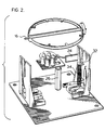
- This invention relates to a display element designed to provide a bright or dark appearance either as a single element or as a pixel in an array, using a reed switch, and also relates to a reed switch control arrangement.
- the display elements with which the invention is concerned have a movable element movable relative to a stationary element between ON and OFF positions and in these positions to provide a bright area or a dark area, respectively, visible in the viewing direction.
- a permanent magnet is provided movable with the movable element.
- a switchable magnetic core is provided on the stationary element located and adapted in one and the other polarity to cooperate with the permanent magnet to move the movable element to ON and OFF position, respectively.
- the core is of a high remanence material surrounded by an energizing winding which may be pulsed by an energizing current to switch the core polarity in an interval much less than the interval for the movable element to move between ON and OFF position.
- this invention is particularly concerned with display elements as above defined where the display of the bright area in the viewing direction in the ON position is augmented by a luminous source such as a light emitting diode ('LED') or an optic fibre and where such source must be turned off or masked from the viewer in the OFF position.
- a luminous source such as a light emitting diode ('LED') or an optic fibre
- An example of such display element using an optic fibre is US-A-4,833,806 to Jacques Le Gars, dated May 30, 1989, Assigned to Societe D'Etudes Pour Le Developpement.
- the back lighting is provided as an alternative for night use and is not used to augment the disk display.
- the light source only illuminates the display during night time when the disks are in midway positions. After dawn the light source is switched off and the moveable elements display either the light (ON) side or dark (OFF) side and do not adopt the midway position.
- the light source is never on when the reflecting, light coloured, (ON) side of the disk is displayed. Nor is the status of the illumination dependant upon the state of the disk in an individual pixel of the display.
- Such light-augmented element is particularly useful with 'writable' highway signs which are adapted to be read from some distance.
- Such signs will be formed of an array of display elements acting as pixels individually selectively switchable to display light or dark areas collectively providing informatio to the motorist.
- the luminous source be focussed to a beam about the viewing direction narrower than the viewing cone of the element as a whole to attract the driver's attention so that he, then, looks at the display as a whole, obtaining the information it displays from the collective effect of both its bright areas and dark areas with the bright areas augmented by the luminous sources in each pixel.
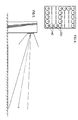
- the display element which is light-augmented in its ON position, defines a viewing cone centred about a viewing direction which viewing cone may have an apex angle larger than 90° and where within the cone there is a smaller focussed light beam cone when the element is ON with an apex angle of about 15° within the viewing cone.
- the first and second cores are approximately parallel and located and adapted so that when both cores have similar polarity the collective return flux of the two cores causes the switch to assume one state and when the two cores have opposite polarities causes the switch to assume the other state.
- the switch is connected so that one state turns on or exposes the light source and the other state turns off or masks the light source.
- the masking of the light source requires either 180° rotation of the disk or the presence of a special masking addition to the disk.
- the 180° rotation reduces the strength of the magnetic drive while the masking addition adds to the cost of the disk.
- the reed switch controlled by the switchable core provides a easy control for switching ON and OFF a light source such as an incandescent lamp or light emitting diode ('LED').
- a light source such as an incandescent lamp or light emitting diode ('LED').
- the reed switch may be connected to operate a shutter in the optic path, which includes the fibre, or, if the fibre has an individual light source may switch ON and OFF that source like the lamp or LED in the previous example.
- the reed switch controlled by the switchable core may be used for other purposes than control of the light source or light path.
- the reed-switched line may be used to signal the magnetic core state back to a scanner or control.
- the controlled reed switch could be used for other purposes, such as driving a slave display, of the same or different type.
Landscapes
- Physics & Mathematics (AREA)
- General Physics & Mathematics (AREA)
- Engineering & Computer Science (AREA)
- Theoretical Computer Science (AREA)
- Devices For Indicating Variable Information By Combining Individual Elements (AREA)
- Illuminated Signs And Luminous Advertising (AREA)
- Road Signs Or Road Markings (AREA)
- Circuit Arrangement For Electric Light Sources In General (AREA)
- Switches That Are Operated By Magnetic Or Electric Fields (AREA)
Claims (11)
- Un dispositif d'affichage comprenant :un élément mobile (18) et un élément fixe (14A,14B),ledit élément mobile (18) étant monté sur ledit élément fixe (14A,14B) afin d'effectuer un mouvement entre :une position MARCHE dans laquelle se trouve affichée une surface claire (22A) sur toute une zone située dans une direction de visée ; etune position ARRET,un moyen, adapté dans la position ARRET dudit élément mobile pour faire en sorte que ladite zone apparaisse sombre (22B) dans la direction de visée,un aimant permanent (28) capable de déplacement avec ledit élément mobile (20),un premier noyau magnétique à haute rémanence (30) adapté pour coopérer avec ledit aimant permanent (28) pour déplacer ledit élément mobile (18) vers les positions MARCHE et ARRET, à l'une ou l'autre polarité, respectivement,un enroulement d'excitation (34) autour dudit noyau (30) adapté pour commuter la dite polarité,caractérisé par :un interrupteur à lames (44) situé dans le trajet du flux de retour du premier noyau (30),ledit interrupteur à lames (44) commandant les états ouvert et fermé d'un circuit électrique auquel il est connecté,un second noyau (46) environ parallèle audit premier noyau (30), situé de façon à ce que l'interrupteur à lames (44) se trouve dans le trajet du flux de retour provenant du second noyau (46), lesdits premier et second noyaux (30,46) et ledit interrupteur à lames (44) étant situés et orientés de telle sorte que dans ladite une et autre polarité dudit premier noyau (30), le flux de retour combiné desdits premier et second noyaux (30,46) est adapté pour placer ledit interrupteur à lames (44) dans l'un et l'autre états.
- Un dispositif d'affichage selon la revendication 1 dans lequel :une source lumineuse (42) est située afin de briller à partir de la dite zone dans ladite direction de visée,des moyens sont prévus répondant à l'état dudit interrupteur à lames servant à commuter la dite source lumineuse (42) sur MARCHE et ARRET en réponse à l'existence de l'un dit et l'autre dit état.
- Un dispositif d'affichage selon la revendication 2 dans lequel l'élément mobile (18) est un disque (16) capable de rotation environ sur son diamètre ; le disque (18) présente une ouverture (40) et ladite source lumineuse (42) est située pour briller à travers la dite ouverture (40) en position MARCHE dudit disque.
- Un dispositif d'affichage selon la revendication 2 ou la revendication 3 dans lequel la dite zone peut être vue à l'intérieur d'un cône relativement large autour de la direction de visée, et la dite source lumineuse (42) se trouve focalisée afin de définir un faisceau allant en rétrécissant à l'intérieur dudit cône.
- Un dispositif d'affichage selon la revendication 2, 3 ou 4 dans lequel la dite source lumineuse (42) est au moins une diode électroluminescente.
- Un dispositif d'affichage selon la revendication 2 dans lequel le dit interrupteur à lames (44) est adapté pour se fermer lorsque ledit premier noyau (30) est polarisé pour placer l'élément mobile (18) en position MARCHE, et ledit interrupteur à lames (44) est monté en série avec la dite source lumineuse (42).
- Un dispositif d'affichage selon l'une quelconque des revendications 3 à 5 dans lequel l'interrupteur à lames (44) est adapté pour se fermer lorsque ledit premier noyau (30) est polarisé pour placer l'élément mobile (18) en position MARCHE, et ledit interrupteur à lames (44) est monté en série avec la dite source lumineuse (42).
- Un dispositif d'affichage selon la revendication 1 dans lequel un second interrupteur à lames (44 - Figure 10) est prévu situé dans le trajet du flux de retour dudit premier noyau (30), et un troisième noyau (46 - Figure 10) est prévu environ parallèle audit premier noyau (30), et situé de manière à ce que ledit second interrupteur à lames (44 - Fig. 10) se trouve dans le trajet du flux de retour provenant dudit troisième noyau, lesdits premier et troisième noyaux (46) et ledit second interrupteur à lames (44) étant positionnés et orientés de manière à ce que dans l'une et l'autre polarité dudit premier noyau (30) le flux de retour combiné desdits premier et second noyaux (30, 46) est adapté pour placer ledit second interrupteur à lames (44) dans l'un et l'autre états.
- Un dispositif d'affichage selon la revendication 8 dans lequel lesdits second et troisième noyaux (46) sont polarisés de façon opposée.
- Un dispositif d'affichage comprenant :un élément mobile (18) et un élément fixe (14A,14B),ledit élement mobile (18) ayant une surface claire (22A) et une surface sombre (22B) et étant monté sur ledit élément fixe (14A,14B) afin d'effectuer un mouvement entre :une position MARCHE dans laquelle se trouve affichée la dite surface claire (22A), sur toute une zone dans une direction de visée,une position ARRET dans laquelle se trouve affichée la dite surface sombre (22B), sur une telle zone,un aimant permanent (28) capable de déplacement avec ledit élément mobile (18),un premier noyau magnétique à haute rémanence (30) adapté pour coopérer avec ledit aimant permanent (28) pour déplacer ledit élément mobile (18) vers les positions MARCHE et ARRET, dans l'une et l'autre polarité, respectivement,un enroulement d'excitation (34) autour dudit noyau, adapté pour commuter la dite polarité,au moins une source lumineuse (42),caractérisé en ce que :la dite source lumineuse (42) est une diode électroluminescente et est située pour accroître l'apparition dans la direction de visée de la dite surface claire (22A), lorsque ledit élément mobile (18) est en position de MARCHE,des moyens sont prévus pour actionner ladite diode électroluminescente (42) lorsque ledit élément mobile (18) se trouve dans la position MARCHE et pour éteindre la dite diode électroluminescente (42) lorsque ledit élément mobile (18) se trouve en position ARRET.
- Un dispositif d'affichage selon la revendication 10 dans lequel le dit élément mobile (18) est un disque (16) capable de rotation environ sur son diamètre ; le disque présente une ouverture (40) et la dite source lumineuse (42) est située pour briller à travers ladite ouverture (40) en position MARCHE dudit disque.
Applications Claiming Priority (2)
| Application Number | Priority Date | Filing Date | Title |
|---|---|---|---|
| US07/522,739 US5050325A (en) | 1990-05-14 | 1990-05-14 | Display indicator and reed switch |
| US522739 | 1990-05-14 |
Publications (3)
| Publication Number | Publication Date |
|---|---|
| EP0463725A2 EP0463725A2 (fr) | 1992-01-02 |
| EP0463725A3 EP0463725A3 (en) | 1992-07-29 |
| EP0463725B1 true EP0463725B1 (fr) | 1996-01-17 |
Family
ID=24082131
Family Applications (1)
| Application Number | Title | Priority Date | Filing Date |
|---|---|---|---|
| EP91304087A Expired - Lifetime EP0463725B1 (fr) | 1990-05-14 | 1991-05-07 | Dispositif d'affichage avec un interrupteur du type "Reed" |
Country Status (5)
| Country | Link |
|---|---|
| US (1) | US5050325A (fr) |
| EP (1) | EP0463725B1 (fr) |
| JP (1) | JP3205569B2 (fr) |
| CA (1) | CA2041375C (fr) |
| DE (1) | DE69116447T2 (fr) |
Cited By (1)
| Publication number | Priority date | Publication date | Assignee | Title |
|---|---|---|---|---|
| DE19802218B4 (de) * | 1998-01-22 | 2010-11-25 | Annax Anzeigesysteme Gmbh | Elektromagnetische Anzeigevorrichtung |
Families Citing this family (16)
| Publication number | Priority date | Publication date | Assignee | Title |
|---|---|---|---|---|
| US5325108A (en) * | 1990-03-02 | 1994-06-28 | Unisplay S.A. | Information displays |
| US5337077A (en) * | 1992-03-20 | 1994-08-09 | Mark Iv Industries Limited | Electromagnetic shutter |
| US5793343A (en) * | 1994-10-27 | 1998-08-11 | American Signal Company | Display apparatus for signage |
| US5642130A (en) * | 1995-01-17 | 1997-06-24 | Mark Iv Industries Limited | Display array and power control circuit |
| US5898418A (en) * | 1995-03-06 | 1999-04-27 | Kao; Pin-Chi | Magnetically operated display |
| EP0731435B1 (fr) * | 1995-03-08 | 1999-01-27 | Lite Vision Corporation | Dispositif d'affichage à commande magnétique |
| FR2731828B1 (fr) * | 1995-03-17 | 1997-06-06 | Jc Decaux | Cellule elementaire d'affichage a pastille pivotante pour panneau d'affichage a matrices de points |
| US5771616C1 (en) * | 1996-07-19 | 2001-07-03 | Mark Iv Ind Ltd | Display device with disk and led |
| WO1997033266A1 (fr) * | 1996-03-05 | 1997-09-12 | Mark Iv Industries Limited | Dispositif et ensemble d'affichage |
| CA2171054C (fr) * | 1996-03-05 | 1999-05-25 | Veso S. Tijanic | Dispositif d'affichage disque lumineux |
| US6278431B1 (en) * | 1996-11-18 | 2001-08-21 | Lite Vision Corporation | Magnetically operated display |
| FR2761189B1 (fr) * | 1997-03-21 | 1999-06-04 | J C Decaux International | Panneau d'affichage de messages a matrices de points |
| DE59802569D1 (de) | 1997-09-30 | 2002-01-31 | Transit Media Gmbh Systemtechn | Montage von kippsegmentanzeigen hinter scheiben |
| US6603458B1 (en) * | 1998-01-22 | 2003-08-05 | Annex Anzeignsysteme Gmbh | Electromagnetic display device |
| FR2824173B1 (fr) * | 2001-03-09 | 2003-12-05 | Centaure Stystems | Dispositif d'affichage a pixels mecaniques eclaires |
| AT414165B (de) * | 2001-10-09 | 2006-09-15 | Gifas Electric Ges M B H | Leuchte |
Family Cites Families (6)
| Publication number | Priority date | Publication date | Assignee | Title |
|---|---|---|---|---|
| US3991496A (en) * | 1975-07-31 | 1976-11-16 | Ferranti-Packard Limited | Gravity bias for display elements |
| IT1076017B (it) * | 1977-02-01 | 1985-04-22 | Nuovo Pignone Spa | Perfezionamenti in un indicatore numerico elettromeccanico a sette segmenti |
| FR2585164B1 (fr) * | 1985-07-22 | 1988-04-22 | Soc Et Dev Prod Electron | Cellule elementaire d'affichage pour panneau d'affichage a matrice de points |
| DE3633957C1 (de) * | 1986-10-06 | 1988-02-18 | Herbert Graf | Vorrichtung zur Verkehrsregelung von Strassenfahrzeugen |
| US4914427A (en) * | 1988-11-03 | 1990-04-03 | The Staver Company Inc. | Matrix display system and method |
| US4974353A (en) * | 1989-08-28 | 1990-12-04 | The Staver Company | Matrix display assembly having multiple point lighting |
-
1990
- 1990-05-14 US US07/522,739 patent/US5050325A/en not_active Expired - Lifetime
-
1991
- 1991-04-26 CA CA002041375A patent/CA2041375C/fr not_active Expired - Fee Related
- 1991-05-07 EP EP91304087A patent/EP0463725B1/fr not_active Expired - Lifetime
- 1991-05-07 DE DE69116447T patent/DE69116447T2/de not_active Expired - Fee Related
- 1991-05-10 JP JP13571891A patent/JP3205569B2/ja not_active Expired - Fee Related
Cited By (1)
| Publication number | Priority date | Publication date | Assignee | Title |
|---|---|---|---|---|
| DE19802218B4 (de) * | 1998-01-22 | 2010-11-25 | Annax Anzeigesysteme Gmbh | Elektromagnetische Anzeigevorrichtung |
Also Published As
| Publication number | Publication date |
|---|---|
| DE69116447T2 (de) | 1996-08-08 |
| US5050325A (en) | 1991-09-24 |
| DE69116447D1 (de) | 1996-02-29 |
| JPH04229893A (ja) | 1992-08-19 |
| EP0463725A3 (en) | 1992-07-29 |
| EP0463725A2 (fr) | 1992-01-02 |
| CA2041375C (fr) | 1999-02-16 |
| CA2041375A1 (fr) | 1991-11-15 |
| JP3205569B2 (ja) | 2001-09-04 |
Similar Documents
| Publication | Publication Date | Title |
|---|---|---|
| EP0463725B1 (fr) | Dispositif d'affichage avec un interrupteur du type "Reed" | |
| US4694599A (en) | Electromagnetic flip-type visual indicator | |
| CA2013663C (fr) | Element d'affichage a disque encoche | |
| US3469258A (en) | Rotating magnetically actuated display or indicator | |
| JPS6158835B2 (fr) | ||
| US4295127A (en) | Information display device | |
| US5642130A (en) | Display array and power control circuit | |
| US4914427A (en) | Matrix display system and method | |
| US4794391A (en) | Display matrix incorporating light-conducting fibers and light-occulting shutters | |
| US6278431B1 (en) | Magnetically operated display | |
| EP0349109B1 (fr) | Dispositif d'affichage | |
| CA2087234C (fr) | Disque decoupe | |
| US6181315B1 (en) | Magnetically operated display | |
| EP0885437B1 (fr) | Dispositif et ensemble d'affichage | |
| US4558529A (en) | Display element with back lighting | |
| US6603458B1 (en) | Electromagnetic display device | |
| CA1205932A (fr) | Element electromecanique distinct, et grand panneau publicitaire | |
| US4811008A (en) | Color pigment graphics information display | |
| US5555339A (en) | Display matrix comprising light-emitting fibers that are maskable by disks each having a plurality of sectors | |
| US3368216A (en) | Rotatable drum indicator with electromagnetic drum control | |
| US4949082A (en) | High speed display device | |
| EP0068726A1 (fr) | Panneau d'affichage | |
| US5721564A (en) | Electromagnetically operated linearly sliding shutter for a variable display | |
| EP1591985A2 (fr) | Dispositif d'affichage électromagnétique | |
| RU2025789C1 (ru) | Индикатор |
Legal Events
| Date | Code | Title | Description |
|---|---|---|---|
| PUAI | Public reference made under article 153(3) epc to a published international application that has entered the european phase |
Free format text: ORIGINAL CODE: 0009012 |
|
| AK | Designated contracting states |
Kind code of ref document: A2 Designated state(s): DE DK ES FR GB IT SE |
|
| PUAL | Search report despatched |
Free format text: ORIGINAL CODE: 0009013 |
|
| AK | Designated contracting states |
Kind code of ref document: A3 Designated state(s): DE DK ES FR GB IT SE |
|
| 17P | Request for examination filed |
Effective date: 19920908 |
|
| 17Q | First examination report despatched |
Effective date: 19940211 |
|
| RAP1 | Party data changed (applicant data changed or rights of an application transferred) |
Owner name: MARK IV INDUSTRIES LIMITED |
|
| GRAA | (expected) grant |
Free format text: ORIGINAL CODE: 0009210 |
|
| AK | Designated contracting states |
Kind code of ref document: B1 Designated state(s): DE DK ES FR GB IT SE |
|
| PG25 | Lapsed in a contracting state [announced via postgrant information from national office to epo] |
Ref country code: DK Effective date: 19960117 |
|
| ITF | It: translation for a ep patent filed | ||
| REF | Corresponds to: |
Ref document number: 69116447 Country of ref document: DE Date of ref document: 19960229 |
|
| PG25 | Lapsed in a contracting state [announced via postgrant information from national office to epo] |
Ref country code: SE Effective date: 19960417 |
|
| PG25 | Lapsed in a contracting state [announced via postgrant information from national office to epo] |
Ref country code: ES Free format text: LAPSE BECAUSE OF FAILURE TO SUBMIT A TRANSLATION OF THE DESCRIPTION OR TO PAY THE FEE WITHIN THE PRESCRIBED TIME-LIMIT Effective date: 19960428 |
|
| ET | Fr: translation filed | ||
| PGFP | Annual fee paid to national office [announced via postgrant information from national office to epo] |
Ref country code: SE Payment date: 19960517 Year of fee payment: 6 |
|
| PLBE | No opposition filed within time limit |
Free format text: ORIGINAL CODE: 0009261 |
|
| STAA | Information on the status of an ep patent application or granted ep patent |
Free format text: STATUS: NO OPPOSITION FILED WITHIN TIME LIMIT |
|
| 26N | No opposition filed | ||
| PGFP | Annual fee paid to national office [announced via postgrant information from national office to epo] |
Ref country code: ES Payment date: 19970523 Year of fee payment: 7 |
|
| REG | Reference to a national code |
Ref country code: GB Ref legal event code: IF02 |
|
| PGFP | Annual fee paid to national office [announced via postgrant information from national office to epo] |
Ref country code: GB Payment date: 20030604 Year of fee payment: 13 |
|
| PGFP | Annual fee paid to national office [announced via postgrant information from national office to epo] |
Ref country code: DE Payment date: 20030605 Year of fee payment: 13 |
|
| PGFP | Annual fee paid to national office [announced via postgrant information from national office to epo] |
Ref country code: FR Payment date: 20030610 Year of fee payment: 13 |
|
| PG25 | Lapsed in a contracting state [announced via postgrant information from national office to epo] |
Ref country code: GB Free format text: LAPSE BECAUSE OF NON-PAYMENT OF DUE FEES Effective date: 20040507 |
|
| PG25 | Lapsed in a contracting state [announced via postgrant information from national office to epo] |
Ref country code: DE Free format text: LAPSE BECAUSE OF NON-PAYMENT OF DUE FEES Effective date: 20041201 |
|
| GBPC | Gb: european patent ceased through non-payment of renewal fee |
Effective date: 20040507 |
|
| PG25 | Lapsed in a contracting state [announced via postgrant information from national office to epo] |
Ref country code: FR Free format text: LAPSE BECAUSE OF NON-PAYMENT OF DUE FEES Effective date: 20050131 |
|
| REG | Reference to a national code |
Ref country code: FR Ref legal event code: ST |
|
| PG25 | Lapsed in a contracting state [announced via postgrant information from national office to epo] |
Ref country code: IT Free format text: LAPSE BECAUSE OF NON-PAYMENT OF DUE FEES;WARNING: LAPSES OF ITALIAN PATENTS WITH EFFECTIVE DATE BEFORE 2007 MAY HAVE OCCURRED AT ANY TIME BEFORE 2007. THE CORRECT EFFECTIVE DATE MAY BE DIFFERENT FROM THE ONE RECORDED. Effective date: 20050507 |