EP0464257B1 - Centrifugeuse à mouvements multiples - Google Patents
Centrifugeuse à mouvements multiples Download PDFInfo
- Publication number
- EP0464257B1 EP0464257B1 EP90121265A EP90121265A EP0464257B1 EP 0464257 B1 EP0464257 B1 EP 0464257B1 EP 90121265 A EP90121265 A EP 90121265A EP 90121265 A EP90121265 A EP 90121265A EP 0464257 B1 EP0464257 B1 EP 0464257B1
- Authority
- EP
- European Patent Office
- Prior art keywords
- cam
- rotation
- rotor
- clutch
- drive shaft
- Prior art date
- Legal status (The legal status is an assumption and is not a legal conclusion. Google has not performed a legal analysis and makes no representation as to the accuracy of the status listed.)
- Expired - Lifetime
Links
- 230000033001 locomotion Effects 0.000 title claims abstract description 19
- 238000013019 agitation Methods 0.000 claims abstract description 15
- 230000002441 reversible effect Effects 0.000 claims description 8
- 239000012530 fluid Substances 0.000 claims description 6
- 210000001519 tissue Anatomy 0.000 description 10
- 210000004027 cell Anatomy 0.000 description 5
- 238000005119 centrifugation Methods 0.000 description 4
- 210000004925 microvascular endothelial cell Anatomy 0.000 description 4
- 230000029087 digestion Effects 0.000 description 3
- 238000006073 displacement reaction Methods 0.000 description 3
- 210000002889 endothelial cell Anatomy 0.000 description 3
- 238000003756 stirring Methods 0.000 description 3
- 239000007943 implant Substances 0.000 description 2
- 238000002513 implantation Methods 0.000 description 2
- 238000000034 method Methods 0.000 description 2
- 239000008188 pellet Substances 0.000 description 2
- 238000000926 separation method Methods 0.000 description 2
- 102000029816 Collagenase Human genes 0.000 description 1
- 108060005980 Collagenase Proteins 0.000 description 1
- 102000035195 Peptidases Human genes 0.000 description 1
- 108091005804 Peptidases Proteins 0.000 description 1
- 102000004142 Trypsin Human genes 0.000 description 1
- 108090000631 Trypsin Proteins 0.000 description 1
- 210000002565 arteriole Anatomy 0.000 description 1
- 239000008280 blood Substances 0.000 description 1
- 210000004369 blood Anatomy 0.000 description 1
- 210000001124 body fluid Anatomy 0.000 description 1
- 239000010839 body fluid Substances 0.000 description 1
- 210000001736 capillary Anatomy 0.000 description 1
- 239000000969 carrier Substances 0.000 description 1
- 238000006243 chemical reaction Methods 0.000 description 1
- 229960002424 collagenase Drugs 0.000 description 1
- 230000007423 decrease Effects 0.000 description 1
- 230000003247 decreasing effect Effects 0.000 description 1
- 238000000151 deposition Methods 0.000 description 1
- 201000010099 disease Diseases 0.000 description 1
- 208000037265 diseases, disorders, signs and symptoms Diseases 0.000 description 1
- 238000002474 experimental method Methods 0.000 description 1
- 238000002955 isolation Methods 0.000 description 1
- 210000004924 lung microvascular endothelial cell Anatomy 0.000 description 1
- 239000000463 material Substances 0.000 description 1
- 210000004088 microvessel Anatomy 0.000 description 1
- 230000000877 morphologic effect Effects 0.000 description 1
- 210000003200 peritoneal cavity Anatomy 0.000 description 1
- 238000004393 prognosis Methods 0.000 description 1
- 238000004062 sedimentation Methods 0.000 description 1
- 210000004003 subcutaneous fat Anatomy 0.000 description 1
- 239000000725 suspension Substances 0.000 description 1
- 210000000115 thoracic cavity Anatomy 0.000 description 1
- 239000012588 trypsin Substances 0.000 description 1
- 210000000264 venule Anatomy 0.000 description 1
Images


Classifications
-
- B—PERFORMING OPERATIONS; TRANSPORTING
- B01—PHYSICAL OR CHEMICAL PROCESSES OR APPARATUS IN GENERAL
- B01F—MIXING, e.g. DISSOLVING, EMULSIFYING OR DISPERSING
- B01F31/00—Mixers with shaking, oscillating, or vibrating mechanisms
- B01F31/60—Mixers with shaking, oscillating, or vibrating mechanisms with a vibrating receptacle
-
- B—PERFORMING OPERATIONS; TRANSPORTING
- B04—CENTRIFUGAL APPARATUS OR MACHINES FOR CARRYING-OUT PHYSICAL OR CHEMICAL PROCESSES
- B04B—CENTRIFUGES
- B04B5/00—Other centrifuges
- B04B5/04—Radial chamber apparatus for separating predominantly liquid mixtures, e.g. butyrometers
- B04B5/0407—Radial chamber apparatus for separating predominantly liquid mixtures, e.g. butyrometers for liquids contained in receptacles
- B04B5/0414—Radial chamber apparatus for separating predominantly liquid mixtures, e.g. butyrometers for liquids contained in receptacles comprising test tubes
- B04B5/0421—Radial chamber apparatus for separating predominantly liquid mixtures, e.g. butyrometers for liquids contained in receptacles comprising test tubes pivotably mounted
-
- B—PERFORMING OPERATIONS; TRANSPORTING
- B04—CENTRIFUGAL APPARATUS OR MACHINES FOR CARRYING-OUT PHYSICAL OR CHEMICAL PROCESSES
- B04B—CENTRIFUGES
- B04B9/00—Drives specially designed for centrifuges; Arrangement or disposition of transmission gearing; Suspending or balancing rotary bowls
-
- B—PERFORMING OPERATIONS; TRANSPORTING
- B04—CENTRIFUGAL APPARATUS OR MACHINES FOR CARRYING-OUT PHYSICAL OR CHEMICAL PROCESSES
- B04B—CENTRIFUGES
- B04B9/00—Drives specially designed for centrifuges; Arrangement or disposition of transmission gearing; Suspending or balancing rotary bowls
- B04B9/08—Arrangement or disposition of transmission gearing ; Couplings; Brakes
Definitions
- this invention relates to a device for imparting centrifugal force to samples in order to separate a heavier and a lighter fraction in each of the samples. More particularly, this invention relates to a device which may utilize both an agitating vertical movement to impart a stirring action to a sample, followed by a centrifugal force applied to the sample.
- the device of the invention utilizes a single drive for this purpose.
- US-A-3 980 227 discloses a rotator for mildly agitating or mildly centrifuging a plurality of fluid samples in the laboratory. Samples which are to be processed or analyzed in the laboratory are placed in small vials or cuvettes. Groups of cuvettes are placed in arcuate carriers, which are then mounted about the periphery of a rotator head.
- the rotator head has two selectable motions. It can rotate at a higher speed on a vertical axis for an automatically timed period, thereby subjecting the samples to mild centrifugal settling or sedimentation, or it can rotate at a lower speed about an inclined axis, thereby subjecting the sample to mild agitation or mixing.
- microvascular endothelial cells i.e., the cells which are derived from capillaries, arterioles, and venules, will function suitably in place of large vessel cells even though there are morphological and functional differences between large vessel endothelial cells and microvascular endothelial cells in their native tissues.
- Microvascular endothelial cells are present in an abundant supply in body tissue, most notably in fat tissue, and may be used to established a degree of pre-implantation confluence, i.e., at least fifty percent, which should dramatically improve the prognosis of most implants.
- fat tissue may be taken from a patient in the environment of an operating room, and that fat tissue acted upon in order to obtain microvascular endothelial cells which may be then implanted on the surface of synthetic grafts which are implanted to substitute for the natural blood carrying vessels in the body.
- microvessel endothelial cells have been shown to be capable of endothelializing a blood-contacting surface, methods of procuring and depositing these cells in an operating room setting present special considerations.
- the microvascular-rich tissue is obtained in perinephric fat, subcutaneous fat, or fat associated with the thoracic or peritoneal cavity. This tissue is then subjected to digestion using a proteolytic enzyme, such as collagenase, comprising caseanase and trypsin, which is incubated with the tissue until the tissue mass disperses to reduce a tissue digest. It is during this period, that the invention may be utilized in order to agitate this combination to obtain a certain result. Thereafter, the microvascular endothelial cells are then separated from the digest that has already taken place using centrifugation to produce an endothelial cell-rich pellet. The pellet may then be dissolved in an appropriate suspension and the resulting cells applied to the surface of a graft. As a result, an improved graft implant is provided having endothelialized surfaces which are either confluent or which reach confluence quite rapidly (within one population doubling) following implantation.
- a proteolytic enzyme such as collagenase, compris
- a special feature of the invention here, as stated above, is that the device of the invention allows digestion with agitation followed by centrifugation, with these movements being selected, as desired in the controls of the single device of the invention. It will be understood, however, that the environment discussed above is not the only environment in which the device of the invention may be used. It may be used, as will be apparent to practitioners-in-the-art, in any application where agitation movement may be required selectively with centrifugation, as required in any process.
- Fig. 1 shows a view in elevation and partly in section of a device designated generally 10 which provides for the selective impartation to samples of an agitation and/or stirring movement or centrifugal forces applied to the samples.
- a reversible electric motor 12 having a drive shaft 14 extending therefrom.
- drive shaft 14 Positioned on drive shaft 14 are spaced apart roller clutches 18, 20 with one mounted for movement with shaft 14 in one direction while the other is mounted for rotation with shaft 14 in the opposite direction.
- clutches 18, 20 rotate freely on shaft 14 in the opposite direction of their positive drive rotation with shaft 14.
- Clutch 18 is connected to cylindrical cam 22, while clutch 20 is connected to rotor 16.
- each end 36, 40, of rotor 16 Mounted on each end 36, 40, of rotor 16 are sample containing receptacles 30, 32 rotatable around pivots 38, 34, respectively.
- the rotor 16 has a bore 46 therein for receiving a movable rod 44 movable vertically into and out of bore 46 under the action of a solenoid 42.
- Both electric motor 12 and solenoid 42 are operated from a power source 56 through lines 60 to a control 58.
- Control 58 controls the on and off and reverse action of motor 12 through line 62, while control 58 controls the action of solenoid 42 through line 64.
- clutch 20 grips the shaft 14 and rotates with the shaft 14. In this position, solenoid 42 will be set to withdraw the rod 44 out of the bore 46.
- the rotor 16 rotates around axis 15 causing the opposite ends 36, 40 of rotor 16 to rotate around axis 15.
- This rotation imparts centrifugal force and causes the sample receptacles 30, 32 to swing around axis 15, which in turn causes them to pivot around their respective pivots 38, 34 so that the samples placed in receptacles 30, 32 have imparted to them centrifugal force.
- clutch 18 allows shaft 14 to rotate freely within it since it is arranged to grip shaft 14 in the opposite direction.
- This rotating movement in one direction causing rotor 16 to rotate around axis 15 also causes vertical annular cam support 24 to rotate around axis 15 in the same direction, together with cam follower 28 and cam 22.
- control 58 When it is desired to impart an agitation form of vertical movement to samples contained in receptacles 30, 32, control 58 is set to reverse reversible motor 12 so that shaft 14 is rotated in the opposite direction. Prior to this movement of motor 12 and shaft 14, however, solenoid 42 is activated to cause rod 44 to move upwardly into bore 46. The positioning of rotor 16 may need adjustment for this purpose. Such an arrangement fixes rotor 16 in place. This, in turn, fixes annular cylinder cam support 24 in place together with cam follower 28. Thus, none of these parts rotate around axis 15.
- the amount of vertical movement 66 depends upon the particular cam profile selected. Moreover, the sequence of movement relative to the circular movement of cylinder cam 22 is also defined by the cam profile.
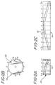
- cam groove 70 in viewing one side of cam 22, has a particular slope which slopes from an upward position at angle 6 to a very low position in the side of the cam at position 0.
- the actual profile of groove 70 in cam 22 is shown at 74 in Fig. 2c.
- Each individual position 72 such as 1, 2 and 3, in this particular cam profile, provides a 30 degree rotational displacement, as will be understood by practitioners-in-the-art.
- a cam 76 is shown in side elevation.
- groove 78 follows a different path around cylinder cam 76.
- profile 80 in Fig. 3c cam groove 78 follows an undulating path which has a lesser degree of vertical displacement than groove 70 shown in Fig. 2c.
- Such an arrangement provides a lesser degree of vertical displacement of the samples under consideration and less, but more rapid, agitation, for a given motor shaft rotation.
- such an arrangement provides a means for imparting the desired characteristics to a particular sample without having to transfer the sample from one place to another. This reduces the amount of equipment required for cell digestion, isolation experiments. This is particularly appropriate in an operating room environment, as discussed above, because the treatment of the samples, as required, may be done much more rapidly and because of a desired sterile environment, much less transfer and handling of the sample is required.
- control for the reversible motor may have incorporated therein a speed mechanism for increasing or reducing the speed of rotation of the device of the invention. This, in turn, increases or decreases the speed of agitation or the speed of rotation for increasing or decreasing the centrifugal force applied.
Landscapes
- Chemical & Material Sciences (AREA)
- Chemical Kinetics & Catalysis (AREA)
- Centrifugal Separators (AREA)
- Sampling And Sample Adjustment (AREA)
- Jigging Conveyors (AREA)
- Acyclic And Carbocyclic Compounds In Medicinal Compositions (AREA)
- Coloring Foods And Improving Nutritive Qualities (AREA)
Claims (6)
- Dispositif pour appliquer séquentiellement une force centrifuge ou une agitation à un échantillon de fluide placé dans le dispositif, comprenant
une source d'énergie (56);
des moyens formant moteur rotatif (12);
des moyens de transmission d'énergie (62) s'étendant entre ladite source d'énergie (56) et lesdits moyens formant moteur rotatif (12);
des moyens de commande (58) situés dans lesdits moyens de transmission d'énergie pour commander la rotation desdits moyens formant moteur rotatif (12);
un arbre d'entraînement (14) qui s'étend à partir desdits moyens formant moteur (12);
un rotor (16) raccordé audit arbre d'entraînement (14) de manière à pouvoir tourner avec celui-ci; et
des moyens (30,32) pour supporter des échantillons de fluide sur chaque extrémité (36) dudit rotor (16),
caractérisé en ce que
lesdits moyens formant moteur (12) sont réversibles et lesdits moyens de transmission d'énergie (62) commandent le sens desdits moyens formant moteur réversible (12);
un premier embrayage (20) est monté sur ledit arbre d'entraînement (14), ledit premier embrayage étant fixé pour être entraîné avec ledit arbre d'entraînement dans un premier sens, et pouvant tourner librement sur ledit arbre dans un second sens;
un second embrayage (18) est monté sur ledit arbre d'entraînement (14), ledit second embrayage pouvant tourner librement sur ledit arbre d'entraînement dans ledit premier sens, et étant bloqué en rotation sur ledit arbre dans ledit second sens;
ledit rotor (16) étant raccordé audit premier embrayage (20);
un suiveur de came (28) est monté de manière à tourner avec ledit rotor (16);
une came (22) est raccordée audit second embrayage (18); des moyens (44) sont raccordés auxdits moyens de commande (58) et sont déplaçables de manière à empêcher une rotation dudit rotor (16) avec ledit premier embrayage (20) dans ledit second sens de rotation. - Dispositif selon la revendication 1, dans lequel, en outre,
ledit rotor (16) est un support allongé pouvant tourner autour de l'axe (15) dudit arbre d'entraînement (14); et lesdits moyens (30,32) servant à supporter des échantillons de fluide sont des récipients montés pivotants sur chaque extrémité dudit rotor allongé (16) et supportés à égale distance dudit axe de rotation. - Dispositif selon la revendication 1, dans lequel, en outre,
un support annulaire de came (24) est fixé sur ledit rotor (16) et est coaxial audit arbre d'entraînement (14);
ladite came (22) est une came cylindrique supportée coaxialement de manière à tourner dans ledit support de came (24);
ladite came cylindrique possède une gorge de came (70) qui s'étend autour de sa circonférence extérieure;
ledit suiveur de came (28) est fixé sur la surface intérieure dudit support annulaire de came (24); et
ledit suiveur de came (28) pénètre dans ladite gorge de came (70), ce qui a pour effet qu'une rotation de ladite came cylindrique (22) provoque un déplacement vertical dudit support annulaire de came (24) et dudit rotor (16). - Dispositif selon la revendication 3, dans lequel
ladite gorge de came (70) possède un profil de forme ondulée qui s'étend le long de la surface de came centralement entre les surfaces supérieure et inférieure de ladite came cylindrique (22). - Dispositif selon la revendication 3, dans lequel
ladite gorge de came (70) possède un profil, selon lequel ladite gorge s'étend, en allant et venant, d'une position directement adjacente à la surface supérieure de ladite came cylindrique (22) à une position directement adjacente à la surface inférieure de cette came. - Dispositif selon la revendication 1, dans lequel, en outre,
lesdits moyens (44) pour empêcher une rotation dudit rotor consistent en une tige raccordée à un électroaimant (42) et déplaçable pour être amenée dans et dégagée d'une position empêchant une rotation dudit rotor avec ledit premier embrayage (20) dans ledit second sens de rotation.
Applications Claiming Priority (2)
| Application Number | Priority Date | Filing Date | Title |
|---|---|---|---|
| US547711 | 1990-07-02 | ||
| US07/547,711 US4990130A (en) | 1990-07-02 | 1990-07-02 | Multiple motion centrifuge |
Publications (2)
| Publication Number | Publication Date |
|---|---|
| EP0464257A1 EP0464257A1 (fr) | 1992-01-08 |
| EP0464257B1 true EP0464257B1 (fr) | 1995-03-01 |
Family
ID=24185820
Family Applications (1)
| Application Number | Title | Priority Date | Filing Date |
|---|---|---|---|
| EP90121265A Expired - Lifetime EP0464257B1 (fr) | 1990-07-02 | 1990-11-07 | Centrifugeuse à mouvements multiples |
Country Status (12)
| Country | Link |
|---|---|
| US (1) | US4990130A (fr) |
| EP (1) | EP0464257B1 (fr) |
| JP (1) | JPH0671567B2 (fr) |
| AT (1) | ATE119077T1 (fr) |
| AU (1) | AU622579B2 (fr) |
| BR (1) | BR9005757A (fr) |
| CA (1) | CA2029155C (fr) |
| DE (1) | DE69017444T2 (fr) |
| ES (1) | ES2069653T3 (fr) |
| IL (1) | IL96497A (fr) |
| MX (1) | MX171325B (fr) |
| ZA (1) | ZA908920B (fr) |
Families Citing this family (19)
| Publication number | Priority date | Publication date | Assignee | Title |
|---|---|---|---|---|
| JPH0427457A (ja) * | 1990-05-23 | 1992-01-30 | Matsushita Electric Ind Co Ltd | 遠心分離機および自動遠心分離装置 |
| US6478724B1 (en) | 1998-06-03 | 2002-11-12 | Jeffery N. Beattey | Centrifuge with clutch mechanism for synchronous blade and bowl rotation |
| US6224532B1 (en) * | 1998-06-03 | 2001-05-01 | Jeffery N. Beattey | Centrifuge blade design and control mechanism |
| FR2797202B1 (fr) * | 1999-08-02 | 2001-10-26 | Genomic | Equipement pour l'extraction automatique d'acides nucleiques |
| US6679385B2 (en) * | 2001-04-18 | 2004-01-20 | M I Llc. | Motor control system for vibrating screen separator |
| US6513664B1 (en) | 2001-04-18 | 2003-02-04 | M-I, L.L.C. | Vibrating screen separator |
| US7204637B2 (en) * | 2004-06-14 | 2007-04-17 | Michael Sherman | Automated device for homogenization and resuspension of substances, disintegration of cells, disruption of tissues and centrifugation of these media |
| WO2013113847A1 (fr) | 2012-01-31 | 2013-08-08 | Quantifoil Instruments Gmbh | Mécanisme à pignons permettant de générer un mouvement d'agitation orbital |
| GB2498953A (en) * | 2012-01-31 | 2013-08-07 | Quantifoil Instr Gmbh | Mechanism for orbital shaking motion |
| EP2809435B1 (fr) * | 2012-01-31 | 2016-04-06 | Quantifoil Instruments Gmbh | Mécanisme de génération d'un mouvement orbital ou d'un mouvement de rotation par inversion d'une direction d'entraînement d'une unité d'entraînement, appareil et procédé |
| GB2498957A (en) * | 2012-01-31 | 2013-08-07 | Quantifoil Instr Gmbh | Mechanism for switching between orbital shaking motion and centrifugal motion |
| US10239063B2 (en) | 2013-06-28 | 2019-03-26 | Quantifoil Instruments Gmbh | Application-specific sample processing by modules surrounding a rotor mechanism for sample mixing and sample separation |
| FR3007671B1 (fr) * | 2013-07-01 | 2015-07-17 | Chopin Technologies | Dispositif de secouage. |
| FR3007670B1 (fr) * | 2013-07-01 | 2017-01-06 | Chopin Tech | Dispositif de secouage et de centrifugation. |
| CN105115809B (zh) * | 2015-09-11 | 2017-07-28 | 北京本立科技有限公司 | 一种分析样品制备装置及分析样品制备方法 |
| CN107126882A (zh) * | 2017-06-29 | 2017-09-05 | 山东大农药业有限公司 | 颗粒物料搅拌装置 |
| CN108568349A (zh) * | 2018-04-10 | 2018-09-25 | 佛山市三水万瑞达环保科技有限公司 | 一种零件与油液分离装置 |
| CN108686562B (zh) * | 2018-08-10 | 2021-03-05 | 山东省肿瘤防治研究院(山东省肿瘤医院) | 一种可载药栓塞微球配置晃动器 |
| CN111744404A (zh) * | 2020-07-22 | 2020-10-09 | 兰州弘展信息科技有限公司 | 一种乳胶漆及其制备系统与制备方法 |
Family Cites Families (5)
| Publication number | Priority date | Publication date | Assignee | Title |
|---|---|---|---|---|
| US2494866A (en) * | 1947-08-19 | 1950-01-17 | Alfred J Fressola | Agitating device |
| US3980227A (en) * | 1974-11-08 | 1976-09-14 | Baxter Travenol Laboratories, Inc. | Adjustable rotator for fluid samples |
| US4659324A (en) * | 1984-06-04 | 1987-04-21 | Beckman Instruments, Inc. | Centrifuge rotor with an offset pivotal mount for a sample container |
| SE8404931L (sv) * | 1984-10-02 | 1985-08-26 | Peter Johan Torsten Tornqvist | Anordning for att mekaniskt sla sonder en barrier mellan blandbara ingredienser och blanda dessa |
| US4589864A (en) * | 1984-11-05 | 1986-05-20 | E. I. Du Pont De Nemours And Company | Centrifuge rotor having a resilient trunnion |
-
1990
- 1990-07-02 US US07/547,711 patent/US4990130A/en not_active Expired - Fee Related
- 1990-11-01 CA CA002029155A patent/CA2029155C/fr not_active Expired - Fee Related
- 1990-11-05 AU AU65824/90A patent/AU622579B2/en not_active Ceased
- 1990-11-07 EP EP90121265A patent/EP0464257B1/fr not_active Expired - Lifetime
- 1990-11-07 ZA ZA908920A patent/ZA908920B/xx unknown
- 1990-11-07 DE DE69017444T patent/DE69017444T2/de not_active Expired - Fee Related
- 1990-11-07 ES ES90121265T patent/ES2069653T3/es not_active Expired - Lifetime
- 1990-11-07 AT AT90121265T patent/ATE119077T1/de active
- 1990-11-13 BR BR909005757A patent/BR9005757A/pt not_active Application Discontinuation
- 1990-11-19 MX MX023388A patent/MX171325B/es unknown
- 1990-11-28 IL IL9649790A patent/IL96497A/en not_active IP Right Cessation
- 1990-12-26 JP JP2406561A patent/JPH0671567B2/ja not_active Expired - Lifetime
Also Published As
| Publication number | Publication date |
|---|---|
| CA2029155A1 (fr) | 1992-01-03 |
| DE69017444D1 (de) | 1995-04-06 |
| AU622579B2 (en) | 1992-04-09 |
| ES2069653T3 (es) | 1995-05-16 |
| CA2029155C (fr) | 1994-09-20 |
| IL96497A0 (en) | 1991-08-16 |
| AU6582490A (en) | 1992-01-02 |
| ZA908920B (en) | 1991-08-28 |
| BR9005757A (pt) | 1992-04-21 |
| DE69017444T2 (de) | 1995-09-07 |
| MX171325B (es) | 1993-10-18 |
| EP0464257A1 (fr) | 1992-01-08 |
| IL96497A (en) | 1994-06-24 |
| ATE119077T1 (de) | 1995-03-15 |
| US4990130A (en) | 1991-02-05 |
| JPH04210264A (ja) | 1992-07-31 |
| JPH0671567B2 (ja) | 1994-09-14 |
Similar Documents
| Publication | Publication Date | Title |
|---|---|---|
| US4990130A (en) | Multiple motion centrifuge | |
| EP0740964B1 (fr) | Centrifugeuse pour décantation multiple automatique | |
| EP0853493B1 (fr) | Procede et appareil de melange par tourbillons sous l'effet d'une force centrifuge | |
| US4751357A (en) | Microwave oven with moving equipment, and an accessory for the oven | |
| USRE38730E1 (en) | Automatic multiple-decanting centrifuge and method of treating physiological fluids | |
| EP0421985B1 (fr) | Dispositif de melange d'au moins une substance aqueuse | |
| US3850369A (en) | Centrifuge for preparing platelet rich plasma | |
| EP0281321A3 (fr) | Procédé et appareil pour le traitement de fluides biologiques | |
| US4231403A (en) | Liquid feeder for automatic culture apparatus | |
| EP1314471A1 (fr) | Mélangeur de type disque-pale pour mélanger le contenu d'un récipient pendant l'extraction d'échantillon et procédé d'utilisation | |
| JP2007534000A (ja) | インビトロ試験中に試料を攪拌する装置および方法 | |
| US5167449A (en) | Paddle shaft assembly with adjustable-pitch paddles | |
| WO2005039773A1 (fr) | Contenant jetable pour centrifuger et pour traiter une matiere biologique fluide | |
| DE1598369A1 (de) | Zentrifuge zum Mischen und Dekantieren,insbesondere zur Blutprobenuntersuchung | |
| US20200289738A1 (en) | Centrifuge and method of use | |
| EP1321756A1 (fr) | Procede de preparation d'echantillons organiques ou inorganiques destines a un examen clinique ou scientifique et machine permettant de mettre en oeuvre ledit procede | |
| FR2624615B1 (fr) | Dispositif de presentation de recipients | |
| JP2010158203A (ja) | 撹拌機および細胞分離装置 | |
| WO1998032838A1 (fr) | Agitateur-secoueur | |
| CN108404763A (zh) | 一种液体自动混匀装置 | |
| WO1998006485A1 (fr) | Appareil agitateur | |
| CN115046840B (zh) | 一种使样本和溶液充分搅拌混合的方法 | |
| WO1997018022A3 (fr) | Ameliorations concernant des moteurs electriques et un appareil de centrifugation | |
| CN115228626B (zh) | 一种离心机及具有该离心机的全自动试验仪器 | |
| CN213791362U (zh) | 一种骨折断端血运输装置 |
Legal Events
| Date | Code | Title | Description |
|---|---|---|---|
| PUAI | Public reference made under article 153(3) epc to a published international application that has entered the european phase |
Free format text: ORIGINAL CODE: 0009012 |
|
| 17P | Request for examination filed |
Effective date: 19901206 |
|
| AK | Designated contracting states |
Kind code of ref document: A1 Designated state(s): AT BE CH DE DK ES FR GB GR IT LI LU NL SE |
|
| 17Q | First examination report despatched |
Effective date: 19930915 |
|
| GRAA | (expected) grant |
Free format text: ORIGINAL CODE: 0009210 |
|
| AK | Designated contracting states |
Kind code of ref document: B1 Designated state(s): AT BE CH DE DK ES FR GB GR IT LI LU NL SE |
|
| PG25 | Lapsed in a contracting state [announced via postgrant information from national office to epo] |
Ref country code: NL Free format text: LAPSE BECAUSE OF NON-PAYMENT OF DUE FEES Effective date: 19950301 Ref country code: LI Effective date: 19950301 Ref country code: GR Free format text: LAPSE BECAUSE OF FAILURE TO SUBMIT A TRANSLATION OF THE DESCRIPTION OR TO PAY THE FEE WITHIN THE PRESCRIBED TIME-LIMIT Effective date: 19950301 Ref country code: DK Effective date: 19950301 Ref country code: CH Effective date: 19950301 Ref country code: BE Effective date: 19950301 Ref country code: AT Effective date: 19950301 |
|
| REF | Corresponds to: |
Ref document number: 119077 Country of ref document: AT Date of ref document: 19950315 Kind code of ref document: T |
|
| REF | Corresponds to: |
Ref document number: 69017444 Country of ref document: DE Date of ref document: 19950406 |
|
| ET | Fr: translation filed | ||
| ITF | It: translation for a ep patent filed | ||
| REG | Reference to a national code |
Ref country code: ES Ref legal event code: FG2A Ref document number: 2069653 Country of ref document: ES Kind code of ref document: T3 |
|
| PG25 | Lapsed in a contracting state [announced via postgrant information from national office to epo] |
Ref country code: SE Effective date: 19950601 |
|
| REG | Reference to a national code |
Ref country code: CH Ref legal event code: PL |
|
| NLV1 | Nl: lapsed or annulled due to failure to fulfill the requirements of art. 29p and 29m of the patents act | ||
| PG25 | Lapsed in a contracting state [announced via postgrant information from national office to epo] |
Ref country code: GB Effective date: 19951107 |
|
| PG25 | Lapsed in a contracting state [announced via postgrant information from national office to epo] |
Ref country code: ES Free format text: LAPSE BECAUSE OF NON-PAYMENT OF DUE FEES Effective date: 19951108 |
|
| PG25 | Lapsed in a contracting state [announced via postgrant information from national office to epo] |
Ref country code: LU Free format text: LAPSE BECAUSE OF NON-PAYMENT OF DUE FEES Effective date: 19951130 |
|
| PLBE | No opposition filed within time limit |
Free format text: ORIGINAL CODE: 0009261 |
|
| STAA | Information on the status of an ep patent application or granted ep patent |
Free format text: STATUS: NO OPPOSITION FILED WITHIN TIME LIMIT |
|
| 26N | No opposition filed | ||
| GBPC | Gb: european patent ceased through non-payment of renewal fee |
Effective date: 19951107 |
|
| PG25 | Lapsed in a contracting state [announced via postgrant information from national office to epo] |
Ref country code: FR Effective date: 19960731 |
|
| PG25 | Lapsed in a contracting state [announced via postgrant information from national office to epo] |
Ref country code: DE Effective date: 19960801 |
|
| REG | Reference to a national code |
Ref country code: FR Ref legal event code: ST |
|
| REG | Reference to a national code |
Ref country code: ES Ref legal event code: FD2A Effective date: 19961213 |
|
| PG25 | Lapsed in a contracting state [announced via postgrant information from national office to epo] |
Ref country code: IT Free format text: LAPSE BECAUSE OF NON-PAYMENT OF DUE FEES;WARNING: LAPSES OF ITALIAN PATENTS WITH EFFECTIVE DATE BEFORE 2007 MAY HAVE OCCURRED AT ANY TIME BEFORE 2007. THE CORRECT EFFECTIVE DATE MAY BE DIFFERENT FROM THE ONE RECORDED. Effective date: 20051107 |