EP0464481B1 - Dispositif de commande d'un moteur hydraulique - Google Patents
Dispositif de commande d'un moteur hydraulique Download PDFInfo
- Publication number
- EP0464481B1 EP0464481B1 EP91110125A EP91110125A EP0464481B1 EP 0464481 B1 EP0464481 B1 EP 0464481B1 EP 91110125 A EP91110125 A EP 91110125A EP 91110125 A EP91110125 A EP 91110125A EP 0464481 B1 EP0464481 B1 EP 0464481B1
- Authority
- EP
- European Patent Office
- Prior art keywords
- valve
- line
- cylinder
- cylinder space
- pressure
- Prior art date
- Legal status (The legal status is an assumption and is not a legal conclusion. Google has not performed a legal analysis and makes no representation as to the accuracy of the status listed.)
- Expired - Lifetime
Links
Images

Classifications
-
- F—MECHANICAL ENGINEERING; LIGHTING; HEATING; WEAPONS; BLASTING
- F15—FLUID-PRESSURE ACTUATORS; HYDRAULICS OR PNEUMATICS IN GENERAL
- F15B—SYSTEMS ACTING BY MEANS OF FLUIDS IN GENERAL; FLUID-PRESSURE ACTUATORS, e.g. SERVOMOTORS; DETAILS OF FLUID-PRESSURE SYSTEMS, NOT OTHERWISE PROVIDED FOR
- F15B11/00—Servomotor systems without provision for follow-up action; Circuits therefor
- F15B11/08—Servomotor systems without provision for follow-up action; Circuits therefor with only one servomotor
-
- F—MECHANICAL ENGINEERING; LIGHTING; HEATING; WEAPONS; BLASTING
- F15—FLUID-PRESSURE ACTUATORS; HYDRAULICS OR PNEUMATICS IN GENERAL
- F15B—SYSTEMS ACTING BY MEANS OF FLUIDS IN GENERAL; FLUID-PRESSURE ACTUATORS, e.g. SERVOMOTORS; DETAILS OF FLUID-PRESSURE SYSTEMS, NOT OTHERWISE PROVIDED FOR
- F15B2211/00—Circuits for servomotor systems
- F15B2211/30—Directional control
- F15B2211/305—Directional control characterised by the type of valves
- F15B2211/3056—Assemblies of multiple valves
- F15B2211/30565—Assemblies of multiple valves having multiple valves for a single output member, e.g. for creating higher valve function by use of multiple valves like two 2/2-valves replacing a 5/3-valve
- F15B2211/3057—Assemblies of multiple valves having multiple valves for a single output member, e.g. for creating higher valve function by use of multiple valves like two 2/2-valves replacing a 5/3-valve having two valves, one for each port of a double-acting output member
-
- F—MECHANICAL ENGINEERING; LIGHTING; HEATING; WEAPONS; BLASTING
- F15—FLUID-PRESSURE ACTUATORS; HYDRAULICS OR PNEUMATICS IN GENERAL
- F15B—SYSTEMS ACTING BY MEANS OF FLUIDS IN GENERAL; FLUID-PRESSURE ACTUATORS, e.g. SERVOMOTORS; DETAILS OF FLUID-PRESSURE SYSTEMS, NOT OTHERWISE PROVIDED FOR
- F15B2211/00—Circuits for servomotor systems
- F15B2211/30—Directional control
- F15B2211/305—Directional control characterised by the type of valves
- F15B2211/3056—Assemblies of multiple valves
- F15B2211/30565—Assemblies of multiple valves having multiple valves for a single output member, e.g. for creating higher valve function by use of multiple valves like two 2/2-valves replacing a 5/3-valve
- F15B2211/3058—Assemblies of multiple valves having multiple valves for a single output member, e.g. for creating higher valve function by use of multiple valves like two 2/2-valves replacing a 5/3-valve having additional valves for interconnecting the fluid chambers of a double-acting actuator, e.g. for regeneration mode or for floating mode
-
- F—MECHANICAL ENGINEERING; LIGHTING; HEATING; WEAPONS; BLASTING
- F15—FLUID-PRESSURE ACTUATORS; HYDRAULICS OR PNEUMATICS IN GENERAL
- F15B—SYSTEMS ACTING BY MEANS OF FLUIDS IN GENERAL; FLUID-PRESSURE ACTUATORS, e.g. SERVOMOTORS; DETAILS OF FLUID-PRESSURE SYSTEMS, NOT OTHERWISE PROVIDED FOR
- F15B2211/00—Circuits for servomotor systems
- F15B2211/30—Directional control
- F15B2211/31—Directional control characterised by the positions of the valve element
- F15B2211/3144—Directional control characterised by the positions of the valve element the positions being continuously variable, e.g. as realised by proportional valves
-
- F—MECHANICAL ENGINEERING; LIGHTING; HEATING; WEAPONS; BLASTING
- F15—FLUID-PRESSURE ACTUATORS; HYDRAULICS OR PNEUMATICS IN GENERAL
- F15B—SYSTEMS ACTING BY MEANS OF FLUIDS IN GENERAL; FLUID-PRESSURE ACTUATORS, e.g. SERVOMOTORS; DETAILS OF FLUID-PRESSURE SYSTEMS, NOT OTHERWISE PROVIDED FOR
- F15B2211/00—Circuits for servomotor systems
- F15B2211/30—Directional control
- F15B2211/35—Directional control combined with flow control
-
- F—MECHANICAL ENGINEERING; LIGHTING; HEATING; WEAPONS; BLASTING
- F15—FLUID-PRESSURE ACTUATORS; HYDRAULICS OR PNEUMATICS IN GENERAL
- F15B—SYSTEMS ACTING BY MEANS OF FLUIDS IN GENERAL; FLUID-PRESSURE ACTUATORS, e.g. SERVOMOTORS; DETAILS OF FLUID-PRESSURE SYSTEMS, NOT OTHERWISE PROVIDED FOR
- F15B2211/00—Circuits for servomotor systems
- F15B2211/40—Flow control
- F15B2211/405—Flow control characterised by the type of flow control means or valve
- F15B2211/40507—Flow control characterised by the type of flow control means or valve with constant throttles or orifices
-
- F—MECHANICAL ENGINEERING; LIGHTING; HEATING; WEAPONS; BLASTING
- F15—FLUID-PRESSURE ACTUATORS; HYDRAULICS OR PNEUMATICS IN GENERAL
- F15B—SYSTEMS ACTING BY MEANS OF FLUIDS IN GENERAL; FLUID-PRESSURE ACTUATORS, e.g. SERVOMOTORS; DETAILS OF FLUID-PRESSURE SYSTEMS, NOT OTHERWISE PROVIDED FOR
- F15B2211/00—Circuits for servomotor systems
- F15B2211/40—Flow control
- F15B2211/405—Flow control characterised by the type of flow control means or valve
- F15B2211/40576—Assemblies of multiple valves
-
- F—MECHANICAL ENGINEERING; LIGHTING; HEATING; WEAPONS; BLASTING
- F15—FLUID-PRESSURE ACTUATORS; HYDRAULICS OR PNEUMATICS IN GENERAL
- F15B—SYSTEMS ACTING BY MEANS OF FLUIDS IN GENERAL; FLUID-PRESSURE ACTUATORS, e.g. SERVOMOTORS; DETAILS OF FLUID-PRESSURE SYSTEMS, NOT OTHERWISE PROVIDED FOR
- F15B2211/00—Circuits for servomotor systems
- F15B2211/40—Flow control
- F15B2211/415—Flow control characterised by the connections of the flow control means in the circuit
- F15B2211/41554—Flow control characterised by the connections of the flow control means in the circuit being connected to a return line and a directional control valve
-
- F—MECHANICAL ENGINEERING; LIGHTING; HEATING; WEAPONS; BLASTING
- F15—FLUID-PRESSURE ACTUATORS; HYDRAULICS OR PNEUMATICS IN GENERAL
- F15B—SYSTEMS ACTING BY MEANS OF FLUIDS IN GENERAL; FLUID-PRESSURE ACTUATORS, e.g. SERVOMOTORS; DETAILS OF FLUID-PRESSURE SYSTEMS, NOT OTHERWISE PROVIDED FOR
- F15B2211/00—Circuits for servomotor systems
- F15B2211/40—Flow control
- F15B2211/415—Flow control characterised by the connections of the flow control means in the circuit
- F15B2211/41581—Flow control characterised by the connections of the flow control means in the circuit being connected to an output member and a return line
-
- F—MECHANICAL ENGINEERING; LIGHTING; HEATING; WEAPONS; BLASTING
- F15—FLUID-PRESSURE ACTUATORS; HYDRAULICS OR PNEUMATICS IN GENERAL
- F15B—SYSTEMS ACTING BY MEANS OF FLUIDS IN GENERAL; FLUID-PRESSURE ACTUATORS, e.g. SERVOMOTORS; DETAILS OF FLUID-PRESSURE SYSTEMS, NOT OTHERWISE PROVIDED FOR
- F15B2211/00—Circuits for servomotor systems
- F15B2211/40—Flow control
- F15B2211/42—Flow control characterised by the type of actuation
- F15B2211/428—Flow control characterised by the type of actuation actuated by fluid pressure
-
- F—MECHANICAL ENGINEERING; LIGHTING; HEATING; WEAPONS; BLASTING
- F15—FLUID-PRESSURE ACTUATORS; HYDRAULICS OR PNEUMATICS IN GENERAL
- F15B—SYSTEMS ACTING BY MEANS OF FLUIDS IN GENERAL; FLUID-PRESSURE ACTUATORS, e.g. SERVOMOTORS; DETAILS OF FLUID-PRESSURE SYSTEMS, NOT OTHERWISE PROVIDED FOR
- F15B2211/00—Circuits for servomotor systems
- F15B2211/60—Circuit components or control therefor
- F15B2211/635—Circuits providing pilot pressure to pilot pressure-controlled fluid circuit elements
- F15B2211/6355—Circuits providing pilot pressure to pilot pressure-controlled fluid circuit elements having valve means
Definitions
- the invention relates to a device for controlling a hydraulic motor according to the preamble of the main claim.
- Such a device is already known from DE-A-32 19 730, in which a hydraulic differential cylinder can be controlled via an electrohydraulic control valve, which cooperates with a proportional switching valve which is controlled as a function of the differential pressure and which has a measuring throttle located in a volume flow controlled by the control valve is controllable.
- a volume flow can be controlled analogously to the hydraulic motor, the size of which considerably exceeds the nominal size of the control valve itself.
- an overflow circuit is implemented when the piston rod is extended, the volume flow flowing out of the annular space being at least partially returned to the cylinder space.
- the device according to the invention for controlling a hydraulic motor with the characterizing features of the main claim has the advantage that it can be implemented with relatively little effort and with simple components and thereby enables low-loss operation while maintaining previous advantages.
- the differential cylinder is operated in an overflow circuit, the losses of a measuring throttle in the volume flow flowing to the engine can be avoided.
- no volume flow has to flow via the changeover valve which is controlled as a function of the differential pressure.
- the engine is well clamped hydraulically when the piston rod is extended, since the volume flow flowing out of the annular space is dominated by a single control edge in the control valve and its merging with a pump volume flow only takes place downstream of the control valve.
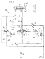
- 1 and 2 show a first and a second device for controlling a hydraulic motor, each in a simplified representation.
- FIG. 1 shows a device 10 for controlling a hydraulic motor, which is designed here as a differential cylinder 11, as is used, for example, as a locking cylinder in a plastic injection molding machine for actuating a mold.
- the differential cylinder 11 has a cylinder space 12 assigned to its large effective area and an annular space 13 assigned to the smaller effective area, the area ratio of which is 2: 1.
- the device 10 essentially has, as components, a proportional valve 14 designed as an electrohydraulic control valve, a changeover valve 15 controlled as a function of differential pressure, a pilot-operated check valve 16, and two check valves 17 and 18.
- the proportional valve 14 which is known per se, has a two-stage design, is switched into a control circuit (not shown in more detail) and, in addition to a spring-centered neutral position 19 with associated zero relief, has a first working position 21 and a second working position 22.
- An inlet connection 23 designated P is supplied with pressure medium by a pump 24 via an inlet line 25, the first check valve 17 being connected into the inlet line 25.
- a return connection designated T is connected to a tank 28 via a tank line 27, into which the check valve 16 is connected.
- a first working line 31 leads from a first motor connection 29, designated A, into the cylinder space 12 of the differential cylinder 11.
- a second motor connection 32 designated B, is connected to the annular space 13 via a second working line 33.
- the check valve 16 connected into the tank line 27 consists of a 2/2 cartridge 34, which is hydraulically piloted by a solenoid valve 35.
- the check valve 16 is designed as a normally open valve.
- a measuring throttle 36 is connected in the tank line 27 upstream from the shut-off valve 16, which is located in the tank line 27 downstream from a branch point 37.
- the pressure drop caused by the measuring throttle 36 in the tank line 27 is tapped via two control lines 38, 39 and is used for the differential pressure-dependent control of the changeover valve 15.
- the switchover valve 15 which is controlled as a function of the differential pressure, is a known throttle valve with double flow for flow force compensation. It has a spring-centered blocking position 41 in which all connections are blocked off and can be deflected into a pressure-dependent working position 42 in which the size of the pressure medium flow flowing through is controlled in proportion to the size of the pressure difference present.
- the changeover valve 15 is connected in a return line 43, which connects the cylinder space 12 of the differential cylinder 11 directly to the tank 28, this return line 43 for connecting the changeover valve 15 being partially guided in parallel sections.
- This return line 43 with its section leading to the switching valve 15 port P and the first working line 31 have a common node 44 which is connected via a bypass line 45 to the branch point 37, so that in this way the return port 26 of the proportional valve 14 bypassing Changeover valve 15, check valve 16 and measuring throttle 36 is connected directly to the cylinder chamber 12.
- this bypass line 45 the second check valve 18 is switched so that it opens towards the cylinder chamber 12.
- the operation of the device 10 is explained as follows: To close a mold in a plastic injection molding machine, the piston rod of the differential cylinder 11 is extended. For this purpose, the proportional valve 14 is adjusted electrohydraulically from its neutral position 19 into its first working position 21. At the same time, the solenoid valve 35 is excited so that the cartridge 34 blocks the tank line 24. The changeover valve 15 assumes its spring-centered blocking position 41.
- the volume flow coming from the pump 24 flows into the cylinder space 12 via the control edge PA and the first working line 31.
- the pressure medium displaced from the annular space 13 flows via the second working line 33, the control edge BT to the branch point 37 and further Via the bypass line 45 with the check valve 18 to the node 44 and further into the cylinder space 12 of the differential cylinder 11.
- an overflow circuit is realized when the piston rod is extended, the volume flow coming from the pump 24 and the volume flow taken over from the annular space 13 being different unite at node 44 and flow together into cylinder space 12.
- the piston rod in the differential cylinder 11 is retracted, for which purpose the proportional valve 14 is controlled in its second working position 22.
- the volume flow coming from the pump 24 flows via the control edge PB into the annular space 13 of the cylinder 11.
- a volume flow twice as large flows out of the cylinder space 12 through the first working line 31 due to the surface translation in the differential cylinder 11.
- This volume flow is divided into a partial flow to the switching valve 15 and another partial flow to the proportional valve 14.
- This partial flow causes a pressure difference at the measuring throttle 36, which acts on the changeover valve 15 via the control lines 38, 39 and adjusts it against spring force from the blocking position 41 into its working position 42.
- the differential pressure-controlled changeover valve 15 controls a partial flow from the node 44 via the return line 43 directly to the tank 28, the size of this volume flow being proportional to the size of the pressure difference generated by the measuring throttle 36. Due to the double flow through the changeover valve 15, flow forces in the valve are balanced; furthermore, its nominal size can be kept correspondingly small.
- the device 10 can now be designed so that at a pressure drop of approximately 5 bar at the measuring throttle 36 at maximum opening speed, half the volume flow from the cylinder space 12 in the differential cylinder 11 is controlled via the changeover valve 15 to the tank 28.
- the functions of accelerating and braking when opening the mold are still guaranteed and are determined by the proportional valve 14 using its ramp technology.
- the second check valve 18 in the bypass line 45 prevents pressure medium from flowing out of the cylinder space 12 bypassing the proportional valve 14 into the tank line 27.
- This described division of the returning, double volume flow from the cylinder chamber 12 during the closing process avoids an undesirably strong return throttling at the proportional valve 14.
- the measuring throttle 36 is arranged in the device 10 in a conduit in which volume flows can only flow back to the tank in one direction.
- the proportional valve 14 With the device 10, only a simple volume flow is always conducted via the proportional valve 14 both when the piston rod is extended and when it is retracted.
- the nominal size of this valve can accordingly be chosen to be small, which has a favorable effect, in particular on the costs, particularly in the case of large machines with large volume flows.
- the check valve 16 only needs to be designed for a simple volume flow; can therefore have a correspondingly small nominal size. It is also advantageous if, in the device 10, the measuring throttle 36 with the cartridge 34 in the check valve 16 are structurally combined in a common housing.
- the proportional valve 14 is equipped with zero relief in the neutral position 19; this prevents the lock cylinder 11 from drifting, e.g. B. when he occupies a position with an open shape.
- FIG. 2 shows a second device 50, which differs from the first device 10 as follows, the same reference numerals being used for the same components.
- the second device 50 uses a double-flow switch valve 51 with a single flow, which is designed here as a cartridge for block installation.
- the changeover valve 51 works as a proportional throttle valve and, as before, lies in the return line 43 leading to the tank 28.
- the measuring throttle 36 is connected into the first working line 31 so that it lies between the node 44 and the proportional valve 14 is coming.
- a parallel branch line 52 is provided in the first working line 31, into which a third check valve 53 opening towards the node 44 is connected. The pressure difference caused by the measuring throttle 36 is passed via the control lines 38 and 39 to the changeover valve 51.
- control line 39 is controlled by an electromagnetically adjustable pressure control valve 54 which, together with the changeover valve 51 and the throttle 56, enables a pilot-operated proportional pressure valve.
- the pressure in the annular space 13 is secured by a second pressure valve 55.
- the mode of operation of the second device 50 largely corresponds to that of the first device 10, reference being made to the following different points:
- the check valve 53 causes a significantly lower flow resistance than the measuring throttle 36, which generates a pressure drop of about 5 bar at full opening speed of the differential cylinder 11. If this pressure drop is not considered to be a nuisance in some applications, the branch line 52 with check valve 53 can also be completely omitted in the case of a measuring throttle 36 located in the working line 31.
- the pressure valve 54 is expediently designed as a proportional valve, so that different pressures can be programmed with it. In particular, the mold closing safety pressure and the closing pressure in the differential cylinder 11 and possibly other pressure functions, such as in a pressure cushion, can be regulated. An additional throttle 56 is provided in the control line 39 for these pressure functions.
- the piston rod on the differential cylinder 11 When a mold is opened, the piston rod on the differential cylinder 11 must be retracted, for which purpose the proportional valve 14 in its second working position 22 guides the volume flow coming from the pump 24 into the annular space 13, the one coming out of the cylinder space 12 flowing volume flow at node 44 is divided again.
- the measuring throttle 36 is now upstream of the proportional valve 14 in one of the partial flows and generates a pressure difference which actuates the changeover valve 51.
- the proportional valve 14 is always flowed through only with the simple volume flow, so that no excessive return throttling occurs with a relatively small nominal size.
- the throttle losses during the overflow circuit when the piston rod is extended are low and at the same time the differential cylinder 11 is well clamped.
- superimposed pressure functions can be carried out with the changeover valve 51.
- the check valve 16 is actuated by a solenoid valve 35 with a changed circuit symbol; this circuit symbol enables a better drainage of leak oil compared to FIG. 1.
- This control of the cartridge 34 used in FIG. 2 can also be used in the first device 10 according to FIG.
- valve elements can also be installed in the devices for additional functions.
- a single-stage control valve can also be used.
- a single-flow valve type can also be used in the device 10.
- the advantages of the device are also present if a rotary drive is used as the hydraulic motor.
- the present device is particularly suitable for clamping units of injection and blow molding machines.
Landscapes
- Engineering & Computer Science (AREA)
- Physics & Mathematics (AREA)
- Fluid Mechanics (AREA)
- Mechanical Engineering (AREA)
- General Engineering & Computer Science (AREA)
- Fluid-Pressure Circuits (AREA)
- Injection Moulding Of Plastics Or The Like (AREA)
Claims (9)
- Dispositif (10 ; 50) pour commander un moteur hydraulique (11), en particulier un vérin de fermeture d'une presse d'injection de matière plastique, dispositif dans le cas duquel le moteur peut être constitué sous la forme d'un vérin différentiel avec une chambre annulaire (13) et une chambre cylindrique (12) et peut être commandé au moyen d'une vanne de régulation électro-hydraulique (14), et avec un étranglement de mesure (36) qui, au moins lorsqu'on vide la chambre cylindrique (12), est branché sur un premier courant volumétrique passant par la vanne de régulation (14) et qui produit dans ce cas une différence de pression, par laquelle on peut commander une vanne d'inversion (15 ; 51) actionnée en fonction de la différence de pression et fonctionnant de façon proportionnelle, vanne qui, lorsqu'on vide la chambre cylindrique (12), commande un deuxième courant volumétrique passant parallèlement au premier courant volumétrique en direction du réservoir (28), et avec des moyens pour réaliser un circuit de trop plein et renvoyer un courant volumétrique s'écoulant de la chambre annulaire (13) dans la chambre cylindrique (12) mise dans ce cas en pression, dispositif caractérisé en ce que, dans une conduite de réservoir (27) allant du raccord de circuit de retour (26) de la vanne de régulation (14) au réservoir (28), on monte une vanne d'arrêt (16), et en ce que l'on fait passer, depuis le raccord de circuit de retour (26), une conduite de dérivation (45) qui contourne l'étranglement de mesure (36) et la vanne d'inversion (15 ; 51) et va à la chambre cylindrique (12), conduite de dérivation (45) dans laquelle est disposé un clapet anti-retour (18) qui bloque l'écoulement dans le sens allant vers le raccord (26) de circuit de retour.
- Dispositif selon la revendication 1, caractérisé en ce que l'étranglement de mesure (36) est monté dans la conduite de réservoir (27) entre la vanne de régulation (14) et la vanne d'arrêt (16).
- Dispositif selon la revendication 1 ou 2, caractérisé en ce que la vanne d'inversion est constituée sous la forme d'une vanne d'étranglement (15) à double écoulement.
- Dispositif selon la revendication 1, caractérisé en ce que l'étranglement de mesure (36) est monté dans une conduite de travail (31) allant de la vanne de régulation (14) à la chambre cylindrique (12) du vérin différentiel (11).
- Dispositif selon la revendication 4, caractérisé en ce que la conduite de travail (31) présente une conduite de dérivation (52) s'étendant en parallèle à l'étranglement de mesure (36), dans laquelle est monté un clapet anti-retour (53) qui s'ouvre en direction de la chambre cylindrique (12).
- Dispositif selon l'une des revendications 4 et 5, caractérisé en ce que l'on prévoit une vanne de pression (54) commandant la pression dans la conduite de travail (31) allant à la chambre cylindrique (12), en particulier une vanne de pression réglable (54) qui coopère avec la vanne d'inversion (51) pour avoir un fonctionnement superposé, précommandé, de pression.
- Dispositif selon l'une des revendications 4 à 6, caractérisé en ce que la vanne d'inversion (51) est réalisée sous la forme d'une cartouche à deux voies à simple écoulement.
- Dispositif selon l'une ou plusieurs des revendications 1 à 7, caractérisé en ce que la première conduite de travail (31), la conduite de dérivation (45) et la conduite de retour (43) forment, dans la zone comprise entre la vanne d'inversion (15) et la chambre cylindrique (12), un point de jonction (44).
- Dispositif selon l'une des revendications 1 à 8, caractérisé en ce que la vanne de régulation (14) présente, dans sa position neutre (19), une décharge nulle.
Applications Claiming Priority (2)
| Application Number | Priority Date | Filing Date | Title |
|---|---|---|---|
| DE4020451A DE4020451A1 (de) | 1990-06-27 | 1990-06-27 | Einrichtung zur steuerung eines hydraulischen motors |
| DE4020451 | 1990-06-27 |
Publications (2)
| Publication Number | Publication Date |
|---|---|
| EP0464481A1 EP0464481A1 (fr) | 1992-01-08 |
| EP0464481B1 true EP0464481B1 (fr) | 1995-02-01 |
Family
ID=6409182
Family Applications (1)
| Application Number | Title | Priority Date | Filing Date |
|---|---|---|---|
| EP91110125A Expired - Lifetime EP0464481B1 (fr) | 1990-06-27 | 1991-06-20 | Dispositif de commande d'un moteur hydraulique |
Country Status (3)
| Country | Link |
|---|---|
| EP (1) | EP0464481B1 (fr) |
| DE (2) | DE4020451A1 (fr) |
| ES (1) | ES2068435T3 (fr) |
Cited By (2)
| Publication number | Priority date | Publication date | Assignee | Title |
|---|---|---|---|---|
| DE102021120713A1 (de) | 2020-08-19 | 2022-03-10 | Engel Austria Gmbh | Hydraulische Antriebsvorrichtung für eine Formgebungsmaschine |
| CN115324953A (zh) * | 2022-08-09 | 2022-11-11 | 克劳斯玛菲机械(中国)有限公司 | 一种特殊注塑成型工艺中液压缸的液压系统 |
Families Citing this family (3)
| Publication number | Priority date | Publication date | Assignee | Title |
|---|---|---|---|---|
| SE500248C2 (sv) * | 1992-12-03 | 1994-05-24 | Eka Nobel Ab | Kirala adsorbenter och framställning av dessa samt föreningar på vilka adsorbenterna är baserade och framställning av dessa föreningar |
| DE19535677A1 (de) | 1995-09-26 | 1997-03-27 | Bosch Gmbh Robert | Einrichtung zur Steuerung eines hydraulischen Motors |
| CN119163655A (zh) * | 2024-10-29 | 2024-12-20 | 广东赫尔德液压科技有限公司 | 一种用于液压油杆的增压系统及其快速制动方法 |
Family Cites Families (4)
| Publication number | Priority date | Publication date | Assignee | Title |
|---|---|---|---|---|
| US3071926A (en) * | 1960-04-12 | 1963-01-08 | Hyster Co | Hydraulic lift cylinder circuit |
| US4359931A (en) * | 1981-01-19 | 1982-11-23 | The Warner & Swasey Company | Regenerative and anticavitation hydraulic system for an excavator |
| DE3219730A1 (de) * | 1982-05-26 | 1983-12-01 | Robert Bosch Gmbh, 7000 Stuttgart | Einrichtung zur steuerung eines hydraulischen servomotors |
| DE3816958C2 (de) * | 1988-05-18 | 1999-11-11 | Mannesmann Rexroth Ag | Ventilanordnung zum Absenken einer an einem hydraulichen Zylinder angreifenden Last |
-
1990
- 1990-06-27 DE DE4020451A patent/DE4020451A1/de not_active Withdrawn
-
1991
- 1991-06-20 EP EP91110125A patent/EP0464481B1/fr not_active Expired - Lifetime
- 1991-06-20 ES ES91110125T patent/ES2068435T3/es not_active Expired - Lifetime
- 1991-06-20 DE DE59104462T patent/DE59104462D1/de not_active Expired - Lifetime
Cited By (2)
| Publication number | Priority date | Publication date | Assignee | Title |
|---|---|---|---|---|
| DE102021120713A1 (de) | 2020-08-19 | 2022-03-10 | Engel Austria Gmbh | Hydraulische Antriebsvorrichtung für eine Formgebungsmaschine |
| CN115324953A (zh) * | 2022-08-09 | 2022-11-11 | 克劳斯玛菲机械(中国)有限公司 | 一种特殊注塑成型工艺中液压缸的液压系统 |
Also Published As
| Publication number | Publication date |
|---|---|
| EP0464481A1 (fr) | 1992-01-08 |
| ES2068435T3 (es) | 1995-04-16 |
| DE59104462D1 (de) | 1995-03-16 |
| DE4020451A1 (de) | 1992-01-02 |
Similar Documents
| Publication | Publication Date | Title |
|---|---|---|
| EP1092095B2 (fr) | Circuit hydraulique | |
| EP1588077B1 (fr) | Dispositif de reglage d'une transmission hydrostatique | |
| DE69021212T2 (de) | Lastdruckwiederholungsschaltung. | |
| DE2450846B2 (de) | Nebenstromventil | |
| DE10004905A1 (de) | Verfahren und Vorrichtung zur Steuerung eines Hubzylinders insbesondere von Arbeitsmaschinen | |
| DE2642337B2 (de) | Steuereinrichtung für einen doppeltwirkenden hydraulischen Motor | |
| DE69803100T2 (de) | Druckbegrenzungsmechanismus und hydraulischer Schaltkreis mit Druckbegrenzungsmechanismus | |
| DE2758234C2 (de) | Bremsventil | |
| EP1451474B1 (fr) | Dispositif d'entrainement | |
| EP0656100A1 (fr) | Dispositif de commande hydraulique. | |
| DE3340676A1 (de) | Vorrichtung zum versorgen einer steueranordnung mit steuerdruckmittel | |
| EP0111752B1 (fr) | Régulation d'un dispositif de commande pour une pompe hydrostatique à débit variable | |
| EP0464481A1 (fr) | Dispositif de commande d'un moteur hydraulique | |
| DE3505623A1 (de) | Hydraulisches wegeventil fuer eine lastdruckkompensierte steuerung | |
| EP1003972B1 (fr) | Commande a soupapes de freinage et de commande pour dispositif de rotation | |
| DE112005001711T5 (de) | Hydraulikkreis mit einem Vielfunktionswählschalter | |
| DE2218472A1 (de) | Hydrostatisches getriebe | |
| DE3222106C2 (fr) | ||
| EP0766009B1 (fr) | Système pour contrôler un moteur hydraulique | |
| DE4235698C2 (de) | Hydrostatisches Antriebssystem | |
| DE10033757B4 (de) | Steuereinrichtung für einen hydraulischen Verbraucher | |
| DE19503943C2 (de) | Bremsventilanordnung für einen reversierbaren hydraulischen Verbraucher | |
| DE19632201A1 (de) | Hydraulische Steuereinrichtung | |
| DE10011016A1 (de) | Verfahren und hydraulische Lenkeinrichtung zur Notlenkung mit einem Lenkhandrad | |
| DE4026849C2 (de) | Ventilanordnung zum Erzeugen eines Steuerdrucks in einer hydraulischen Anlage |
Legal Events
| Date | Code | Title | Description |
|---|---|---|---|
| PUAI | Public reference made under article 153(3) epc to a published international application that has entered the european phase |
Free format text: ORIGINAL CODE: 0009012 |
|
| AK | Designated contracting states |
Kind code of ref document: A1 Designated state(s): DE ES FR IT |
|
| RAP3 | Party data changed (applicant data changed or rights of an application transferred) |
Owner name: ROBERT BOSCH GMBH |
|
| 17P | Request for examination filed |
Effective date: 19920624 |
|
| 17Q | First examination report despatched |
Effective date: 19940414 |
|
| GRAA | (expected) grant |
Free format text: ORIGINAL CODE: 0009210 |
|
| AK | Designated contracting states |
Kind code of ref document: B1 Designated state(s): DE ES FR IT |
|
| ET | Fr: translation filed | ||
| REF | Corresponds to: |
Ref document number: 59104462 Country of ref document: DE Date of ref document: 19950316 |
|
| REG | Reference to a national code |
Ref country code: ES Ref legal event code: FG2A Ref document number: 2068435 Country of ref document: ES Kind code of ref document: T3 |
|
| ITF | It: translation for a ep patent filed | ||
| PLBI | Opposition filed |
Free format text: ORIGINAL CODE: 0009260 |
|
| 26 | Opposition filed |
Opponent name: MANNESMANN REXROTH GMBH Effective date: 19951014 |
|
| PLBF | Reply of patent proprietor to notice(s) of opposition |
Free format text: ORIGINAL CODE: EPIDOS OBSO |
|
| PLBF | Reply of patent proprietor to notice(s) of opposition |
Free format text: ORIGINAL CODE: EPIDOS OBSO |
|
| PLBO | Opposition rejected |
Free format text: ORIGINAL CODE: EPIDOS REJO |
|
| PLBN | Opposition rejected |
Free format text: ORIGINAL CODE: 0009273 |
|
| STAA | Information on the status of an ep patent application or granted ep patent |
Free format text: STATUS: OPPOSITION REJECTED |
|
| 27O | Opposition rejected |
Effective date: 19960615 |
|
| PGFP | Annual fee paid to national office [announced via postgrant information from national office to epo] |
Ref country code: ES Payment date: 20020626 Year of fee payment: 12 |
|
| PG25 | Lapsed in a contracting state [announced via postgrant information from national office to epo] |
Ref country code: ES Free format text: LAPSE BECAUSE OF NON-PAYMENT OF DUE FEES Effective date: 20030621 |
|
| REG | Reference to a national code |
Ref country code: ES Ref legal event code: FD2A Effective date: 20030621 |
|
| PGFP | Annual fee paid to national office [announced via postgrant information from national office to epo] |
Ref country code: FR Payment date: 20050621 Year of fee payment: 15 |
|
| REG | Reference to a national code |
Ref country code: FR Ref legal event code: ST Effective date: 20070228 |
|
| PG25 | Lapsed in a contracting state [announced via postgrant information from national office to epo] |
Ref country code: FR Free format text: LAPSE BECAUSE OF NON-PAYMENT OF DUE FEES Effective date: 20060630 |
|
| PGFP | Annual fee paid to national office [announced via postgrant information from national office to epo] |
Ref country code: IT Payment date: 20100624 Year of fee payment: 20 |
|
| PGFP | Annual fee paid to national office [announced via postgrant information from national office to epo] |
Ref country code: DE Payment date: 20100824 Year of fee payment: 20 |
|
| REG | Reference to a national code |
Ref country code: DE Ref legal event code: R071 Ref document number: 59104462 Country of ref document: DE |
|
| REG | Reference to a national code |
Ref country code: DE Ref legal event code: R071 Ref document number: 59104462 Country of ref document: DE |
|
| PG25 | Lapsed in a contracting state [announced via postgrant information from national office to epo] |
Ref country code: DE Free format text: LAPSE BECAUSE OF EXPIRATION OF PROTECTION Effective date: 20110621 |