EP0464493A2 - Divisionneur à base élevée - Google Patents
Divisionneur à base élevée Download PDFInfo
- Publication number
- EP0464493A2 EP0464493A2 EP91110168A EP91110168A EP0464493A2 EP 0464493 A2 EP0464493 A2 EP 0464493A2 EP 91110168 A EP91110168 A EP 91110168A EP 91110168 A EP91110168 A EP 91110168A EP 0464493 A2 EP0464493 A2 EP 0464493A2
- Authority
- EP
- European Patent Office
- Prior art keywords
- output
- partial
- radix
- register
- adder
- Prior art date
- Legal status (The legal status is an assumption and is not a legal conclusion. Google has not performed a legal analysis and makes no representation as to the accuracy of the status listed.)
- Granted
Links
Images

Classifications
-
- G—PHYSICS
- G06—COMPUTING OR CALCULATING; COUNTING
- G06F—ELECTRIC DIGITAL DATA PROCESSING
- G06F7/00—Methods or arrangements for processing data by operating upon the order or content of the data handled
- G06F7/38—Methods or arrangements for performing computations using exclusively denominational number representation, e.g. using binary, ternary, decimal representation
- G06F7/40—Methods or arrangements for performing computations using exclusively denominational number representation, e.g. using binary, ternary, decimal representation using contact-making devices, e.g. electromagnetic relay
- G06F7/44—Multiplying; Dividing
-
- G—PHYSICS
- G06—COMPUTING OR CALCULATING; COUNTING
- G06F—ELECTRIC DIGITAL DATA PROCESSING
- G06F7/00—Methods or arrangements for processing data by operating upon the order or content of the data handled
- G06F7/38—Methods or arrangements for performing computations using exclusively denominational number representation, e.g. using binary, ternary, decimal representation
- G06F7/48—Methods or arrangements for performing computations using exclusively denominational number representation, e.g. using binary, ternary, decimal representation using non-contact-making devices, e.g. tube, solid state device; using unspecified devices
- G06F7/52—Multiplying; Dividing
- G06F7/535—Dividing only
-
- G—PHYSICS
- G06—COMPUTING OR CALCULATING; COUNTING
- G06F—ELECTRIC DIGITAL DATA PROCESSING
- G06F7/00—Methods or arrangements for processing data by operating upon the order or content of the data handled
- G06F7/38—Methods or arrangements for performing computations using exclusively denominational number representation, e.g. using binary, ternary, decimal representation
- G06F7/48—Methods or arrangements for performing computations using exclusively denominational number representation, e.g. using binary, ternary, decimal representation using non-contact-making devices, e.g. tube, solid state device; using unspecified devices
- G06F7/49—Computations with a radix, other than binary, 8, 16 or decimal, e.g. ternary, negative or imaginary radices, mixed radix non-linear PCM
-
- G—PHYSICS
- G06—COMPUTING OR CALCULATING; COUNTING
- G06F—ELECTRIC DIGITAL DATA PROCESSING
- G06F7/00—Methods or arrangements for processing data by operating upon the order or content of the data handled
- G06F7/38—Methods or arrangements for performing computations using exclusively denominational number representation, e.g. using binary, ternary, decimal representation
- G06F7/48—Methods or arrangements for performing computations using exclusively denominational number representation, e.g. using binary, ternary, decimal representation using non-contact-making devices, e.g. tube, solid state device; using unspecified devices
- G06F7/52—Multiplying; Dividing
- G06F7/535—Dividing only
- G06F7/537—Reduction of the number of iteration steps or stages, e.g. using the Sweeny-Robertson-Tocher [SRT] algorithm
- G06F7/5375—Non restoring calculation, where each digit is either negative, zero or positive, e.g. SRT
Definitions
- This invention relates to a hardware divider used in an integrated floating processor unit (FPU), and more particularly to a high-radix divider.
- FPU integrated floating processor unit
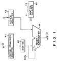
- Fig. 1 schematically shows a conventional hardware divider utilizing the nonrestoring algorithm based on the repetitive operation system.
- a partial remainder register 41 stores a dividend in the initial period of the operation and then stores a partial remainder R (j) in the remaining period.
- a partial remainder shifter 42 shifts the output of the partial remainder register 41 to the left by the radix.
- a divisor register 43 stores a divisor D.
- An adder/subtracter 44 effects the addition of or subtraction between data input from the partial remainder shifter 42 and data input from the divisor register 43 to output a partial remainder R (j+1) .
- a control counter 45 controls the operation timing of the above respective circuits.
- the conventional hardware divider utilizing the nonrestoring algorithm based on the repetitive operation system effects the division according to the following convergence equation when the radix is set to 2, the partial remainder in the preceding cycle is expressed by R (j) , the partial remainder in the current cycle is expressed by R (j+1) , the partial quotient is expressed by Q and the divisor is expressed by D.
- R (j+1) 2R (j) - QD (when j in the partial remainder R (j) is 0, a dividend is R (0) ).
- the above division system has an advantage that each time the operation for the operation loop is effected by one cycle in response to one clock, one bit of the partial quotient Q can be determined and the quotient Q can be determined based on the sign of the partial remainder 2R (j) in the preceding cycle when the partial quotient Q is ⁇ -1, 1 ⁇ .
- a mantissa portion has as many as 54 bits (a mantissa of 53 bits and a sign of 1 bit) and at least 54 clocks are necessary for effecting the division. Therefore, the latency (latent time from the instruction input to the operation output) of the operation for requiring the result of division becomes long, thereby significantly increasing the processing time. Further, in order to effectively utilize the parallel operability of the divider using the above division system, a high technique is required for the arrangement of operation instructions and it is almost impossible to use the divider to the full extent if the machine language is created by use of the compiler.
- the convergence type division algorithm based on the Newton-Raphson method may be effective at an operation speed corresponding to the latency.
- the algorithm requires two multiplications and one addition in the convergence equation and the initial value approximation, a read only memory having a certain amount of memory capacity is required.
- the investment effect of the hardware divider using the convergence type division algorithm is small and the performance thereof becomes low since the multiplication and addition/subtraction cannot be effected while the division is being effected.
- the conventional hardware divider utilizing the nonrestoring algorithm based on the repetitive operation system has a radix of 2, at least 54 clocks are necessary when the division with doubled precision is effected by the FPU. For this reason, the latency of the operation requiring the result of the division becomes long and the processing time becomes significantly long. Further, it is difficult to effectively utilize the parallel operability of the divider.
- an object of this invention is to provide a high-radix divider capable of effecting high-speed division by use of a small amount of hardware.
- a high-radix divider comprising a first register for storing a dividend or a partial remainder; a shifter for shifting an output of the first register to the left by a radix which uses the power of 2 and is larger than 2; a second register for storing a divisor; a plurality of third registers for storing comparison constants obtained by subjecting an output of the second register to predetermined operations; a plurality of magnitude comparators for respectively receiving outputs of the plurality of third registers as one input, receiving upper bits of a bit number representing a precision required for conversion and included in the outputs of the shifter as another input, and comparing the magnitudes of the two inputs with each other to derive partial quotients; a selector for shifting and selecting the output of the second register according to the signs of the partial quotients output from the plurality of magnitude comparators to create a factor having a value equal to the integer multiple of the divisor; and an adder/subtracter for receiving the outputs of the selector
- the comparison constants obtained by subjecting the divisor to the predetermined operations and the partial remainder obtained in the preceding cycle are compared (subtracted) with each other by means of the magnitude comparators (subtracters) to derive a partial quotient which permits the partial remainder obtained in the current cycle to be set within a convergence range.
- the divisor is multiplied by a constant according to the sign of the partial quotient to create a factor having a value equal to the integer multiple of the divisor and an addition of or a difference between a number derived by shifting the partial remainder in the preceding cycle to the left by the radix and the factor having the value equal to the integer multiple of the divisor is derived according to the sign bit of the shifted number so as to obtain a partial remainder in the current cycle.
- a quotient expressed by a sign r-scale notation (sign digit (SD) of the high radix) can be obtained by selecting the sign of the number derived by shifting the partial remainder in the preceding cycle to the left by the radix and the sign of the partial quotient and sequentially storing the same into the shift register.
- the divisor D is multiplied by a constant according to the sign of the partial quotient Q to create a factor having a value equal to the integer multiple of the divisor and an addition of or a difference between a number derived by shifting the partial remainder in the preceding cycle to the left by the radix and the factor having the value equal to the integer multiple of the divisor is derived according to the sign bit of the shifted number so as to obtain a partial remainder R (j+1) in the current cycle.
- a quotient expressed by a sign r-scale notation (sign digit (SD) of the high radix) can be obtained by selecting the sign of the number derived by shifting the partial remainder R (j) in the preceding cycle to the left by the radix and the sign of the partial quotient Q and sequentially storing the same into the shift register.
- the number of circuits for subjecting the divisor D to predetermined operations and the number of subtracters for comparing the outputs of the circuits with the partial remainder R (j) in the preceding cycle are respectively set to 2 and these numbers become larger as the radix becomes higher.
- a set of numbers for the partial quotient Q becomes ⁇ -2, -1, 0, 1, 2 ⁇
- a set of numbers for the partial quotient Q increases to ⁇ -4, -3, ---, 0, ---, 3, 4 ⁇ or ⁇ -8, -7, - --, 0, ---, 7, 8 ⁇
- the circuit for multiplying the divisor D by the constant according to the sign of the partial quotient Q can be obtained by a combination of a shifter and a selector.
- the circuit of a stage other than the final stage is constructed by a carry-save type adder (CSA) and the final stage circuit is constructed by a carry-look-ahead type adder (CLA) and/or a carry-select type adder to suppress the carry transfer, and it is preferable to use a 4-2 comparator (4-input adder) as an input circuit of the above adder/subtracter when the radix is set to 16.
- CSA carry-save type adder
- CLA carry-look-ahead type adder
- 4-select type adder to suppress the carry transfer
- a circuit for creating positive and negative partial quotients according to the signs of outputs of a plurality of subtracters and two shift registers for shifting and storing the positive and negative partial quotients are provided and a circuit for permitting the values stored in the two shift registers after the completion of convergence of the division is provided, and an operation is effected by use of the above adder/subtracter to obtain a quotient represented by the binary notation.
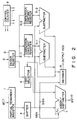
- a hardware divider (high-radix divider) based on the repetitive operation system utilizing the nonrestoring algorithm of SRT division using a radix of 4 is schematically shown.
- a first register (partial remainder register) 1 stores a dividend or a partial remainder R (j) in the preceding cycle.
- a second register (divisor register) 2 stores a divisor D.
- Third registers 3-1 and 3-2 store comparison constants obtained by subjecting the output (divisor D) from the second register to predetermined operations.
- the above operations may be different according to the radix, the precision and bit width of the divisor D, but since the constant is permitted to have a certain range when a high radix is used, the operation may generally be an extremely simple multiplication (for example, x 1, x 1.5 or x 2). Further, in order to obtain a precision which is high enough to express the above range, the bit number of the comparison constant is not necessarily set to have the same bit width of the divisor D and, for example, the comparison constant may be set to have 6 bits when a division of 54 bits is effected.
- a shifter (partial remainder shifter) 4 shifts the output of the first register 1 to the left by the radix.
- Subtracters (magnitude comparators) 5-1 and 5-2 respectively receive outputs of the third registers 3-1 and 3-2 as one input and upper bits (in this example, 6 upper bits) of a bit number representing the precision necessary for convergence and included in the outputs of the shifter 4 as the other input and compare the magnitudes of the two inputs to output a signal determining the partial quotient Q.
- a first selector 6 shifts and selects the output (divisor D) of the second register 2 according to the signs of the quotients Q output from the subtracters 5-1 and 5-2 to create a factor having a value which is an integer multiple of the divisor D.
- An adder/subtracter 7 is supplied with an output of the first selector 6 and an output of the shifter (partial remainder shifter) 4.
- the addition or subtraction of the adder/subtracter 7 is selectively specified by a sign bit of the output of the shifter 4 so as to derive a partial remainder R (j+1) in the present cycle.
- a decoder 8 is supplied with a signal for determining the partial quotient Q and a sign bit of the output from the shifter 4 to output a high-radix sign digit SD.
- a control counter 9 controls the operation timing of the above circuits.
- the division is effected based on the above-described principle and two bits of a partial quotient Q are determined each time one cycle of the operation loop is effected by one clock. Therefore, a high-speed division whose operation speed is twice (which is generally represented by log2r) as high as that of the conventional hardware divider utilizing the nonrestoring algorithm based on the repetitive operation system having a radix of 2 can be effected.
- the comparison (subtraction) between the comparison constants obtained by subjecting a divisor to predetermined operations and the partial remainder in the preceding cycle is not necessarily effected for all of the bits, and if an error is limited within the redundancy range of the partial remainder, the error can be compensated for in the next operation cycle. More specifically, when a 54-bit division is effected, it is sufficient if, for example, 6 bits of the shifted partial remainder are selected as a bit number representing the precision necessary for convergence and subjected to the comparison (subtraction), and therefore an amount of hardware can be reduced.
- Fig. 3 schematically shows another example of the construction of a high-radix divider based on the repetitive operation system utilizing the algorithm of SRT division having a radix of 4.
- the high-radix divider is constructed so as to output a quotient represented by a normal binary notation.
- a positive sign shift register 21, negative sign shift register 22, decoder 23 (substantially the same as the decoder 8) and second selectors 24-1 and 24-2 are provided in addition to the divider having the radix of 4 shown in Fig. 2.
- the decoder 23 selects positive and negative partial quotients according to the sign of the outputs of the subtracters 5-1 and 5-2.
- the two shift registers 21 and 22 shift and store the positive and negative partial quotients selected by the decoder 23.
- the selectors 24-1 and 24-2 are controlled to permit the values stored in the two shift registers 21 and 22 to be input to the adder/subtracter 7 after the completion of convergence of the division. Then, the values are operated by the adder/subtracter 7 so as to be converted into a binary notation.
- the other basic operations are the same as those of the circuit shown in Fig. 2.
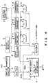
- Fig. 4 schematically shows a high-radix divider based on the repetitive operation system utilizing the algorithm of SRT division having a radix of 16.
- the high-radix divider is different from the divider having a radix of 2 and shown in Fig. 2 in that a different number of third registers (comparison constant registers) 3 and subtracters 5 are used, the first selector 6' of different construction is used and a 4-input adder 10 is used in the input circuit of the adder/subtracter 7, and is substantially the same as the latter in other respects.
- a high-radix divider capable of effecting a division at a high speed by use of a small amount of hardware can be provided.
Landscapes
- Engineering & Computer Science (AREA)
- Physics & Mathematics (AREA)
- General Physics & Mathematics (AREA)
- Theoretical Computer Science (AREA)
- Mathematical Optimization (AREA)
- Pure & Applied Mathematics (AREA)
- Mathematical Analysis (AREA)
- Computational Mathematics (AREA)
- Computing Systems (AREA)
- General Engineering & Computer Science (AREA)
- Nonlinear Science (AREA)
- Electromagnetism (AREA)
- Complex Calculations (AREA)
Applications Claiming Priority (2)
| Application Number | Priority Date | Filing Date | Title |
|---|---|---|---|
| JP166202/90 | 1990-06-25 | ||
| JP2166202A JP2835153B2 (ja) | 1990-06-25 | 1990-06-25 | 高基数除算器 |
Publications (3)
| Publication Number | Publication Date |
|---|---|
| EP0464493A2 true EP0464493A2 (fr) | 1992-01-08 |
| EP0464493A3 EP0464493A3 (en) | 1993-08-18 |
| EP0464493B1 EP0464493B1 (fr) | 1998-12-16 |
Family
ID=15826988
Family Applications (1)
| Application Number | Title | Priority Date | Filing Date |
|---|---|---|---|
| EP91110168A Expired - Lifetime EP0464493B1 (fr) | 1990-06-25 | 1991-06-20 | Divisionneur à base élevée |
Country Status (5)
| Country | Link |
|---|---|
| US (1) | US5105378A (fr) |
| EP (1) | EP0464493B1 (fr) |
| JP (1) | JP2835153B2 (fr) |
| KR (1) | KR940008615B1 (fr) |
| DE (1) | DE69130623T2 (fr) |
Families Citing this family (23)
| Publication number | Priority date | Publication date | Assignee | Title |
|---|---|---|---|---|
| US5193036A (en) * | 1990-10-02 | 1993-03-09 | International Business Machines Corporation | Transducer head skew arrangement for disk drive system |
| JPH04172526A (ja) * | 1990-11-07 | 1992-06-19 | Toshiba Corp | 浮動小数点除算器 |
| JPH0731592B2 (ja) * | 1990-11-29 | 1995-04-10 | 株式会社東芝 | 除算回路 |
| US6173305B1 (en) | 1993-11-30 | 2001-01-09 | Texas Instruments Incorporated | Division by iteration employing subtraction and conditional source selection of a prior difference or a left shifted remainder |
| US5442581A (en) * | 1993-11-30 | 1995-08-15 | Texas Instruments Incorporated | Iterative division apparatus, system and method forming plural quotient bits per iteration |
| US5644524A (en) * | 1993-11-30 | 1997-07-01 | Texas Instruments Incorporated | Iterative division apparatus, system and method employing left most one's detection and left most one's detection with exclusive or |
| DE69529047D1 (de) * | 1994-10-05 | 2003-01-16 | Ibm | Festkomma-Dividiervorrichtung ohne Rückstellung |
| FR2728702A1 (fr) * | 1994-12-22 | 1996-06-28 | France Telecom | Composant electronique capable notamment d'effectuer une division de deux nombres en base 4 |
| US5696712A (en) * | 1995-07-05 | 1997-12-09 | Sun Microsystems, Inc. | Three overlapped stages of radix-2 square root/division with speculative execution |
| US6360241B1 (en) * | 1999-02-01 | 2002-03-19 | Compaq Information Technologies Goup, L.P. | Computer method and apparatus for division and square root operations using signed digit |
| US6732135B1 (en) | 1999-02-01 | 2004-05-04 | Hewlett-Packard Development Company, L.P. | Method and apparatus for accumulating partial quotients in a digital processor |
| US6604121B1 (en) | 1999-05-07 | 2003-08-05 | Seagate Technology Llc | Digital division device and method using a reduced-sized lookup table |
| JP4042364B2 (ja) * | 2001-07-27 | 2008-02-06 | 日本電気株式会社 | アドレス生成回路、選択判断回路 |
| US7539720B2 (en) * | 2004-12-15 | 2009-05-26 | Sun Microsystems, Inc. | Low latency integer divider and integration with floating point divider and method |
| US7607068B2 (en) | 2006-08-31 | 2009-10-20 | Intel Corporation | Apparatus and method for generating a Galois-field syndrome |
| US7738657B2 (en) * | 2006-08-31 | 2010-06-15 | Intel Corporation | System and method for multi-precision division |
| US7797612B2 (en) * | 2006-12-29 | 2010-09-14 | Intel Corporation | Storage accelerator |
| US7830905B2 (en) * | 2007-04-20 | 2010-11-09 | Cray Inc. | Speculative forwarding in a high-radix router |
| US8898215B2 (en) | 2007-06-28 | 2014-11-25 | King Fahd University Of Petroleum And Minerals | High-radix multiplier-divider |
| US20090006509A1 (en) * | 2007-06-28 | 2009-01-01 | Alaaeldin Amin | High-radix multiplier-divider |
| US8452831B2 (en) * | 2009-03-31 | 2013-05-28 | Oracle America, Inc. | Apparatus and method for implementing hardware support for denormalized operands for floating-point divide operations |
| JP4858794B2 (ja) * | 2009-12-02 | 2012-01-18 | 日本電気株式会社 | 浮動小数点除算器、及びそれを用いた情報処理装置 |
| US9086890B2 (en) | 2012-01-06 | 2015-07-21 | Oracle International Corporation | Division unit with normalization circuit and plural divide engines for receiving instructions when divide engine availability is indicated |
Family Cites Families (9)
| Publication number | Priority date | Publication date | Assignee | Title |
|---|---|---|---|---|
| US3684879A (en) * | 1970-09-09 | 1972-08-15 | Sperry Rand Corp | Division utilizing multiples of the divisor stored in an addressable memory |
| CA1231455A (fr) * | 1984-04-09 | 1988-01-12 | Masayuki Ikeda | Diviseur non retablisseur |
| JPS61166628A (ja) * | 1985-01-18 | 1986-07-28 | Hitachi Ltd | 除算装置 |
| JP2508784B2 (ja) * | 1988-02-17 | 1996-06-19 | 日本電気株式会社 | 指数関数演算装置 |
| US5023827A (en) * | 1988-08-18 | 1991-06-11 | Digital Equipment Corporation | Radix-16 divider using overlapped quotient bit selection and concurrent quotient rounding and correction |
| JPH0264730A (ja) * | 1988-08-31 | 1990-03-05 | Nec Corp | 演算装置 |
| JPH02190928A (ja) * | 1989-01-19 | 1990-07-26 | Nec Corp | 除算器 |
| US4996660A (en) * | 1989-04-17 | 1991-02-26 | International Business Machines Corporation | Selection of divisor multipliers in a floating point divide circuit |
| US4979142A (en) * | 1989-04-17 | 1990-12-18 | International Business Machines Corporation | Two-bit floating point divide circuit with single carry-save adder |
-
1990
- 1990-06-25 JP JP2166202A patent/JP2835153B2/ja not_active Expired - Fee Related
-
1991
- 1991-06-18 US US07/717,045 patent/US5105378A/en not_active Expired - Lifetime
- 1991-06-20 EP EP91110168A patent/EP0464493B1/fr not_active Expired - Lifetime
- 1991-06-20 DE DE69130623T patent/DE69130623T2/de not_active Expired - Fee Related
- 1991-06-21 KR KR1019910010265A patent/KR940008615B1/ko not_active Expired - Fee Related
Also Published As
| Publication number | Publication date |
|---|---|
| JP2835153B2 (ja) | 1998-12-14 |
| US5105378A (en) | 1992-04-14 |
| KR920001328A (ko) | 1992-01-30 |
| KR940008615B1 (ko) | 1994-09-24 |
| EP0464493B1 (fr) | 1998-12-16 |
| DE69130623D1 (de) | 1999-01-28 |
| DE69130623T2 (de) | 1999-06-02 |
| EP0464493A3 (en) | 1993-08-18 |
| JPH0454633A (ja) | 1992-02-21 |
Similar Documents
| Publication | Publication Date | Title |
|---|---|---|
| EP0464493B1 (fr) | Divisionneur à base élevée | |
| US4939686A (en) | Method and apparatus for shared radix 4 division and radix 4 square root | |
| EP0149248B1 (fr) | Méthode et dispositif à division utilisant une approximation à interpolation | |
| EP0450754B1 (fr) | Divisionneurs à grande vitesse | |
| US6230179B1 (en) | Finite field multiplier with intrinsic modular reduction | |
| JP3689183B2 (ja) | 正確な浮動小数点除算/平方根演算を実現する正確、かつ効果的なスティッキー・ビット計算 | |
| EP0450804A2 (fr) | Unité du type "pipelined" pour le traitement de nombres représentés en virgule flottante | |
| CA1142650A (fr) | Diviseur binaire avec addionneurs a report | |
| EP0136834A2 (fr) | Circuit numérique exécutant une opération arithmétique avec débordement | |
| US6108682A (en) | Division and/or square root calculating circuit | |
| EP0717350A2 (fr) | Unité de calcul pour division et racine carrée à grande vitesse | |
| KR100203468B1 (ko) | 부동소수점수를 위한 산술연산장치 | |
| US5784307A (en) | Division algorithm for floating point or integer numbers | |
| US4594680A (en) | Apparatus for performing quadratic convergence division in a large data processing system | |
| US5357455A (en) | Floating point remainder generator for a math processor | |
| US5790444A (en) | Fast alignment unit for multiply-add floating point unit | |
| US5954790A (en) | Method and apparatus for parallel prediction and computation of massive cancellation in floating point subtraction | |
| US4899302A (en) | Arithmetic unit for inverse trigonometric function | |
| US5818745A (en) | Computer for performing non-restoring division | |
| US5910910A (en) | Circuit and method for rapid calculation of quotients and square roots | |
| US7127483B2 (en) | Method and system of a microprocessor subtraction-division floating point divider | |
| US7243119B1 (en) | Floating point computing unit | |
| JP3252954B2 (ja) | 乗算方法および乗算回路 | |
| US5208769A (en) | Unsigned integer multiply/divide circuit | |
| JPH0578049B2 (fr) |
Legal Events
| Date | Code | Title | Description |
|---|---|---|---|
| PUAI | Public reference made under article 153(3) epc to a published international application that has entered the european phase |
Free format text: ORIGINAL CODE: 0009012 |
|
| 17P | Request for examination filed |
Effective date: 19910620 |
|
| AK | Designated contracting states |
Kind code of ref document: A2 Designated state(s): DE FR GB |
|
| PUAL | Search report despatched |
Free format text: ORIGINAL CODE: 0009013 |
|
| AK | Designated contracting states |
Kind code of ref document: A3 Designated state(s): DE FR GB |
|
| 17Q | First examination report despatched |
Effective date: 19970210 |
|
| GRAG | Despatch of communication of intention to grant |
Free format text: ORIGINAL CODE: EPIDOS AGRA |
|
| GRAG | Despatch of communication of intention to grant |
Free format text: ORIGINAL CODE: EPIDOS AGRA |
|
| GRAH | Despatch of communication of intention to grant a patent |
Free format text: ORIGINAL CODE: EPIDOS IGRA |
|
| GRAH | Despatch of communication of intention to grant a patent |
Free format text: ORIGINAL CODE: EPIDOS IGRA |
|
| GRAA | (expected) grant |
Free format text: ORIGINAL CODE: 0009210 |
|
| RBV | Designated contracting states (corrected) |
Designated state(s): DE |
|
| AK | Designated contracting states |
Kind code of ref document: B1 Designated state(s): DE |
|
| REF | Corresponds to: |
Ref document number: 69130623 Country of ref document: DE Date of ref document: 19990128 |
|
| PLBE | No opposition filed within time limit |
Free format text: ORIGINAL CODE: 0009261 |
|
| STAA | Information on the status of an ep patent application or granted ep patent |
Free format text: STATUS: NO OPPOSITION FILED WITHIN TIME LIMIT |
|
| 26N | No opposition filed | ||
| PGFP | Annual fee paid to national office [announced via postgrant information from national office to epo] |
Ref country code: DE Payment date: 20060615 Year of fee payment: 16 |
|
| PG25 | Lapsed in a contracting state [announced via postgrant information from national office to epo] |
Ref country code: DE Free format text: LAPSE BECAUSE OF NON-PAYMENT OF DUE FEES Effective date: 20080101 |