EP0464495A1 - Verfahren und Vorrichtung zur Messung der Absorption von lichtstreuenden Stoffen - Google Patents
Verfahren und Vorrichtung zur Messung der Absorption von lichtstreuenden Stoffen Download PDFInfo
- Publication number
- EP0464495A1 EP0464495A1 EP91110178A EP91110178A EP0464495A1 EP 0464495 A1 EP0464495 A1 EP 0464495A1 EP 91110178 A EP91110178 A EP 91110178A EP 91110178 A EP91110178 A EP 91110178A EP 0464495 A1 EP0464495 A1 EP 0464495A1
- Authority
- EP
- European Patent Office
- Prior art keywords
- scattering material
- light scattering
- laser
- laser light
- intensity
- Prior art date
- Legal status (The legal status is an assumption and is not a legal conclusion. Google has not performed a legal analysis and makes no representation as to the accuracy of the status listed.)
- Granted
Links
- 238000000149 argon plasma sintering Methods 0.000 title claims abstract description 79
- 239000000463 material Substances 0.000 title claims abstract description 65
- 238000000034 method Methods 0.000 title claims abstract description 15
- 230000031700 light absorption Effects 0.000 title abstract description 37
- 238000005259 measurement Methods 0.000 claims description 12
- 239000004065 semiconductor Substances 0.000 claims description 8
- 230000010355 oscillation Effects 0.000 claims description 3
- 230000001678 irradiating effect Effects 0.000 claims 4
- 238000007519 figuring Methods 0.000 claims 2
- 239000000126 substance Substances 0.000 abstract description 10
- 230000009102 absorption Effects 0.000 description 30
- 238000010521 absorption reaction Methods 0.000 description 30
- 239000000523 sample Substances 0.000 description 27
- 102000001554 Hemoglobins Human genes 0.000 description 20
- 108010054147 Hemoglobins Proteins 0.000 description 20
- 238000010276 construction Methods 0.000 description 11
- 238000009499 grossing Methods 0.000 description 8
- 230000003287 optical effect Effects 0.000 description 8
- 238000006213 oxygenation reaction Methods 0.000 description 5
- 210000004369 blood Anatomy 0.000 description 4
- 239000008280 blood Substances 0.000 description 4
- 238000009795 derivation Methods 0.000 description 4
- 230000004913 activation Effects 0.000 description 3
- 238000010586 diagram Methods 0.000 description 3
- 210000003743 erythrocyte Anatomy 0.000 description 3
- 239000012780 transparent material Substances 0.000 description 3
- 238000000862 absorption spectrum Methods 0.000 description 2
- 230000002238 attenuated effect Effects 0.000 description 2
- 230000005540 biological transmission Effects 0.000 description 2
- 238000006392 deoxygenation reaction Methods 0.000 description 2
- 239000000284 extract Substances 0.000 description 2
- 239000002245 particle Substances 0.000 description 2
- 238000001228 spectrum Methods 0.000 description 2
- 239000011358 absorbing material Substances 0.000 description 1
- 210000000601 blood cell Anatomy 0.000 description 1
- 239000013078 crystal Substances 0.000 description 1
- 230000000694 effects Effects 0.000 description 1
- 238000004519 manufacturing process Methods 0.000 description 1
- 239000000203 mixture Substances 0.000 description 1
- 238000002798 spectrophotometry method Methods 0.000 description 1
Images


Classifications
-
- G—PHYSICS
- G01—MEASURING; TESTING
- G01N—INVESTIGATING OR ANALYSING MATERIALS BY DETERMINING THEIR CHEMICAL OR PHYSICAL PROPERTIES
- G01N21/00—Investigating or analysing materials by the use of optical means, i.e. using sub-millimetre waves, infrared, visible or ultraviolet light
- G01N21/17—Systems in which incident light is modified in accordance with the properties of the material investigated
- G01N21/25—Colour; Spectral properties, i.e. comparison of effect of material on the light at two or more different wavelengths or wavelength bands
- G01N21/31—Investigating relative effect of material at wavelengths characteristic of specific elements or molecules, e.g. atomic absorption spectrometry
- G01N21/39—Investigating relative effect of material at wavelengths characteristic of specific elements or molecules, e.g. atomic absorption spectrometry using tunable lasers
-
- G—PHYSICS
- G01—MEASURING; TESTING
- G01N—INVESTIGATING OR ANALYSING MATERIALS BY DETERMINING THEIR CHEMICAL OR PHYSICAL PROPERTIES
- G01N21/00—Investigating or analysing materials by the use of optical means, i.e. using sub-millimetre waves, infrared, visible or ultraviolet light
- G01N21/17—Systems in which incident light is modified in accordance with the properties of the material investigated
- G01N21/47—Scattering, i.e. diffuse reflection
- G01N21/49—Scattering, i.e. diffuse reflection within a body or fluid
- G01N21/53—Scattering, i.e. diffuse reflection within a body or fluid within a flowing fluid, e.g. smoke
- G01N21/534—Scattering, i.e. diffuse reflection within a body or fluid within a flowing fluid, e.g. smoke by measuring transmission alone, i.e. determining opacity
-
- G—PHYSICS
- G01—MEASURING; TESTING
- G01N—INVESTIGATING OR ANALYSING MATERIALS BY DETERMINING THEIR CHEMICAL OR PHYSICAL PROPERTIES
- G01N21/00—Investigating or analysing materials by the use of optical means, i.e. using sub-millimetre waves, infrared, visible or ultraviolet light
- G01N21/17—Systems in which incident light is modified in accordance with the properties of the material investigated
- G01N21/25—Colour; Spectral properties, i.e. comparison of effect of material on the light at two or more different wavelengths or wavelength bands
- G01N21/31—Investigating relative effect of material at wavelengths characteristic of specific elements or molecules, e.g. atomic absorption spectrometry
- G01N21/314—Investigating relative effect of material at wavelengths characteristic of specific elements or molecules, e.g. atomic absorption spectrometry with comparison of measurements at specific and non-specific wavelengths
- G01N2021/3148—Investigating relative effect of material at wavelengths characteristic of specific elements or molecules, e.g. atomic absorption spectrometry with comparison of measurements at specific and non-specific wavelengths using three or more wavelengths
-
- G—PHYSICS
- G01—MEASURING; TESTING
- G01N—INVESTIGATING OR ANALYSING MATERIALS BY DETERMINING THEIR CHEMICAL OR PHYSICAL PROPERTIES
- G01N21/00—Investigating or analysing materials by the use of optical means, i.e. using sub-millimetre waves, infrared, visible or ultraviolet light
- G01N21/17—Systems in which incident light is modified in accordance with the properties of the material investigated
- G01N21/25—Colour; Spectral properties, i.e. comparison of effect of material on the light at two or more different wavelengths or wavelength bands
- G01N21/31—Investigating relative effect of material at wavelengths characteristic of specific elements or molecules, e.g. atomic absorption spectrometry
- G01N21/314—Investigating relative effect of material at wavelengths characteristic of specific elements or molecules, e.g. atomic absorption spectrometry with comparison of measurements at specific and non-specific wavelengths
- G01N2021/3181—Investigating relative effect of material at wavelengths characteristic of specific elements or molecules, e.g. atomic absorption spectrometry with comparison of measurements at specific and non-specific wavelengths using LEDs
-
- G—PHYSICS
- G01—MEASURING; TESTING
- G01N—INVESTIGATING OR ANALYSING MATERIALS BY DETERMINING THEIR CHEMICAL OR PHYSICAL PROPERTIES
- G01N21/00—Investigating or analysing materials by the use of optical means, i.e. using sub-millimetre waves, infrared, visible or ultraviolet light
- G01N21/17—Systems in which incident light is modified in accordance with the properties of the material investigated
- G01N21/25—Colour; Spectral properties, i.e. comparison of effect of material on the light at two or more different wavelengths or wavelength bands
- G01N21/31—Investigating relative effect of material at wavelengths characteristic of specific elements or molecules, e.g. atomic absorption spectrometry
- G01N21/39—Investigating relative effect of material at wavelengths characteristic of specific elements or molecules, e.g. atomic absorption spectrometry using tunable lasers
- G01N2021/396—Type of laser source
- G01N2021/399—Diode laser
Definitions
- the present invention relates to a method and an equipment for measuring a coefficient of light absorption of substances contained in light scattering materials.
- I0 represents the intensity of incident light injected in the transparent material
- ⁇ the coefficient of absorption representing the rate of decrease of light due to light absorption per unit thickness of the material
- d the thickness of the material (optical path length). Consequently such a coefficient of light absorption ⁇ of the transparent material can be obtained, starting from a value obtained by measuring the intensity of light, which has been transmitted through the material, using Eq. (1).
- the present invention has been done in order to remove such a drawback by the prior art method and the object thereof is to provide an improved measuring method capable of measuring a light absorption coefficient of various sorts of substances contained in light scattering materials and a measuring equipment for realizing the method.
- the wavelength of light transmitted by the light scattering materials is varied and the coefficient of light absorption is calculated, starting from the rate of the variation in the intensity of transmitted light with respect to the variation in the wavelength.
- a light scattering material is irradiated alternately with a first and a second laser light beam having slightly different wavelength within a wavelength region selectively absorbed by the light scattering material; a first ratio of a ratio of an intensity difference between the first and the second laser light beam transmitted through the light scattering material to a wavelength difference between the first and the second laser light beam to the intensity of the first laser light beam transmitted through the light scattering material is measured; the light scattering material is irradiated alternately with a third and a fourth laser light beam having slightly different wavelengths outside of the wavelength region selectively absorbed by the light scattering material; a second ratio of a ratio of an intensity difference between the third and the fourth laser light beam transmitted through the light scattering material to a wavelength difference between the third and the fourth laser light beam to the intensity of the third laser light beam transmitted through the light scattering material is measured; and a difference between the first ratio and the second ratio is figured out to
- Attenuation of light due to light scattering which acts as measurement noise, when the coefficient of absorption is obtained by measuring the intensity of transmitted light, is produced by reflection, diffraction, refraction, etc. of light used for the measurement.
- a light scattering material there exist interfaces due to variations in the composition and particles, which are factors of light scattering.
- the intensity of the light scattering varies, depending on the magnitude of variations in the refraction index at the interfaces described above, direction of the interfaces shape of the interfaces, size, shape and direction of the particles described above, intensity of light absorption, etc. Further these factors of light scattering have different wavelength dependences. In the case where, taking a certain wavelength as a reference, the wavelength is varied in the neighborhood thereof, there are factors of scattering acting so as to increase the amount of transmitted light and on the contrary there exist also factors of scattering acting so as to decrease it.
- characteristics of light absorption by a light absorbing substance have a shape proper to that substance. This shape proper to that substance remains unchanged, even if the substance is in a light scattering material.
- the rate of decrease in the intensity of transmitted light due to the absorption by an optical absorbing material when the wavelength of light is varied, is proportional to the value of tangent of an absorption spectrum curve. Consequently, in a wavelength region of the absorption spectrum curve, where there is a light absorption peak, the rate of variations in the rate of decrease in the intensity of transmitted light due to light absorption is very great.
- the rates of variations in the rate of decrease in the intensity of transmitted light with respect to variations in the wavelength differ remarkably from each other in the magnitude thereof for the attenuation due to light scattering and for the attenuation due to light absorption.
- light absorption characteristics of a light absorbing substance contained in a light scattering material are measured with a high precision, utilizing this difference.
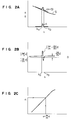
- Fig. 1 shows a fundamental construction of the equipment for measuring absorptance of light scattering materials according to the present invention.
- This equipment consists roughly of a light source unit, optical measurement units and a signal processing unit.
- reference numerals 11 to 17 as well as 19 to 35 denote elements constituting the light source unit and 36 to 51 denote elements constituting the optical measurement units and the signal processing unit.
- 18 represents a sample to be measured.
- the light source unit described above is provided with 4 semiconductor laser devices (hereinbelow called laser diodes) 13, 21, 26 and 32, which are activated by separate diode power supplies 12, 20, 25 and 31, respectively.
- Further clock signal generating circuits 11 and 24 are disposed for controlling these laser diode power supplies to determine duty cycle of laser light pulses of the different laser diodes.
- clock signal inverting circuits 19 and 30 on the input sides of clock signals to the power supplies 20 and 31, respectively, so that clock signals coming from the clock signal generating circuits 11 and 24 are transmitted to the laser diode power supplies 20 and 31, after having been inverted by the inverting circuits 19 and 30, respectively. Since oscillations of the laser diodes 21 and 32 are controlled by these inverted signals, the laser diodes 21 and 32 are oscillated (activated) alternately with respect to the laser diodes 13 and 26, respectively.
- the wavelength of laser of the laser diode 21 is selected at a wavelength ⁇ 1 + ⁇ 1, which is slightly different from the wavelength of laser ⁇ 1 of the laser diode 13, while the wavelength of laser of the laser diode 32 is selected at a wavelength ⁇ 2 + ⁇ 2, which is slightly different from the wavelength of laser ⁇ 2 of the laser diode 26.
- the laser light beams 15, 23, 28 and 34 outputted by these laser diodes 13, 21, 26 and 32 are guided to one optical path 35 through optical elements such as polarizer 16, 29, a dichroic mirror 17, etc. after having been transformed into parallel beams by means of collimator lenses 14, 22, 27 and 33, respectively, so that the sample is irradiated therewith.
- Eq. (3) expresses that by differentiating the intensity of transmitted light I t with respect to the wavelength ⁇ and multiplying the derivative.
- a value is obtained, which is proportional (proportionality coefficient being d) to the sum of the derivative by wavelength of the absorption coefficient ⁇ and the derivative by wavelength of the scattering coefficient s.
- Figs. 2A and 2B are graphs indicating the wavelength dependences of the absorption coefficient ⁇ as well as the scattering coefficient s and the derivative by wavelength, respectively.
- the curve ( ⁇ ) in Fig. 2A represents the absorption coefficient ⁇ of the sample material and the curve (s) similarly the scattering coefficient s of the sample material. Consequently the intensity spectrum of the light transmitted by the sample material can be expressed by a curve ( ⁇ + s), for which influences of both the coefficient of absorption ⁇ and the coefficient of scattering s are taken into account.
- the coefficient of absorption ⁇ increases in a wavelength region between ⁇ a and ⁇ b .
- real values of ⁇ a and ⁇ b and the height at the peak of the coefficient of absorption ⁇ between these wavelengths are different for every sample material.
- the number of wavelength regions, where the coefficient of absorption ⁇ increases is not necessarily restricted to 1, but there may be a plurality of such regions, depending on the sample material.
- the coefficient of scattering s is a relatively great value, variations in the coefficient with respect to variations in the wavelength are relatively small so that the curve (s) in the whole varies only slowly.
- Fig. 2B shows a curve representing the derivative by wavelength of the curve ( ⁇ + s) indicated in Fig. 2A.
- the value varies significantly in the wavelength region between ⁇ a and ⁇ b .
- This variation is principally due to the variation in the derivative of the curve ( ⁇ ) indicated in Fig. 2A.
- Fig. 2C shows a curve representing the relation between the coefficient of absorption ⁇ and the derivation by wavelength thereof.
- the light beam 36 transmitted by the sample 18 is collected by a condenser lens 37 and light 38 thus collected is separated by a dichroic mirror 39 with respect to the wavelength. Light beams thus separated with respect to the wavelength are injected in photodetectors 40 and 46, respectively.
- the dichroic mirror 39 is a reflecting mirror for separating the incident beam with respect to the wavelength into a transmitted light beam in the wavelength region between ⁇ 1 and ⁇ 1 + ⁇ 1 and a transmitted light beam in the wavelength region between ⁇ 2 + ⁇ 2.
- the transmitted light beam in the wavelength region between ⁇ 1 and ⁇ 1 + ⁇ 1 is injected in the photodetector 40. Since the laser diodes 13 and 21 are repeatedly alternately activated with a period ⁇ 1 of the clock signal coming from the clock signal generating circuit 11, the transmitted light beam of wavelength ⁇ 1 and the transmitted light beam of wavelength ⁇ 1 + ⁇ 1 are injected alternately in the photodetector 40. In the case where the coefficients of transmission in the sample 18 are equal to each other for the wavelength ⁇ 1 and the wavelength ⁇ 1 + ⁇ 1, since the transmitted light intensities are equal to each other for the wavelength ⁇ 1 and the wavelength ⁇ 1 + ⁇ 1, the output of the photodetector 40 has only a DC component.
- the output of the photodetector 40 includes an AC component of period ⁇ 1.
- the magnitude of the amplitude of this AC component is proportional to a difference ⁇ I ⁇ 1 between the transmitted light intensities for the wavelength ⁇ 1 and the wavelength ⁇ 1 + ⁇ 1.
- Filter circuits 41 and 44 are connected with the photodetector 40 on the output side. The former 41 makes the AC component of period ⁇ 1 pass through and the latter 44 makes the DC component pass through.
- a smoothing circuit 42 for smoothing the AC component, which has been made selectively pass through.
- a calculating circuit 43 disposed further thereafter is used for calculating the value of S1, which is expressed by a following formula, using the output of the smoothing circuit 42 and the output of the filter circuit 44; where C is a coefficient determined by characteristics of the equipment.
- the transmitted light beam of wavelength ⁇ 2 and the transmitted light beam of of wavelength ⁇ 2 + ⁇ 2 are injected in the photodetector 46.
- filter circuits 47 and 50 as well as a smoothing circuit 48 are disposed on the output side of the photodetector 46. Further the value of S2, which is expressed by a following formula, is calculated by means of a calculating circuit 49:
- the present embodiment relates to a method and an equipment for measuring the light absorption by hemoglobin in blood. Since the hemoglobin in blood is contained in the red blood cells, when they are irradiated with light, it is reflected at the surface of the blood cells to give rise to scattered light. Since this scattered light acts as significant noise light, heretofore it was not possible to measure directly light absorbing characteristics of hemoglobin existing within the red blood cells. Usually red blood cells were destroyed so that hemoglobin contained therein was eluted and thereafter measurement of the coefficient of light absorption was effected, using this eluted hemoglobin.
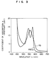
- Fig. 3 indicates an aspect of variations in light absorption characteristics, when hemoglobin in blood is oxygenated and when it is deoxygenated.
- the curve designated by HbO2 indicates the light absorption characteristics when the hemoglobin is oxygenated and the curve designated by Hb indicates them when the hemoglobin is deoxygenated.
- Concerning these characteristics there is a report by Van Aassendelft, entitled “Spectrophotometry of Hemoglobin Derivatives" (C.C. Thomas, Springfield, IL 1970).
- Van Aassendelft entitled “Spectrophotometry of Hemoglobin Derivatives" (C.C. Thomas, Springfield, IL 1970).
- Van Aassendelft entitled “Spectrophotometry of Hemoglobin Derivatives” (C.C. Thomas, Springfield, IL 1970).
- a curve representing the coefficient of absorption has double peaks, when hemoglobin is perfectly oxygenated, while it has a single peak, when hemoglobin is perfectly deoxygenated.
- Fig. 4 indicates the construction of the equipment used in the present embodiment.
- the construction of this equipment is basically the construction of the equipment indicated in Fig. 1, to which attenuation filters 61 and 62 are added.
- elements having wavelengths of laser of 570 nm, 572 nm, 670 nm and 672 nm are used for the laser diodes 14, 21, 26 and 32, respectively.
- elements having same laser characteristics are used for every group.
- the diference of 2 nm between the wavelengths of the two elements is produced by varying the laser power for the two elements. This utilizes the phenomenon that even for elements having completely identical laser characteristics, when laser powers thereof are different, since heat productions at the junction portions thereof are different, temperatures at the junction portions are also different and that therefore, since energy band gaps of semiconductor crystals therefor are different, the wavelengths of laser are different.
- the attenuation filters newly added in the present embodiment are disposed for equalizing powers of the laser light beams 23 and 34 outputted by the laser diodes 21 and 32 to powers of the laser light beams 15 and 28 outputted by the laser diodes 13 and 26, respectively.
- the frequencies of the clock signals outputted by the clock signal generating circuits 11 and 24 for controlling the duty cycles of laser light pulses of the laser diodes are 1 MHz and 1.5 MHz, respectively.
- the dichroic mirrors 17 and 39 are mirrors using thin multilayers for reflection layers, provided with characteristics, by which light beams of wavelengths of 570 nm and 572 nm are made pass through and light beams of wavelengths 670 nm and 672 nm are reflected, respectively.
- Photomultipliers are used for the photodetectors 40 and 46.
- the filter circuits 41 and 47 are band pass filters, which make AC components of 1 MHz and 1.5 MHz pass through, respectively.
- the intensity of the laser light beam outputted by the laser diode 21 is lowered by the attenuation filter 61 and the laser light beams 15 and 23 are adjusted in this way so as to have a same intensity.
- the laser light beams outputted by the laser diodes 12 and 21 are collimated by the collimator lenses 14 and 22 to be transformed into the parallel light beams 15 and 23, respectively.
- These laser light beams 15 and 23 pass through the dichoric mirror 17 after having been superposed on each other on a same optical path by means of the polarizer 16 and the sample 18 is irradiated therewith.
- the clock signal of 1.5 MHz is generated by the clock signal generating circuit 24.
- This clock signal is transmitted directly to the laser diode power supply 25, while it is transmitted to the laser diode power supply 31 after having been inverted by the inversion circuit 30. Consequently the laser diodes 26 and 36 are activated alternately at a frequency of 1.5 MHz.
- the laser light beam outputted by the laser diode 32 is attenuated by the attenuation filter 62.
- the laser light beams 28 and 34 are adjusted so that the intensities thereof are equal to each other.
- the laser light beams outputted by the laser diodes 26 and 32 are collimated by the collimator lenses 27 and 33 to be transformed into the parallel light beams 28 and 34, respectively.
- These laser light beams 28 and 34 are superposed on each other on a same optical path by the polarizer 29 and further reflected by the dichoric mirror 17 so as to be superposed on the light path 35 of the laser light beams 15 and 23 described previously. Thereafter the sample 18 is irradiated therewith.
- the laser light beams, with which the sample 18 is irradiated, are partly transmitted by the sample, while being subjected to attenuation due to absorption and scattering in the sample.
- the light 36 transmitted by the sample is collected by the condenser lens 37.
- the light 38 thus collected is divided into two light beams by the dichroic mirror 39, one of which includes light beams of wavelengths of 570 nm and 572 nm injected in the photodetector 40, while the other includes light beams of wavelengths of 670 nm and 672 nm injected in the photodetector 46.
- the laser light beams of wavelengths of 570 nm and 572 nm injected in the photodetector 40 is in a wavelength region, where the coefficient of absorption is varied remarkably by the fact that the degree of oxygenation of hemoglobin is varied.
- the intensities of the laser light beams of wavelengths of 570 nm and 572 nm injected in the sample are equal to each other, the intensities of the laser light beams of wavelengths of 570 nm and 572 nm transmitted by the sample reflect substantially the attenuation due to light absorption in the sample. In the case where light absorptions in the sample for the two wavelengths stated above are equal to each other, the intensities of the laser light beams of wavelengths of 570 nm and 572 nm transmitted by the sample are also equal to each other. Therefore the output of the photodetector 40 includes only a DC component.
- the laser light beams of wavelengths of 670 nm and 672 nm are injected in the photodetector 46. Since there is no absorption peak due to hemoglobin in this wavelength region, attenuation of the transmitted light is produced almost by light scattering.
- the photodetector 46 transforms the intensity of injected light into an electric signal to output it. This output signal is separated into the DC component and the AC component of frequency of 1.5 MHz by means of the filter circuits 50 and 47, respectively.
- the AC component of frequency of 1.5 MHz is further converted into a DC signal by means of the smoothing circuit 48.
- the calculating circuit 45 calculates the difference value S between the S1 value and the S2 value.
- Eq. (6) it is possible to obtain a value, which is proportional to the inclination of the coefficient of absorption ⁇ of hemoglobin.
- the coefficient of absorption ⁇ can be obtained from the S value described above by means of the calculating circuit 51 on the basis of the relation between the S value and the coefficient of absorption ⁇ as indicated in Fig. 2C.
- the present embodiment relates to a method and an equipment for measuring the light absorption by hemoglobin, similarly to preceding EMBODIMENT 1.
- EMBODIMENT 1 since it was not possible to judge whether the derivation by wavelength of the coefficient of absorption was positive or negative, it was necessary to judge the measurement, while distinguishing cases where the degree of the oxygenation of hemoglobin was great from cases where it was small.
- the coefficient of absorption can be measured with a high precision.
- Fig. 5 indicates the construction of the equipment used in the present embodiment.
- the difference thereof from the construction of the equipment used in EMBODIMENT 1 consists in that the attenuation filters 61 and 62 are removed from the construction of the equipment used in EMBODIMENT 1 and subtracters 71 and 72 as well as calculating devices 43 and 49 are disposed in the succeeding stage, respectively, in lieu thereof.
- the laser light beams 15 and 23 themselves injected in the sample are different in the intensity from each other.
- the intensity of the incident laser light beam 23 of wavelength of 572 nm is m times as high as the intensity of the incident laser light beam 15.
- the intensity of the incident laser light beam of wavelength of 572 nm is equal to the intensity of the incident laser light beam of wavelength of 570 nm, by I570 and I572, respectively, when the intensity of the incident laser light beam of wavelength of 572 nm is m times as high as the intensity of the incident laser light beam of wavelength of 570 nm, the intensity of the transmitted light beam of wavelength of 572 nm is m times as high as I572.
- the present embodiment corresponds to the case of the latter.
- the transmitted light of wavelength of 572 nm (intensity: m ⁇ I572) is divided into 2 components A and B.
- the intensity of the component A is denoted by I572 and the intensity of the component B by (m-1)I572.
- the variation in the intensity of the transmitted light can be thought to be identical to that described in EMBODIMENT 1.
- the variation in the intensity of the transmitted light as a whole ⁇ I T can be expressed by a following expression: Further a following expression can be obtained from this Eq. (7):
- n represents the ratio of the intensity of the incident laser light beams 34 of wavelength of 672 nm to the intensity of the incident laser light beam 28:
- the S2 value can be obtained by subtracting the value of (n - 1)/ ⁇ 2 from the S2' value by means of the subtracter 72. Thereafter, similarly to EMBODIMENT 1, the S value corresponding to the derivative by wavelength of the absorption coefficient ⁇ can be obtained by subtracting S2 from S1 by means of the calculating circuit 45. Furthermore, the value of the coefficient absorption is obtained from this S value by means of the calculating device 51.
Landscapes
- Physics & Mathematics (AREA)
- Analytical Chemistry (AREA)
- Spectroscopy & Molecular Physics (AREA)
- Health & Medical Sciences (AREA)
- Life Sciences & Earth Sciences (AREA)
- Chemical & Material Sciences (AREA)
- Biochemistry (AREA)
- General Health & Medical Sciences (AREA)
- General Physics & Mathematics (AREA)
- Immunology (AREA)
- Pathology (AREA)
- Optics & Photonics (AREA)
- Investigating Or Analysing Materials By Optical Means (AREA)
- Investigating Or Analysing Biological Materials (AREA)
Applications Claiming Priority (2)
| Application Number | Priority Date | Filing Date | Title |
|---|---|---|---|
| JP162651/90 | 1990-06-22 | ||
| JP16265190A JPH0454437A (ja) | 1990-06-22 | 1990-06-22 | 散乱性物体の光吸収測定方法およびその装置 |
Publications (2)
| Publication Number | Publication Date |
|---|---|
| EP0464495A1 true EP0464495A1 (de) | 1992-01-08 |
| EP0464495B1 EP0464495B1 (de) | 1996-09-18 |
Family
ID=15758676
Family Applications (1)
| Application Number | Title | Priority Date | Filing Date |
|---|---|---|---|
| EP19910110178 Expired - Lifetime EP0464495B1 (de) | 1990-06-22 | 1991-06-20 | Verfahren und Vorrichtung zur Messung der Absorption von lichtstreuenden Stoffen |
Country Status (3)
| Country | Link |
|---|---|
| EP (1) | EP0464495B1 (de) |
| JP (1) | JPH0454437A (de) |
| DE (1) | DE69122181T2 (de) |
Cited By (1)
| Publication number | Priority date | Publication date | Assignee | Title |
|---|---|---|---|---|
| GB2521921A (en) * | 2013-11-21 | 2015-07-08 | Agilent Technologies Inc | Optical absorption spectrometry system including dichroic beam combiner and splitter |
Families Citing this family (2)
| Publication number | Priority date | Publication date | Assignee | Title |
|---|---|---|---|---|
| JP5407794B2 (ja) * | 2009-11-19 | 2014-02-05 | 日本電気株式会社 | テラヘルツ光を用いた物質成分の解析装置及びテラヘルツ光を用いた物質成分の解析方法 |
| JP5689955B2 (ja) * | 2011-05-26 | 2015-03-25 | 富士電機株式会社 | 光源装置、分析装置、及び光生成方法 |
Citations (4)
| Publication number | Priority date | Publication date | Assignee | Title |
|---|---|---|---|---|
| US4350441A (en) * | 1980-06-30 | 1982-09-21 | Baxter Travenol Laboratories, Inc. | Photometric apparatus and method |
| EP0210417A1 (de) * | 1985-06-21 | 1987-02-04 | Radiometer A/S | Verfahren und Gerät zur Bestimmung von Blutbestandteilen |
| EP0240742A2 (de) * | 1986-03-07 | 1987-10-14 | TERUMO KABUSHIKI KAISHA trading as TERUMO CORPORATION | Apparat und Verfahren zum Messen der Menge vom Sauerstoff im Blut |
| EP0265952A2 (de) * | 1986-10-29 | 1988-05-04 | Nihon Kohden Corporation | Vorrichtung zur Bestimmung eines lichtabsorbierenden Materials in Blut |
-
1990
- 1990-06-22 JP JP16265190A patent/JPH0454437A/ja active Pending
-
1991
- 1991-06-20 EP EP19910110178 patent/EP0464495B1/de not_active Expired - Lifetime
- 1991-06-20 DE DE1991622181 patent/DE69122181T2/de not_active Expired - Fee Related
Patent Citations (4)
| Publication number | Priority date | Publication date | Assignee | Title |
|---|---|---|---|---|
| US4350441A (en) * | 1980-06-30 | 1982-09-21 | Baxter Travenol Laboratories, Inc. | Photometric apparatus and method |
| EP0210417A1 (de) * | 1985-06-21 | 1987-02-04 | Radiometer A/S | Verfahren und Gerät zur Bestimmung von Blutbestandteilen |
| EP0240742A2 (de) * | 1986-03-07 | 1987-10-14 | TERUMO KABUSHIKI KAISHA trading as TERUMO CORPORATION | Apparat und Verfahren zum Messen der Menge vom Sauerstoff im Blut |
| EP0265952A2 (de) * | 1986-10-29 | 1988-05-04 | Nihon Kohden Corporation | Vorrichtung zur Bestimmung eines lichtabsorbierenden Materials in Blut |
Cited By (3)
| Publication number | Priority date | Publication date | Assignee | Title |
|---|---|---|---|---|
| GB2521921A (en) * | 2013-11-21 | 2015-07-08 | Agilent Technologies Inc | Optical absorption spectrometry system including dichroic beam combiner and splitter |
| US9151672B2 (en) | 2013-11-21 | 2015-10-06 | Agilent Technologies, Inc. | Optical absorption spectrometry system including dichroic beam combiner and splitter |
| GB2521921B (en) * | 2013-11-21 | 2016-03-09 | Agilent Technologies Inc | Optical absorption spectrometry system including dichroic beam combiner and splitter |
Also Published As
| Publication number | Publication date |
|---|---|
| DE69122181T2 (de) | 1997-02-20 |
| DE69122181D1 (de) | 1996-10-24 |
| JPH0454437A (ja) | 1992-02-21 |
| EP0464495B1 (de) | 1996-09-18 |
Similar Documents
| Publication | Publication Date | Title |
|---|---|---|
| US5239185A (en) | Method and equipment for measuring absorptance of light scattering materials using plural wavelengths of light | |
| US4957363A (en) | Apparatus for measuring characteristics of particles in fluid by detecting light scattered at the particles | |
| EP0703445A2 (de) | Verfahren und Vorrichtung zur Messung der Konzentration von absorbierenden Bestandteilen in einem streuenden Medium | |
| Malygin et al. | Absolute calibration of the sensitivity of photodetectors using a biphotonic field | |
| CA2205746A1 (en) | A method and apparatus for optically discriminating between the phases of a three-phase fluid | |
| EP0464495A1 (de) | Verfahren und Vorrichtung zur Messung der Absorption von lichtstreuenden Stoffen | |
| CN116559098B (zh) | 一种气体浓度检测方法、装置、介质及电子设备 | |
| US5836883A (en) | Measuring the characteristics of a scattering medium | |
| JPS5829623B2 (ja) | 半導体ウエ−ハ特性の測定方法 | |
| JPS57111838A (en) | Optical information reader | |
| SU1682778A1 (ru) | Устройство дл измерени дробной части пор дка интерференции | |
| SU943594A1 (ru) | Акустооптический частотомер | |
| RU2243539C2 (ru) | Способ измерения концентрации вещества в растворе | |
| JPH0131580B2 (de) | ||
| JPS62185126A (ja) | 光スペクトラムアナライザ | |
| RU2042180C1 (ru) | Оптоэлектронное устройство для решения дифференциальных уравнений в частных производных | |
| SU1119450A2 (ru) | Оптико-волоконный измеритель скорости | |
| SU1674095A1 (ru) | Анализатор пространственных спектров | |
| JPH03189542A (ja) | 比色分析装置及び分析方法 | |
| JPS6273103A (ja) | 膜厚測定方法 | |
| SU1430750A1 (ru) | Способ измерени диаметра внутренней жилы двухслойного оптического волокна и устройство дл его осуществлени | |
| RU2008985C1 (ru) | Устройство для исследования объемных объектов | |
| JPS59149024A (ja) | 露光装置 | |
| JPH0614008B2 (ja) | 粒子解析装置 | |
| SU1141428A1 (ru) | Оптическое устройство дл фильтрации сигналов |
Legal Events
| Date | Code | Title | Description |
|---|---|---|---|
| PUAI | Public reference made under article 153(3) epc to a published international application that has entered the european phase |
Free format text: ORIGINAL CODE: 0009012 |
|
| 17P | Request for examination filed |
Effective date: 19911014 |
|
| AK | Designated contracting states |
Kind code of ref document: A1 Designated state(s): DE GB |
|
| 17Q | First examination report despatched |
Effective date: 19930707 |
|
| GRAH | Despatch of communication of intention to grant a patent |
Free format text: ORIGINAL CODE: EPIDOS IGRA |
|
| GRAH | Despatch of communication of intention to grant a patent |
Free format text: ORIGINAL CODE: EPIDOS IGRA |
|
| GRAA | (expected) grant |
Free format text: ORIGINAL CODE: 0009210 |
|
| AK | Designated contracting states |
Kind code of ref document: B1 Designated state(s): DE GB |
|
| REF | Corresponds to: |
Ref document number: 69122181 Country of ref document: DE Date of ref document: 19961024 |
|
| PLBE | No opposition filed within time limit |
Free format text: ORIGINAL CODE: 0009261 |
|
| STAA | Information on the status of an ep patent application or granted ep patent |
Free format text: STATUS: NO OPPOSITION FILED WITHIN TIME LIMIT |
|
| 26N | No opposition filed | ||
| PGFP | Annual fee paid to national office [announced via postgrant information from national office to epo] |
Ref country code: GB Payment date: 19990325 Year of fee payment: 9 |
|
| PGFP | Annual fee paid to national office [announced via postgrant information from national office to epo] |
Ref country code: DE Payment date: 19990630 Year of fee payment: 9 |
|
| PG25 | Lapsed in a contracting state [announced via postgrant information from national office to epo] |
Ref country code: GB Free format text: LAPSE BECAUSE OF NON-PAYMENT OF DUE FEES Effective date: 20000620 |
|
| GBPC | Gb: european patent ceased through non-payment of renewal fee |
Effective date: 20000620 |
|
| PG25 | Lapsed in a contracting state [announced via postgrant information from national office to epo] |
Ref country code: DE Free format text: LAPSE BECAUSE OF NON-PAYMENT OF DUE FEES Effective date: 20010403 |